EP1535375B1 - Kompensation von modensprüngen in durchstimmbaren lasern mit mehreren sektionen - Google Patents
Kompensation von modensprüngen in durchstimmbaren lasern mit mehreren sektionen Download PDFInfo
- Publication number
- EP1535375B1 EP1535375B1 EP03791152A EP03791152A EP1535375B1 EP 1535375 B1 EP1535375 B1 EP 1535375B1 EP 03791152 A EP03791152 A EP 03791152A EP 03791152 A EP03791152 A EP 03791152A EP 1535375 B1 EP1535375 B1 EP 1535375B1
- Authority
- EP
- European Patent Office
- Prior art keywords
- mode
- laser
- output values
- current
- values
- Prior art date
- Legal status (The legal status is an assumption and is not a legal conclusion. Google has not performed a legal analysis and makes no representation as to the accuracy of the status listed.)
- Expired - Lifetime
Links
- 238000000034 method Methods 0.000 claims abstract description 72
- 230000008901 benefit Effects 0.000 claims abstract description 11
- 238000005259 measurement Methods 0.000 claims description 35
- 230000006870 function Effects 0.000 claims description 22
- 230000000694 effects Effects 0.000 claims description 17
- 238000010606 normalization Methods 0.000 claims description 13
- 230000008859 change Effects 0.000 claims description 10
- 238000004590 computer program Methods 0.000 claims description 10
- 230000001629 suppression Effects 0.000 claims description 5
- 238000013507 mapping Methods 0.000 description 14
- 238000012512 characterization method Methods 0.000 description 7
- 238000004519 manufacturing process Methods 0.000 description 6
- 238000005070 sampling Methods 0.000 description 5
- 230000003287 optical effect Effects 0.000 description 4
- 238000004458 analytical method Methods 0.000 description 3
- 238000013459 approach Methods 0.000 description 3
- 238000010521 absorption reaction Methods 0.000 description 2
- 238000001514 detection method Methods 0.000 description 2
- 238000005516 engineering process Methods 0.000 description 2
- 239000000463 material Substances 0.000 description 2
- 230000008569 process Effects 0.000 description 2
- 239000004065 semiconductor Substances 0.000 description 2
- 238000012935 Averaging Methods 0.000 description 1
- 230000003679 aging effect Effects 0.000 description 1
- 230000015572 biosynthetic process Effects 0.000 description 1
- BJQHLKABXJIVAM-UHFFFAOYSA-N bis(2-ethylhexyl) phthalate Chemical compound CCCCC(CC)COC(=O)C1=CC=CC=C1C(=O)OCC(CC)CCCC BJQHLKABXJIVAM-UHFFFAOYSA-N 0.000 description 1
- 230000015556 catabolic process Effects 0.000 description 1
- 238000006243 chemical reaction Methods 0.000 description 1
- 239000011248 coating agent Substances 0.000 description 1
- 238000000576 coating method Methods 0.000 description 1
- 238000004891 communication Methods 0.000 description 1
- 238000010276 construction Methods 0.000 description 1
- 238000007796 conventional method Methods 0.000 description 1
- 230000010485 coping Effects 0.000 description 1
- 238000012937 correction Methods 0.000 description 1
- 230000001419 dependent effect Effects 0.000 description 1
- 230000004069 differentiation Effects 0.000 description 1
- 238000009826 distribution Methods 0.000 description 1
- 238000000605 extraction Methods 0.000 description 1
- 238000007689 inspection Methods 0.000 description 1
- 238000012544 monitoring process Methods 0.000 description 1
- 238000012545 processing Methods 0.000 description 1
- 238000012797 qualification Methods 0.000 description 1
- 238000004445 quantitative analysis Methods 0.000 description 1
- 230000009467 reduction Effects 0.000 description 1
- 238000012552 review Methods 0.000 description 1
- 238000003860 storage Methods 0.000 description 1
- 238000012360 testing method Methods 0.000 description 1
- 230000009466 transformation Effects 0.000 description 1
- 230000035899 viability Effects 0.000 description 1
- 230000000007 visual effect Effects 0.000 description 1
Images





Classifications
-
- H—ELECTRICITY
- H01—ELECTRIC ELEMENTS
- H01S—DEVICES USING THE PROCESS OF LIGHT AMPLIFICATION BY STIMULATED EMISSION OF RADIATION [LASER] TO AMPLIFY OR GENERATE LIGHT; DEVICES USING STIMULATED EMISSION OF ELECTROMAGNETIC RADIATION IN WAVE RANGES OTHER THAN OPTICAL
- H01S5/00—Semiconductor lasers
- H01S5/06—Arrangements for controlling the laser output parameters, e.g. by operating on the active medium
- H01S5/062—Arrangements for controlling the laser output parameters, e.g. by operating on the active medium by varying the potential of the electrodes
- H01S5/0625—Arrangements for controlling the laser output parameters, e.g. by operating on the active medium by varying the potential of the electrodes in multi-section lasers
-
- H—ELECTRICITY
- H01—ELECTRIC ELEMENTS
- H01S—DEVICES USING THE PROCESS OF LIGHT AMPLIFICATION BY STIMULATED EMISSION OF RADIATION [LASER] TO AMPLIFY OR GENERATE LIGHT; DEVICES USING STIMULATED EMISSION OF ELECTROMAGNETIC RADIATION IN WAVE RANGES OTHER THAN OPTICAL
- H01S5/00—Semiconductor lasers
- H01S5/0014—Measuring characteristics or properties thereof
-
- H—ELECTRICITY
- H01—ELECTRIC ELEMENTS
- H01S—DEVICES USING THE PROCESS OF LIGHT AMPLIFICATION BY STIMULATED EMISSION OF RADIATION [LASER] TO AMPLIFY OR GENERATE LIGHT; DEVICES USING STIMULATED EMISSION OF ELECTROMAGNETIC RADIATION IN WAVE RANGES OTHER THAN OPTICAL
- H01S5/00—Semiconductor lasers
- H01S5/06—Arrangements for controlling the laser output parameters, e.g. by operating on the active medium
- H01S5/0617—Arrangements for controlling the laser output parameters, e.g. by operating on the active medium using memorised or pre-programmed laser characteristics
-
- H—ELECTRICITY
- H01—ELECTRIC ELEMENTS
- H01S—DEVICES USING THE PROCESS OF LIGHT AMPLIFICATION BY STIMULATED EMISSION OF RADIATION [LASER] TO AMPLIFY OR GENERATE LIGHT; DEVICES USING STIMULATED EMISSION OF ELECTROMAGNETIC RADIATION IN WAVE RANGES OTHER THAN OPTICAL
- H01S5/00—Semiconductor lasers
- H01S5/06—Arrangements for controlling the laser output parameters, e.g. by operating on the active medium
- H01S5/062—Arrangements for controlling the laser output parameters, e.g. by operating on the active medium by varying the potential of the electrodes
- H01S5/0625—Arrangements for controlling the laser output parameters, e.g. by operating on the active medium by varying the potential of the electrodes in multi-section lasers
- H01S5/06255—Controlling the frequency of the radiation
- H01S5/06256—Controlling the frequency of the radiation with DBR-structure
-
- H—ELECTRICITY
- H01—ELECTRIC ELEMENTS
- H01S—DEVICES USING THE PROCESS OF LIGHT AMPLIFICATION BY STIMULATED EMISSION OF RADIATION [LASER] TO AMPLIFY OR GENERATE LIGHT; DEVICES USING STIMULATED EMISSION OF ELECTROMAGNETIC RADIATION IN WAVE RANGES OTHER THAN OPTICAL
- H01S5/00—Semiconductor lasers
- H01S5/06—Arrangements for controlling the laser output parameters, e.g. by operating on the active medium
- H01S5/068—Stabilisation of laser output parameters
- H01S5/0683—Stabilisation of laser output parameters by monitoring the optical output parameters
- H01S5/0687—Stabilising the frequency of the laser
Definitions
- the invention relates to tunable lasers, particularly to a multi section laser diode that can be switched between different wavelengths or frequencies and more particularly to a method and system adapted to compensate for variations in tuning efficiency and power of a laser.
- Multi section laser diodes are well known in the art and can be switched between different wavelengths. Typically the diode is calibrated at manufacture to determine the correct control currents that should be applied to the laser so as to affect the desired output frequencies from the laser.
- One of the first known multi-section laser diodes is a three-section tunable distributed Bragg reflector (DBR) laser.
- DBR distributed Bragg reflector
- Other types of multi-section diode lasers are the sampled grating DBR (SG-DBR), the superstructure sampled DBR (SSG-DBR) and the grating assisted coupler with rear sampled or superstructure grating reflector (GCSR).
- SG-DBR sampled grating DBR
- SSG-DBR superstructure sampled DBR
- GCSR grating assisted coupler with rear sampled or superstructure grating reflector
- FIG. 1 is a schematic drawing of a DBR 10.
- the laser comprises of a Bragg reflector sections 2 with a gain or active section 6 and phase section 4.
- An anti-reflection coating 9 is sometimes provided on the front and/or rear facets of the chip to avoid facet modes.
- the Bragg reflector take the form of Bragg gratings 5.
- the pitch of the gratings of the Bragg reflector vary slightly to provide a Bragg mode which moves in frequency through varying the current supplied to these sections.
- the optical path length of the cavity can also be tuned with the phase section, for example by refractive index changes induced by varying the carrier density in this section.
- tunable semiconductor lasers contain sections where current is injected to control the output frequency, mode purity and power characteristics of the device.
- Various applications in telecommunications/sensor fields require that the laser can operate at points in a predetermined frequency/wavelength grid; moreover many applications require the power output of the device to be within a defined tolerance for each operating point, and in general, the operating points must be distanced from mode jumps and have high side-mode suppression.
- each individual device In order to provide lasers for such applications, each individual device must be characterised to the desired specification, so there is a corresponding need for a system or algorithm to map the output of the laser over a range of operating currents. For characterisation of lasers in production environments, such a system must also be fast, reliable and automated.
- the rate of change of the output frequency of the tunable laser for a given change in current is called the tuning efficiency of the laser.
- This parameter has the characteristic that it is not constant and tends to saturate at higher input currents. This variation can be quite considerable (greater than an order of magnitude) across the tuning range of the device. A consequence of this variation in tuning efficiency is that mode jumps in the tuning space of the laser may not be distributed linearly with drive current, which can cause problems for a calibration algorithm that is attempting to find the operating points of the laser with high mode purity.
- a direct and accurate approach to measuring the tuning efficiency of a device, or to map the frequency output of the device is to increment the section current(s) with which frequency changes and to accurately measure the frequency at each point.
- a problem with this approach, as described in "Fast Accurate Characterisation of a GCSR laser over the complete EDFA Band" Tom Farrell et al. LEOS'99 November, San Francisco, is that for certain device types, the tuning efficiency at low coarse tuning section current is very high, forcing a particularly low step size for this section. For example in the DBR (Distributed Bragg Reflector) laser, the tuning efficiency will be very high at low DBR passive section current. To apply this low step size over the entire operational range of the DBR section is time consuming.
- DBR Distributed Bragg Reflector
- Mode width variations has not been quantified by anyone heretofore which can provide a parameter to give a qualification of the laser performance.
- a method of measuring the mode modulation of a tunable laser is desirable. This measurement is based on the variations in mode width of a tunable laser for different output wavelengths of the laser. This measurement shows a clear performance characteristic of a tunable laser and the measurement for an ideal laser shows no mode width variation over the tuning range of the device.
- Mode width variations (modulation) is caused normally by internal reflections between sections of the laser and is an undesirable effect. A problem with these reflections is that they produce an undesirable effect. The larger the mode width the more tolerant the device is to ageing effect. As the laser ages the mode positions will move due to a breakdown in the material. If the mode width is small the laser can only tolerate small changes in the mode position hence the larger the mode width the longer the lifetime of the device. It has not been possible to date to effectively measure the mode width to enable a user to determine the performance of a tunable laser.
- the Journal of Lightwave Technology, IEEE, New York Us (08-2000),18(8), 1128-1138 discloses a feedback control scheme that ensures frequency stability and accuracy.
- the active section voltage is monitored to maintain mode stability and a highly stable Fabry--Perot etalon is used as a reference to lock the laser frequency to a specific ITU channel. It also discloses a characterization scheme that uses the voltage monitoring to generate a look-up table of operation points.
- Ieee Photonics Technology Letters, Ieee Inc, New York, Us (01-02-1994), 6(2), 147-149 discloses an injection-tunable three section Distributed Bragg Reflector laser emitting near 1.55um which has been fabricated employing bulk 1.48-um bandgap InGaAsP in the tuning layer of the phase and Bragg sections. The gain in this material has been adapted to compensate for the increased absorption loss during tuning, which results in a nearly wavelength-independent optical output power.
- the present invention provides a method of compensating for variation in tuning efficiency and power of a multi-section tunable laser diode.
- the methodology and system as set out in the appended claims is advantageous in that it is generic and can be applied to several types of tunable lasers such as DBR, SG-DBR, SSG-DBR, GCSR etc.
- the invention provides a method and system of normalising the output values of a laser diode, the method comprising the steps of varying the control currents for a specific section of a laser diode device over a range of values in a non-linear sample index so as to obtain a set of output values for that section of the laser diode, and normalising the set of output values to compensate for non-linearities in the output values by effecting a change in relationship between the control currents and the non-linear sample index, said non-linear sample index is effected by a non-linear transform applied to a linear current sample index, thereby changing the control currents and the output values such that application of the non-linear transform effects an equalisation of mode width to obtain a uniform mode width step size for subsequent calibration of the laser.
- the advantage of the present invention is that the measurements are performed on a linear output wavelength axis rather than input current to the laser. This provides a better sampling resolution and any features in the data such as mode jumps occurring at a fixed wavelength tuning rate.
- Another advantage is that the output power equalisation of the output light from a laser can be performed in a much easier fashion by adjusting the output power to compensate for losses in the laser due to increased current in the tuning sections of the laser.
- the output values are desirably representative of power or frequency.
- the method may be further used to obtain sets of normalised values for one or more further sections of the laser.
- the generated transform may be subsequently used to effect the generation of a further set of output values for multiple combinations of control currents or sections for the laser device, the generated set having being normalised due to the utilisation of the transform.
- the normalisation of the output values is effected using the current of the mode jumps.
- the mode jumps are typically detected by a power measurement, and are more typically detected by an observation of discontinuities in a power measurement.
- the mode jumps are detected by a frequency measurement, and in such an embodiment are typically represented by a step in a frequency measurement.
- the method may be further used to determine deviations in mode width, thereby providing indications of the integrity of the laser device.
- the normalisation may be effected using a relative loss of that section as a function of control current.
- the gain current of the laser device can be altered using said normalisation.
- the normalisation of output values may be used to provide for a determination of location of modes.
- the method may include the further step of determining suitable operating points, the operating points being selectable on the basis of a determination of a mid-point in frequency values for a specific mode.
- the operating point is typically at the mean frequency for that mode and benefits from maximum side mode suppression.
- the modes are desirably locatable by effecting a differentiating of the normalised values.
- a computer program comprising program instructions for causing a computer program to carry out the above method, which may be embodied on a record medium, carrier signal or read-only memory.
- the present invention provides a method of compensating for inefficiencies in tuning and power of a laser diode, specifically a multi-section tunable laser diode.
- the technique is generic and can be applied to several types of tuneable lasers such as DBR, SG-DBR, SSG-DBR, GCSR etc., although for ease of explanation it will now be described with reference to application to a DBR tuneable laser. It will be appreciated by those skilled in the art that this illustration is exemplary of the methodology of the present invention and it is not intended to limit the application to any one specific laser diode type.
- the techniques used by the method of the present invention enable the formation of a set of output values, typically a power or frequency plane, which will be understood to be a series of power or frequency measurements at section current combinations within a specified range.
- a laser 21 has an output connected to a coupler 22a, which in turn is connected to a another coupler 22b.
- the output of the coupler 22a, 22b are in communication with a wavelength meter 23, oscilloscope 24, a computer apparatus 25, for example a PC, and a current source temperature control device 26.
- This control system 20 provides a means to vary the control currents for a specific section of a laser diode device over a range of values in a first sample index so as to obtain a set of output values for that section of the laser diode and means to normalise the set of output values wherein the normalisation of the output values compensates for non-linearities in the output values by effecting a change in relationship between the control currents and the sample index.
- this type of control system can be used for the testing of laser devices prior to using such devices in any system for example telecommunications or instrumentation systems.
- the technique of the present invention it is possible to provide for a more evenly spaced distribution of modes in the resultant data set which is advantageous in that it enables simpler and more effective analysis techniques.
- the method of the present invention also provides for a reduction in the size of the data set that requires analysis, thereby providing a more time and processing efficient system.
- the methodology of the present invention will now be described with reference to a three section DBR type laser device. Firstly, a method to obtain the characteristics, preferably the tuning efficiency as provided by the frequency or power output, of the laser according to the present invention will be described. Using the resultant data set, the invention then provides for a technique to use this data and measure the characteristics of the laser while canceling out the tuning efficiency variation and the power loss due to increasing currents in the passive sections. An exemplary application of the technique will then be described with reference to a specific device
- the present invention provides a methodology to determine a function to approximately map the tuning efficiency of the laser.
- the tuning efficiency function is only required to determine a suitable set of sample to section current mappings; consequently the tuning efficiency itself is not required to any great accuracy, but it will be appreciated can be obtained accurately from measurements described in this patent application, and moreover measurements over a subset of the current space of the tunable laser are sufficient.
- This it will be appreciated provides for a time-efficient technique. For example, within a DBR laser, this subset would span the range of the DBR passive section current only, with the phase section current set at a constant value.
- Each set of discrete mappings or transforms is plotted for each contributing passive section. Since each plot consists of discrete value mappings, one may choose to either interpolate between defined mappings or to define a continuous function, which, in a least squares sense, fits the defined mappings optimally. The user may then specify the subsection of currents which are of interest and the amount of power plane samples which are desired within that region. Each passive section function can then be scaled accordingly, and the resulting mappings used to define locations in section current which correspond to each power plane sample. The resulting power plane is then predominantly free of the effects due to tuning efficiency variation.
- This method has been developed as the first step in a tunable laser calibration system, and is specifically adapted to compensate for the variations on output power of the device due to increasing losses in the passive sections which is cause by increasing the control currents of the laser so as to provide for the modes jumps to be represented by similar jumps in output power of the device, and thus more easily determined.
- the control system for example as illustrated in figure 2, calibrates each device based upon power/frequency measurements obtained at section current combinations within a pre-defined range of currents. It will be appreciated that the system and methodology is not device specific, although, as stated above, the straight line over which mode frequency changes occur will vary in terms of the section currents from device to device.
- FIG 14 a power plane for an SG-DBR laser is shown. A supermode is selected and the centre of regions where the output power has no mode jumps is selected and these points are denoted by dots. If as for a DBR laser the current at which these points occur is plotted against the mode index the graphs Figure 15 and Figure 16 are obtained for the Front and the Back sections of the laser. These represent the tuning rates of these sections and can be used in a similar way to that shown for the DBR laser.
- phase section of a laser also by plotting the position of a mode as a function of phase current and using a non-linear sampling rate to cancel any non-linear tuning of the phase section when measuring multiple planes.
- the main benefit of removing the effects of tuning efficiency variations across the device is to maximise the efficiency of a subsequent calibration algorithm with regard to the fact that each mode is represented by a uniform amount of points in the power plane, and that number is set as low as possible without compromising accuracy, i.e. that no mode is represented by too many or too few points.
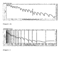
- the advantage of the technique of the present invention is evident from a comparison of Figures 2a and 2b.
- Fig. 2a displays the output power of a device at uniform current intervals in the direction that tuning efficiency variations are to be suppressed (linear power line).
- Fig. 2b displays the output power across the same range, but with the effects of tuning efficiency variation suppressed (i.e. a non-linear power line as provided by the technique of the present invention).
- a mode jump should be distinguishable by a discontinuity in power or frequency. It will be apparent from an inspection of the two Figures, that there is a large variation in the distance between mode jumps in the linear line relative to the non-linear line ( Figure 2b). Although both lines contain the same amount of power samples, it is clear that there are not enough samples in the linear line to easily extract important signal characteristics at low currents. However, the equivalent data in the non-linear power line is easily extractable.
- each point midway between two mode jumps (an instance of which is marked as the vertical line X-X in Fig. 2b) will also be the centre of its tuning range. This means that the point will be at the mean frequency for that mode, and will benefit from maximum side mode suppression. This makes it an ideal choice as the operating point for that mode.
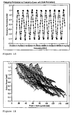
- the mode width (in current) at relative tuning currents in the laser describes the relationship between tuning rate and current(GHz/mA). It will be appreciated that the Mode Width is proportional to tuning rate vs. tuning current, which can be understood in terms of the Bragg current as meaning that the width of the mode in Bragg current is the relative size of the reflection peak that is causing the laser to operate at this frequency relative to the adjacent modes of lasing of the laser.
- Mode modulation is caused by extra Fabry Perot cavities existing in the laser and is normally due to an undesirable reflection at the interface between the individual sections of the laser. These reflections when added to the desired reflections from the Bragg etc.. cause a modulation in the mode width of the laser.
- Such a plot is shown in Figure 9 and can be obtained by some wavelength measurements such as a wavelength meter or equivalent or, as previously described by obtaining a plot of mode position vs Bragg current and sampling some frequencies either using a wavelength meter or using the setup as in Figure 2.
- the mode modulation is caused by a reflection between the gain section and the phase section of the laser and the period of modulation is approximately 125 GHz. This corresponds to a cavity length in the device of approx 340 ⁇ m which is as expected.
- This measurement is a very good detector of internal reflection in the tuneable laser and can be obtained from a simple power plane of a tuneable laser. This measurement is fast and can be used in the characterisation of tuneable lasers in a production environment. As the result obtained can be easily thresholded to detect when the internal reflections are too large the device will not meet the required specification it is ideal for Pass/ Fail criterion required in an automated production system.
- All tuneable devices suffer power loss due to increasing currents in the passive sections.
- An objective of device calibration is to not only obtain operating points at pre-defined frequencies within the device band, but to ensure those points are of a certain output power level. Based upon an assumed relationship between power loss and passive section currents, the input gain current may be increased in such a way as to counter the loss.
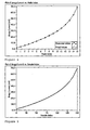
- this data may be used to plot a DBR current versus frequency index relationship (each unit increase in value represents a uniform jump in frequency).
- a 2 nd order polynomial function was then fitted to this data, bound by its upper and lower limits. Both the original data and the fitted polynomial function are shown in Fig. 4.
- This it will be appreciated is a standard quadratic polynomial which maps uniform steps in frequency to non-uniform steps in section current across the full range of the device.
- equations 1,2 and 3 can be implemented in a computer program or software for example C++ or visual basic in order to implement various aspects of the present invention, however it will be understood to the person skilled in the art that any computer program maybe used. It will be further appreciated that various aspects of the present invention could be implemented in a Field Programmable Gate Array (FPGA) or other logic hardware implementation.
- FPGA Field Programmable Gate Array
- Figs. 6 and 7 Shown in Figs. 6 and 7 is a comparison between a 300 x 300 linear power plane over the range of DBR currents described by the function of equation (3) and shown in Fig 5, and a non-linear plane over the same range of currents.
- the plane of Figure 6 is formed using conventional techniques such as those described in "Fast Accurate Characterisation of a GCSR laser over the complete EDFA Band" Tom Farrell et al. LEOS' 99 November, San Francisco, whereas that of Figure 7 is formed using the technique of the present invention.
- the relative uniformity of the width of each mode in the non-linear plane (Figure 7) is apparent especially when compared to the linear plane ( Figure 6).
- a DBR type laser device enables the power plane characterising the device to be effected on a single measurement set.
- several measurements may be required to fully characterise the device. For example using a SG-DBR device it is necessary to measure the output power vs. all of the coarse tuning currents, and for a 4-section SG-DBR laser this results in a plane. These measurements are repeated as a function of any other tuning sections that the device may have. For example with an SG-DBR laser several planes are measured of Front grating vs. Back grating against phase current.
- hysteresis can be represented in a similar method to that of mode modulation. This means that the hysteresis of the mode jumps as a percentage of the mode width can be plotted as a function of the wavelength of the laser, where the wavelength of the laser is the output wavelength exactly in between the mode jumps. This allows an improved quantitative method of representing this effect similar to that of mode modulation.
- the present invention provides for a method that compensates for tuning efficiency in a laser diode device, by providing a technique that enables a different sampling rate to be applied in different regions of interest in the power plane of the device.
- the present invention provides for the provision of a graph of the relative tuning rates of a section of a multi-section tunable laser by finding the relative positions of modes in the laser.
- the mode widths can be used to get mode modulation of a tunable laser.
- the present invention additionally provides for the measurement of a plane which takes all of the above into account and compensates for the resulting in a measurement plane where either the relative size of modes is constant or the power jumps due to mode jumps are equalised.
- the embodiments in the invention described with reference to the drawings comprise a computer apparatus and/or processes performed in a computer apparatus.
- the invention also extends to computer programs, particularly computer programs stored on or in a carrier adapted to bring the invention into practice.
- the program may be in the form of source code, object code, or a code intermediate source and object code, such as in partially compiled form or in any other form suitable for use in the implementation of the method according to the invention.
- the carrier may comprise a storage medium such as ROM, e.g. CD ROM, or magnetic recording medium, e.g. a floppy disk or hard disk.
- the carrier may be an electrical or optical signal which may be transmitted via an electrical or an optical cable or by radio or other means.
Landscapes
- Physics & Mathematics (AREA)
- Condensed Matter Physics & Semiconductors (AREA)
- General Physics & Mathematics (AREA)
- Electromagnetism (AREA)
- Optics & Photonics (AREA)
- Semiconductor Lasers (AREA)
Claims (36)
- Verfahren zum Normalisieren von Ausgangswerten einer Laserdiode mit folgenden Schritten:a) Verändern der Steuerströme an einer spezifischen Sektion eines Laserdioden-Bauelements über einen Wertebereich eines nicht-linearen Probenindex, um einen Satz von Ausgangswerten für die Sektion der Laserdiode zu erhalten, gekennzeichnet durch folgende Schritte:b) Normalisieren des Satzes von Ausgangswerten, um Nicht-Linearitäten in den Ausgangswerten dadurch zu kompensieren, dass eine Änderung in dem Verhältnis zwischen den Steuerströmen und dem nicht-linearen Probenindex erfolgt, wobei der nicht-lineare Probenindex durch eine nicht-lineare Transformation bewirkt wird, die auf einen linearen Strom-Probenindex angewendet wird, wodurch die Steuerströme und die Ausgangswerte verändert werden, so dass die Anwendung der nicht-linearen Transformation zu einer Entzerrung der Modenbreite führt, um so eine einheitliche Modenbreiten-Schrittgröße für die nachfolgende Kalibrierung des Lasers zu erhalten.
- Verfahren nach Anspruch 1, wobei die Ausgangswerte die Leistung oder Frequenz darstellen.
- Verfahren nach Anspruch 1 oder 2, gekennzeichnet durch den zusätzlichen Schritt eines Einholens eines Satzes von normalisierten Werten für eine oder mehrere weitere Sektionen des Lasers umfasst.
- Verfahren nach Anspruch 1, wobei die erzeugte Transformation im folgenden dazu verwendet wird, eine weitere Erzeugung eines Satzes von Ausgangswerten für mehrere Kombinationen von Steuerströmen oder Sektionen für das Laser-Bauelement zu bewirken, wobei der erzeugte Satz durch Anwendung der Transformation normalisiert wurde.
- Verfahren nach Anspruch 1, wobei die Normalisierung der Ausgangswerte unter Benutzung des Stromes der Modensprünge hervorgerufen wird.
- Verfahren nach Anspruch 5, wobei Modensprünge durch eine Leistungsmessung ermittelt werden.
- Verfahren nach Anspruch 6, wobei die Modensprünge durch Unstetigkeiten in einer Leistungsmessung dargestellt werden.
- Verfahren nach Anspruch 5, wobei Modensprünge durch eine Frequenzmessung ermittelt werden.
- Verfahren nach Anspruch 6, wobei die Modensprünge durch einen Schritt in einer Frequenzmessung dargestellt werden.
- Verfahren nach Anspruch 1, wobei das Verfahren zusätzlich den Schritt eines Bestimmens von Abweichungen in der Modenbreite umfasst, wodurch Hinweise auf die Intaktheit des Laser-Bauelements zur Verfügung gestellt werden.
- Verfahren nach Anspruch 1, wobei die Normalisierung unter Benutzung eines relativen Verlusts der Sektion als Funktion des Steuerstroms durchgeführt wird.
- Verfahren nach Anspruch 11, wobei der Verstärkungsstrom des Laser-Bauelements unter Benutzung der Normalisierung verändert werden kann.
- Verfahren nach Anspruch 1, wobei die Normalisierungs-Ausgangswerte eine Bestimmung der Modenlokalisierung ermöglichen.
- Verfahren nach Anspruch 13, wobei das Verfahren zusätzlich den Schritt eines Bestimmens geeigneter Arbeitspunkte umfasst, wobei die Arbeitspunkte auf der Basis einer Bestimmung eines Mittel-Punkts von Frequenzwerten für eine spezifische Mode wählbar sind.
- Verfahren nach Anspruch 14, wobei sich der Arbeitspunkt bei der mittleren Frequenz dieser Mode befindet und von einer maximalen Nebenmoden-Unterdrückung begünstigt wird.
- Verfahren nach Anspruch 13, wobei die Moden durch Ausführen eines Differenzierens der normalisierten Werte lokalisierbar sind.
- Ein Computerprogramm mit Programmanweisungen, die einen Computer dazu veranlassen, das Verfahren nach einem der Ansprüche 1 bis 16 auszuführen.
- Computerprogramm nach Anspruch 17 auf einem Aufzeichnungsmedium ausgeführt.
- Computerprogramm nach Anspruch 17 auf einem Trägersignal ausgeführt.
- Computerprogramm nach Anspruch 17 in einem Nur-LeseSpeicher (read only memory) ausgeführt.
- Steuersystem zum Normalisieren der Ausgangswerte einer Laserdiode, wobei das System folgendes aufweist:Mittel zum Verändern der Steuerströme einer spezifischen Sektion eines Laserdioden-Bauelements über einen Wertebereich eines nicht-linearen Probenindex, um einen Satz von Ausgangswerten für die Sektion der Laserdiode zu erhalten, dadurch gekennzeichnet, dass das System Mittel zum Normalisieren des Satzes von Ausgangswerten aufweist, um Nicht-Linearitäten in den Ausgangswerten dadurch zu kompensieren, dass eine Änderung in in dem Verhältnis zwischen den Steuerströmen und dem nicht-linearen Probenindex herbeigeführt wird, wobei der nicht-lineare Probenindex durch eine nicht-lineare Transformation bewirkt wird, die auf einen linearen Strom-Probenindex angewendet wird, wobei die Steuerströme und die Ausgangswerte derart geregelt werden, dass die Anwendung der nicht-linearen Transformation eine Entzerrung der Modenbreite hervorruft, um so eine einheitliche Modenbreiten-Schrittgröße für die nachfolgende Kalibrierung des Lasers zu erhalten.
- System nach Anspruch 21, wobei die Ausgangswerte die Leistung oder Frequenz darstellen.
- System nach Anspruch 21 oder 22, wobei das System zusätzlich Mittel zum Erhalten eines Satzes von normalisierten Werten für eine oder mehrere weitere Sektionen des Lasers umfasst.
- System nach Anspruch 21, wobei die erzeugte Transformation im folgenden zum Ausführen einer weiteren Erzeugung eines Satzes von Ausgangswerten für mehrere Kombinationen von Steuerströmen oder Sektionen für das Laser-Bauelement verwendet wird, wobei der erzeugte Satz durch Anwendung der Transformation normalisiert worden ist.
- System nach Anspruch 21, wobei die Normalisierung der Ausgangswerte unter Benutzung des Stromes der Modensprünge durchgeführt wird.
- System nach Anspruch 25, wobei Modensprünge durch eine Leistungsmessung ermittelt werden.
- System nach Anspruch 26, wobei Modensprünge als Unstetigkeiten durch eine Leistungsmessung dargestellt sind.
- System nach Anspruch 25, wobei Modensprünge durch eine Frequenzmessung ermittelt werden.
- System nach Anspruch 26, wobei Modensprünge als Schritt in einer Frequenzmessung dargestellt sind.
- System nach Anspruch 21, wobei das System zusätzlich Mittel zum Bestimmen von Abweichungen in der Modenbreite aufweist, wodurch Hinweise auf die Intaktheit des Laser-Bauelements zur Verfügung gestellt werden.
- System nach Anspruch 21, wobei die Normalisierung unter Benutzung eines relativen Verlusts der Sektion in Funktion des Steuerstroms durchgeführt wird.
- System nach Anspruch 31, wobei der Verstärkungsstrom des Laser-Bauelements unter Benutzung der Normalisierung veränderbar ist.
- System nach Anspruch 21, wobei die Normalisierungs-Ausgangswerte eine Bestimmung der Modenlokalisierung ermöglichen.
- System nach Anspruch 33, wobei das System zusätzlich Mittel zum Bestimmen geeigneter Arbeitspunkte umfasst, wobei die Arbeitspunkte auf der Basis einer Bestimmung eines Mittel-Punkts von Frequenzwerten für eine spezifische Mode wählbar sind.
- System nach Anspruch 34, wobei sich der Arbeitspunkt bei der mittleren Frequenz für diese Mode befindet und von einer maximalen Nebenmoden-Unterdrückung begünstigt wird.
- System nach Anspruch 33, wobei die Moden durch Ausführen eines Differenzierens der normalisierten Werte lokalisierbar sind.
Applications Claiming Priority (3)
| Application Number | Priority Date | Filing Date | Title |
|---|---|---|---|
| IE20020709A IES20020709A2 (en) | 2002-09-02 | 2002-09-02 | Method for optimising non-linear laser control effects |
| IE20020709 | 2002-09-02 | ||
| PCT/IE2003/000116 WO2004021534A1 (en) | 2002-09-02 | 2003-08-29 | Compensation of mode jumps in multi section lasers |
Publications (2)
| Publication Number | Publication Date |
|---|---|
| EP1535375A1 EP1535375A1 (de) | 2005-06-01 |
| EP1535375B1 true EP1535375B1 (de) | 2007-04-11 |
Family
ID=31972030
Family Applications (1)
| Application Number | Title | Priority Date | Filing Date |
|---|---|---|---|
| EP03791152A Expired - Lifetime EP1535375B1 (de) | 2002-09-02 | 2003-08-29 | Kompensation von modensprüngen in durchstimmbaren lasern mit mehreren sektionen |
Country Status (7)
| Country | Link |
|---|---|
| US (1) | US20060109879A1 (de) |
| EP (1) | EP1535375B1 (de) |
| AT (1) | ATE359612T1 (de) |
| AU (1) | AU2003264834A1 (de) |
| DE (1) | DE60313183T2 (de) |
| IE (1) | IES20020709A2 (de) |
| WO (1) | WO2004021534A1 (de) |
Families Citing this family (3)
| Publication number | Priority date | Publication date | Assignee | Title |
|---|---|---|---|---|
| US8964806B2 (en) * | 2012-01-19 | 2015-02-24 | Insight Photonic Solutions, Inc. | System and method for generating an optimum side-mode suppression ratio continuous tuning path for a semiconductor tunable laser |
| CN106299990B (zh) * | 2016-08-31 | 2019-03-08 | 武汉光迅科技股份有限公司 | 一种用于光纤放大器非线性激光器控制方法及装置 |
| WO2024010847A1 (en) * | 2022-07-06 | 2024-01-11 | Analog Photonics LLC | Managing laser system optical characteristics |
Family Cites Families (10)
| Publication number | Priority date | Publication date | Assignee | Title |
|---|---|---|---|---|
| US6529531B1 (en) * | 1997-07-22 | 2003-03-04 | Cymer, Inc. | Fast wavelength correction technique for a laser |
| SE519081C3 (sv) * | 1998-01-21 | 2003-02-19 | Altitun Ab | Förfarande och anordning för optimering av lasrars operationspunkt, jämte anordning |
| AU2001251214A1 (en) * | 2000-03-30 | 2001-10-15 | National Institute Of Standards And Technology ("Nist") | Mode-locked pulsed laser system and method |
| EP1172905A1 (de) * | 2000-07-11 | 2002-01-16 | Interuniversitair Microelektronica Centrum Vzw | Verfahren und Vorrichtung zur Kontrolle einer Laserstruktur |
| CN1302587C (zh) * | 2001-06-22 | 2007-02-28 | 松下电器产业株式会社 | 光源装置 |
| WO2003038954A2 (en) * | 2001-10-30 | 2003-05-08 | Tsunami Photonics Limited | Stability factors for tuneable multi-section semiconductor lasers |
| US20040174915A1 (en) * | 2002-09-18 | 2004-09-09 | Adc Telecommunications, Inc. | Method for characterizing tunable lasers |
| US7151789B2 (en) * | 2002-12-20 | 2006-12-19 | Spectalis Corp | External-cavity lasers |
| US7116695B2 (en) * | 2004-09-28 | 2006-10-03 | Cymer, Inc. | Laser output light pulse beam parameter transient correction system |
| JP4950519B2 (ja) * | 2005-06-30 | 2012-06-13 | キヤノン株式会社 | 光波長変換装置、光波長変換方法、及びそれを用いた画像形成装置 |
-
2002
- 2002-09-02 IE IE20020709A patent/IES20020709A2/en not_active IP Right Cessation
-
2003
- 2003-08-29 EP EP03791152A patent/EP1535375B1/de not_active Expired - Lifetime
- 2003-08-29 AT AT03791152T patent/ATE359612T1/de not_active IP Right Cessation
- 2003-08-29 DE DE60313183T patent/DE60313183T2/de not_active Expired - Lifetime
- 2003-08-29 AU AU2003264834A patent/AU2003264834A1/en not_active Abandoned
- 2003-08-29 US US10/526,289 patent/US20060109879A1/en not_active Abandoned
- 2003-08-29 WO PCT/IE2003/000116 patent/WO2004021534A1/en not_active Ceased
Also Published As
| Publication number | Publication date |
|---|---|
| DE60313183D1 (de) | 2007-05-24 |
| AU2003264834A1 (en) | 2004-03-19 |
| EP1535375A1 (de) | 2005-06-01 |
| US20060109879A1 (en) | 2006-05-25 |
| IES20020709A2 (en) | 2004-03-10 |
| DE60313183T2 (de) | 2007-12-20 |
| WO2004021534A1 (en) | 2004-03-11 |
| ATE359612T1 (de) | 2007-05-15 |
Similar Documents
| Publication | Publication Date | Title |
|---|---|---|
| US9595804B2 (en) | System and method of dynamic and adaptive creation of a wavelength continuous and prescribed wavelength versus time sweep from a laser | |
| US6504856B1 (en) | Method and apparatus for optimizing operation points of a tunable laser | |
| US10355446B1 (en) | System and method for traversing multivariate paths using multi-dimensional control of an electromagnetic radiation source | |
| US7649917B2 (en) | Method and system for continuous sweeping of a tunable laser | |
| US20060239306A1 (en) | Characterization and non-invasive correction of operational control currents of a tuneable laser | |
| US7436864B2 (en) | Method for optimising the calibration process of a tuneable laser | |
| US20060109879A1 (en) | Compensation of mode jumps in multi section lasers | |
| US7478007B2 (en) | Method for compensation of degradation in tunable lasers | |
| IE20020709U1 (en) | Method for optimising non-linear laser control effects | |
| EP1442509B1 (de) | Stabilitätsfaktoren für durchstimmbare halbleiterlaser mit mehreren sektionen | |
| IES83422Y1 (en) | Method for optimising non-linear laser control effects | |
| US7680167B2 (en) | Method and system for detection of regions of instability in multi-section tunable lasers | |
| Cui et al. | A Fast Look-up Table Generation Method for Modulated Grating Y-Branch Lase | |
| GB2412230A (en) | Laser calibration, monitoring and control | |
| Cheng et al. | Edge-filtering-based high-frequency parameter characterization for MG-Y lasers | |
| Yu et al. | Fast intra-modal and inter-modal wavelength switching of a high-speed SG-DBR laser for dynamic wavelength routing | |
| Heininger | Longitudinal cavity mode referenced spline tuning for widely tunable MG-Y branch semiconductor laser | |
| US20050276288A1 (en) | Device and method for inspecting wavelength-variable semiconductor laser, and method for inspecting coherent source | |
| GB2633329A (en) | Wavelength stabilisation method and apparatus | |
| Ke et al. | Frequency drift and instantaneous linewidth broadening of phase-section tuned SG-DBR laser | |
| Morthier et al. | Introductory physics | |
| IE20020187U1 (en) | Method for optimising the calibration process of a tuneable laser | |
| IES83706Y1 (en) | Method and apparatus for continuous sweeping of a tunable laser | |
| IE20030281U1 (en) | Method and apparatus for continuous sweeping of a tunable laser |
Legal Events
| Date | Code | Title | Description |
|---|---|---|---|
| PUAI | Public reference made under article 153(3) epc to a published international application that has entered the european phase |
Free format text: ORIGINAL CODE: 0009012 |
|
| 17P | Request for examination filed |
Effective date: 20050316 |
|
| AK | Designated contracting states |
Kind code of ref document: A1 Designated state(s): AT BE BG CH CY CZ DE DK EE ES FI FR GB GR HU IE IT LI LU MC NL PT RO SE SI SK TR |
|
| AX | Request for extension of the european patent |
Extension state: AL LT LV MK |
|
| DAX | Request for extension of the european patent (deleted) | ||
| RTI1 | Title (correction) |
Free format text: COMPENSATION OF MODE JUMPS IN TUNABLE MULTI SECTION LASERS |
|
| GRAP | Despatch of communication of intention to grant a patent |
Free format text: ORIGINAL CODE: EPIDOSNIGR1 |
|
| RIN1 | Information on inventor provided before grant (corrected) |
Inventor name: RYAN, NEIL Inventor name: LEVINS, JOHN Inventor name: FARRELL, TOM |
|
| GRAS | Grant fee paid |
Free format text: ORIGINAL CODE: EPIDOSNIGR3 |
|
| GRAA | (expected) grant |
Free format text: ORIGINAL CODE: 0009210 |
|
| AK | Designated contracting states |
Kind code of ref document: B1 Designated state(s): AT BE BG CH CY CZ DE DK EE ES FI FR GB GR HU IE IT LI LU MC NL PT RO SE SI SK TR |
|
| PG25 | Lapsed in a contracting state [announced via postgrant information from national office to epo] |
Ref country code: SI Free format text: LAPSE BECAUSE OF FAILURE TO SUBMIT A TRANSLATION OF THE DESCRIPTION OR TO PAY THE FEE WITHIN THE PRESCRIBED TIME-LIMIT Effective date: 20070411 Ref country code: CH Free format text: LAPSE BECAUSE OF FAILURE TO SUBMIT A TRANSLATION OF THE DESCRIPTION OR TO PAY THE FEE WITHIN THE PRESCRIBED TIME-LIMIT Effective date: 20070411 Ref country code: LI Free format text: LAPSE BECAUSE OF FAILURE TO SUBMIT A TRANSLATION OF THE DESCRIPTION OR TO PAY THE FEE WITHIN THE PRESCRIBED TIME-LIMIT Effective date: 20070411 Ref country code: FI Free format text: LAPSE BECAUSE OF FAILURE TO SUBMIT A TRANSLATION OF THE DESCRIPTION OR TO PAY THE FEE WITHIN THE PRESCRIBED TIME-LIMIT Effective date: 20070411 |
|
| REG | Reference to a national code |
Ref country code: GB Ref legal event code: FG4D |
|
| REG | Reference to a national code |
Ref country code: CH Ref legal event code: EP |
|
| REG | Reference to a national code |
Ref country code: IE Ref legal event code: FG4D |
|
| REF | Corresponds to: |
Ref document number: 60313183 Country of ref document: DE Date of ref document: 20070524 Kind code of ref document: P |
|
| PG25 | Lapsed in a contracting state [announced via postgrant information from national office to epo] |
Ref country code: SE Free format text: LAPSE BECAUSE OF FAILURE TO SUBMIT A TRANSLATION OF THE DESCRIPTION OR TO PAY THE FEE WITHIN THE PRESCRIBED TIME-LIMIT Effective date: 20070711 |
|
| PG25 | Lapsed in a contracting state [announced via postgrant information from national office to epo] |
Ref country code: ES Free format text: LAPSE BECAUSE OF FAILURE TO SUBMIT A TRANSLATION OF THE DESCRIPTION OR TO PAY THE FEE WITHIN THE PRESCRIBED TIME-LIMIT Effective date: 20070722 |
|
| PG25 | Lapsed in a contracting state [announced via postgrant information from national office to epo] |
Ref country code: PT Free format text: LAPSE BECAUSE OF FAILURE TO SUBMIT A TRANSLATION OF THE DESCRIPTION OR TO PAY THE FEE WITHIN THE PRESCRIBED TIME-LIMIT Effective date: 20070911 |
|
| NLV1 | Nl: lapsed or annulled due to failure to fulfill the requirements of art. 29p and 29m of the patents act | ||
| ET | Fr: translation filed | ||
| REG | Reference to a national code |
Ref country code: CH Ref legal event code: PL |
|
| PG25 | Lapsed in a contracting state [announced via postgrant information from national office to epo] |
Ref country code: AT Free format text: LAPSE BECAUSE OF FAILURE TO SUBMIT A TRANSLATION OF THE DESCRIPTION OR TO PAY THE FEE WITHIN THE PRESCRIBED TIME-LIMIT Effective date: 20070411 |
|
| PG25 | Lapsed in a contracting state [announced via postgrant information from national office to epo] |
Ref country code: BE Free format text: LAPSE BECAUSE OF FAILURE TO SUBMIT A TRANSLATION OF THE DESCRIPTION OR TO PAY THE FEE WITHIN THE PRESCRIBED TIME-LIMIT Effective date: 20070411 |
|
| PG25 | Lapsed in a contracting state [announced via postgrant information from national office to epo] |
Ref country code: CZ Free format text: LAPSE BECAUSE OF FAILURE TO SUBMIT A TRANSLATION OF THE DESCRIPTION OR TO PAY THE FEE WITHIN THE PRESCRIBED TIME-LIMIT Effective date: 20070411 Ref country code: NL Free format text: LAPSE BECAUSE OF FAILURE TO SUBMIT A TRANSLATION OF THE DESCRIPTION OR TO PAY THE FEE WITHIN THE PRESCRIBED TIME-LIMIT Effective date: 20070411 Ref country code: BG Free format text: LAPSE BECAUSE OF FAILURE TO SUBMIT A TRANSLATION OF THE DESCRIPTION OR TO PAY THE FEE WITHIN THE PRESCRIBED TIME-LIMIT Effective date: 20070711 Ref country code: DK Free format text: LAPSE BECAUSE OF FAILURE TO SUBMIT A TRANSLATION OF THE DESCRIPTION OR TO PAY THE FEE WITHIN THE PRESCRIBED TIME-LIMIT Effective date: 20070411 |
|
| PLBE | No opposition filed within time limit |
Free format text: ORIGINAL CODE: 0009261 |
|
| STAA | Information on the status of an ep patent application or granted ep patent |
Free format text: STATUS: NO OPPOSITION FILED WITHIN TIME LIMIT |
|
| PG25 | Lapsed in a contracting state [announced via postgrant information from national office to epo] |
Ref country code: SK Free format text: LAPSE BECAUSE OF FAILURE TO SUBMIT A TRANSLATION OF THE DESCRIPTION OR TO PAY THE FEE WITHIN THE PRESCRIBED TIME-LIMIT Effective date: 20070411 |
|
| 26N | No opposition filed |
Effective date: 20080114 |
|
| PG25 | Lapsed in a contracting state [announced via postgrant information from national office to epo] |
Ref country code: MC Free format text: LAPSE BECAUSE OF NON-PAYMENT OF DUE FEES Effective date: 20070831 Ref country code: IT Free format text: LAPSE BECAUSE OF FAILURE TO SUBMIT A TRANSLATION OF THE DESCRIPTION OR TO PAY THE FEE WITHIN THE PRESCRIBED TIME-LIMIT Effective date: 20070411 Ref country code: GR Free format text: LAPSE BECAUSE OF FAILURE TO SUBMIT A TRANSLATION OF THE DESCRIPTION OR TO PAY THE FEE WITHIN THE PRESCRIBED TIME-LIMIT Effective date: 20070712 |
|
| PG25 | Lapsed in a contracting state [announced via postgrant information from national office to epo] |
Ref country code: RO Free format text: LAPSE BECAUSE OF FAILURE TO SUBMIT A TRANSLATION OF THE DESCRIPTION OR TO PAY THE FEE WITHIN THE PRESCRIBED TIME-LIMIT Effective date: 20070411 |
|
| PG25 | Lapsed in a contracting state [announced via postgrant information from national office to epo] |
Ref country code: IE Free format text: LAPSE BECAUSE OF NON-PAYMENT OF DUE FEES Effective date: 20070829 |
|
| PG25 | Lapsed in a contracting state [announced via postgrant information from national office to epo] |
Ref country code: EE Free format text: LAPSE BECAUSE OF FAILURE TO SUBMIT A TRANSLATION OF THE DESCRIPTION OR TO PAY THE FEE WITHIN THE PRESCRIBED TIME-LIMIT Effective date: 20070411 |
|
| PG25 | Lapsed in a contracting state [announced via postgrant information from national office to epo] |
Ref country code: CY Free format text: LAPSE BECAUSE OF FAILURE TO SUBMIT A TRANSLATION OF THE DESCRIPTION OR TO PAY THE FEE WITHIN THE PRESCRIBED TIME-LIMIT Effective date: 20070411 |
|
| PG25 | Lapsed in a contracting state [announced via postgrant information from national office to epo] |
Ref country code: LU Free format text: LAPSE BECAUSE OF NON-PAYMENT OF DUE FEES Effective date: 20070829 |
|
| PG25 | Lapsed in a contracting state [announced via postgrant information from national office to epo] |
Ref country code: TR Free format text: LAPSE BECAUSE OF FAILURE TO SUBMIT A TRANSLATION OF THE DESCRIPTION OR TO PAY THE FEE WITHIN THE PRESCRIBED TIME-LIMIT Effective date: 20070411 Ref country code: HU Free format text: LAPSE BECAUSE OF FAILURE TO SUBMIT A TRANSLATION OF THE DESCRIPTION OR TO PAY THE FEE WITHIN THE PRESCRIBED TIME-LIMIT Effective date: 20071012 |
|
| REG | Reference to a national code |
Ref country code: FR Ref legal event code: PLFP Year of fee payment: 13 |
|
| REG | Reference to a national code |
Ref country code: FR Ref legal event code: PLFP Year of fee payment: 14 |
|
| REG | Reference to a national code |
Ref country code: FR Ref legal event code: PLFP Year of fee payment: 15 |
|
| REG | Reference to a national code |
Ref country code: FR Ref legal event code: PLFP Year of fee payment: 16 |
|
| PGFP | Annual fee paid to national office [announced via postgrant information from national office to epo] |
Ref country code: DE Payment date: 20190830 Year of fee payment: 17 Ref country code: FR Payment date: 20190827 Year of fee payment: 17 |
|
| PGFP | Annual fee paid to national office [announced via postgrant information from national office to epo] |
Ref country code: GB Payment date: 20190816 Year of fee payment: 17 |
|
| REG | Reference to a national code |
Ref country code: DE Ref legal event code: R119 Ref document number: 60313183 Country of ref document: DE |
|
| GBPC | Gb: european patent ceased through non-payment of renewal fee |
Effective date: 20200829 |
|
| PG25 | Lapsed in a contracting state [announced via postgrant information from national office to epo] |
Ref country code: FR Free format text: LAPSE BECAUSE OF NON-PAYMENT OF DUE FEES Effective date: 20200831 Ref country code: DE Free format text: LAPSE BECAUSE OF NON-PAYMENT OF DUE FEES Effective date: 20210302 |
|
| PG25 | Lapsed in a contracting state [announced via postgrant information from national office to epo] |
Ref country code: GB Free format text: LAPSE BECAUSE OF NON-PAYMENT OF DUE FEES Effective date: 20200829 |