EP1535295B1 - Vakuumlichtbogenlöscheinrichtung mit kugelanordnung angetrieben von einer gaserzeugungsvorrichtung - Google Patents
Vakuumlichtbogenlöscheinrichtung mit kugelanordnung angetrieben von einer gaserzeugungsvorrichtung Download PDFInfo
- Publication number
- EP1535295B1 EP1535295B1 EP03732798A EP03732798A EP1535295B1 EP 1535295 B1 EP1535295 B1 EP 1535295B1 EP 03732798 A EP03732798 A EP 03732798A EP 03732798 A EP03732798 A EP 03732798A EP 1535295 B1 EP1535295 B1 EP 1535295B1
- Authority
- EP
- European Patent Office
- Prior art keywords
- vacuum arc
- lance
- arc interrupter
- assembly
- conductor
- Prior art date
- Legal status (The legal status is an assumption and is not a legal conclusion. Google has not performed a legal analysis and makes no representation as to the accuracy of the status listed.)
- Expired - Lifetime
Links
- 239000004020 conductor Substances 0.000 claims description 75
- 230000007704 transition Effects 0.000 claims description 24
- 238000004891 communication Methods 0.000 claims description 21
- 239000012530 fluid Substances 0.000 claims description 12
- PXHVJJICTQNCMI-UHFFFAOYSA-N Nickel Chemical compound [Ni] PXHVJJICTQNCMI-UHFFFAOYSA-N 0.000 description 4
- 239000006096 absorbing agent Substances 0.000 description 3
- 239000000956 alloy Substances 0.000 description 3
- 239000000463 material Substances 0.000 description 3
- 230000035939 shock Effects 0.000 description 3
- 238000011144 upstream manufacturing Methods 0.000 description 3
- RYGMFSIKBFXOCR-UHFFFAOYSA-N Copper Chemical compound [Cu] RYGMFSIKBFXOCR-UHFFFAOYSA-N 0.000 description 2
- 229910000570 Cupronickel Inorganic materials 0.000 description 2
- 229910045601 alloy Inorganic materials 0.000 description 2
- 239000000919 ceramic Substances 0.000 description 2
- 229910052802 copper Inorganic materials 0.000 description 2
- 239000010949 copper Substances 0.000 description 2
- 230000008878 coupling Effects 0.000 description 2
- 238000010168 coupling process Methods 0.000 description 2
- 238000005859 coupling reaction Methods 0.000 description 2
- 230000005684 electric field Effects 0.000 description 2
- 238000012423 maintenance Methods 0.000 description 2
- 239000002184 metal Substances 0.000 description 2
- 229910052751 metal Inorganic materials 0.000 description 2
- 229910052759 nickel Inorganic materials 0.000 description 2
- 241000237858 Gastropoda Species 0.000 description 1
- 208000027418 Wounds and injury Diseases 0.000 description 1
- 230000015556 catabolic process Effects 0.000 description 1
- 238000010276 construction Methods 0.000 description 1
- 230000006378 damage Effects 0.000 description 1
- 238000001514 detection method Methods 0.000 description 1
- 230000005611 electricity Effects 0.000 description 1
- 230000005672 electromagnetic field Effects 0.000 description 1
- 238000013467 fragmentation Methods 0.000 description 1
- 238000006062 fragmentation reaction Methods 0.000 description 1
- 230000005484 gravity Effects 0.000 description 1
- 239000012535 impurity Substances 0.000 description 1
- 208000014674 injury Diseases 0.000 description 1
- 238000009413 insulation Methods 0.000 description 1
- 230000008018 melting Effects 0.000 description 1
- 238000002844 melting Methods 0.000 description 1
- 239000012811 non-conductive material Substances 0.000 description 1
- 239000007787 solid Substances 0.000 description 1
Images


Classifications
-
- H—ELECTRICITY
- H01—ELECTRIC ELEMENTS
- H01H—ELECTRIC SWITCHES; RELAYS; SELECTORS; EMERGENCY PROTECTIVE DEVICES
- H01H33/00—High-tension or heavy-current switches with arc-extinguishing or arc-preventing means
- H01H33/60—Switches wherein the means for extinguishing or preventing the arc do not include separate means for obtaining or increasing flow of arc-extinguishing fluid
- H01H33/66—Vacuum switches
- H01H33/666—Operating arrangements
-
- H—ELECTRICITY
- H01—ELECTRIC ELEMENTS
- H01H—ELECTRIC SWITCHES; RELAYS; SELECTORS; EMERGENCY PROTECTIVE DEVICES
- H01H33/00—High-tension or heavy-current switches with arc-extinguishing or arc-preventing means
- H01H33/02—Details
- H01H33/28—Power arrangements internal to the switch for operating the driving mechanism
- H01H33/30—Power arrangements internal to the switch for operating the driving mechanism using fluid actuator
- H01H33/32—Power arrangements internal to the switch for operating the driving mechanism using fluid actuator pneumatic
-
- H—ELECTRICITY
- H01—ELECTRIC ELEMENTS
- H01H—ELECTRIC SWITCHES; RELAYS; SELECTORS; EMERGENCY PROTECTIVE DEVICES
- H01H33/00—High-tension or heavy-current switches with arc-extinguishing or arc-preventing means
- H01H33/60—Switches wherein the means for extinguishing or preventing the arc do not include separate means for obtaining or increasing flow of arc-extinguishing fluid
- H01H33/66—Vacuum switches
- H01H33/664—Contacts; Arc-extinguishing means, e.g. arcing rings
- H01H33/6646—Contacts; Arc-extinguishing means, e.g. arcing rings having non flat disc-like contact surface
-
- H—ELECTRICITY
- H01—ELECTRIC ELEMENTS
- H01H—ELECTRIC SWITCHES; RELAYS; SELECTORS; EMERGENCY PROTECTIVE DEVICES
- H01H39/00—Switching devices actuated by an explosion produced within the device and initiated by an electric current
- H01H39/004—Closing switches
-
- H—ELECTRICITY
- H01—ELECTRIC ELEMENTS
- H01H—ELECTRIC SWITCHES; RELAYS; SELECTORS; EMERGENCY PROTECTIVE DEVICES
- H01H79/00—Protective switches in which excess current causes the closing of contacts, e.g. for short-circuiting the apparatus to be protected
Definitions
- This invention relates to a vacuum arc interrupter and, more specifically, to a vacuum arc interrupter that utilizes a bullet assembly that is actuated by a gas generating source.
- a vacuum arc interrupter utilizes two contacts in a vacuum chamber. One contact is fixed and the other contact is movable.
- the movable contact includes a stem, which is coupled to a bellows, that extends outside of the vacuum chamber.
- the spring is coupled to the stem and to a release device.
- the release device is coupled to an arc sensor in the LV or MV enclosure. The stem, and therefore the movable contact, moves from a first position at one end of the chamber to a second position at the opposite end of the chamber.
- One contact is coupled to the LV or MV circuit and the other contact is grounded.
- the first position of the piston corresponds to the open position of the contacts.
- the arc sensor actuates the spring release device, thereby allowing the contacts to move into the second position and short the circuit.
- Another device that is, a device which is not a vacuum arc interrupter, for shorting a circuit included a tapered slug which is propelled by high pressure gas into a tapered set of openings extending through two bus bars and a layer of insulation.
- the slug is maintained in a pressure chamber coupled to a gas-generating device. When gas is rapidly introduced to the pressure chamber, the slug is propelled into the tapered opening, contacting both bus bars.
- one bus is coupled to a live circuit and the other bus is grounded. Thus, when the slug contacts both buses, the circuit is shorted.
- Prior art vacuum arc interrupters require multiple components to be maintained in the vacuum chamber. Certain components, such as the bellows, are difficult and expensive to construct. Construction of the vacuum arc interrupter could be simplified if more components could be maintained outside of the vacuum chamber.
- Prior art vacuum arc interrupters utilizing springs because of their nature, do not have a means for stopping the upward motion of the movable contact. That is, the spring mechanism is structured to absorb the reactive forces caused by the contacts colliding.
- Certain prior art vacuum arc eliminators also include a combination of springs and shock absorbers. The use of a spring or a combination of a spring and a shock absorber reduces, but does not eliminate, the bounce which occurs when the moving component contacts the stationary component. Thus, the prior art vacuum arc interrupters do not have a mechanism for stopping the advance of the moving component.
- the slug relied on the application of gas pressure on the piston to ensure that the piston remained in the second position. Or, if the slug moved in a downward direction and the slug was heavy, gravity provided a sufficient force to hold the slug in place. That is, this system did not include a mechanical lock to maintain the slug in the second position.
- the prior art slugs have a generally flat pressure surface. Because the gas is typically introduced through a small opening, the pressure distribution on the slug pressure surface is uneven. The uneven pressure distribution prevents the slug from moving as fast as a slug where the pressure distribution is even. Another disadvantage of this device is that, where the slug is received in a conductor having a small cross-sectional area, the electromagnetic field created by the contact may be very strong.
- a vacuum arc interrupter that utilizes a bullet assembly to electrically link two conductors where a first conductor is maintained within a vacuum chamber and the second conductor is disposed outside of the vacuum chamber.
- a vacuum arc interrupter having a vacuum chamber assembly and an adjacent pressure chamber assembly.
- a first conductor is within a vacuum chamber in the vacuum chamber assembly, and a second conductor, which is part of the pressure chamber assembly, is disposed outside of the vacuum chamber.
- the two conductors are electrically coupled by a bullet assembly.
- the bullet assembly includes a conductive lance.
- the bullet assembly is slidably disposed within a pressure chamber in the pressure chamber assembly.
- the bullet assembly is originally in a first position where the entire bullet assembly is disposed within the pressure chamber.
- the bullet assembly moves to a second position where the lance contacts the second conductor and extends beyond the pressure chamber assembly to contact the first conductor.
- the lance punctures a seal that is integral to the vacuum chamber assembly.
- the pressure chamber includes a first sized portion and a second sized portion. Both the first sized portion and the second sized portion have a generally constant cross-sectional area, with the first sized portion having a smaller cross-sectional area than the second sized portion. Between the first sized portion and the second sized portion is a transition portion. The transition portion has a cross-sectional area that tapers from the cross-sectional area of the first sized portion to the cross-sectional area of the second sized portion.
- the first sized portion is in fluid communication with an inlet port opening. The inlet port opening is coupled to, and in fluid communication with, the gas generating device.
- the second sized portion is in fluid communication with a bullet assembly opening.
- the bullet assembly includes a piston assembly and the lance.
- the bullet assembly piston assembly has a first side and a second side.
- the first side will be the side exposed to the gas generating source and therefore may also be referred to as the pressure surface.
- the piston assembly pressure surface is not flat.
- gas from the gas generating source is dispersed across the surface of the pressure surface thereby reducing areas of localized pressure.
- the pressure surface may be either concave or convex.
- the pressure surface is convex, and, where the piston is circular, conical.
- the conical surface preferably, has a more obtuse angle than the angle of the taper of the pressure chamber transition portion. As such, there is a gap between the pressure surface and the sidewall of the transition portion.
- the gas entering the chamber first sized portion and the chamber transition portion contacts the conical surface and is dispersed in the gap.
- the dispersal of the gas creates an even pressure distribution on the pressure surface and causes the piston to move from a first position adjacent to the transition portion to a second position away from the transition portion.
- the bullet assembly lance is made from a conductive material and includes an elongated body having a tapered tip and a flared base.
- the tapered tip is structured to engage a cup on a first conductor, where the cup has a cavity corresponding to the shape of the lance tip. Alternatively, the cup may have a cavity that partially corresponds to the shape of the lance tip, thereby having an interference fit.
- the flared base is structured to correspond to the shape of a tapered passage in a conductor.
- the lance is sized so that as the flared base engages the tapered opening in one conductor, the tip firmly engages the cup disposed on the other conductor. Thus, the lance acts to electrically couple the two conductors.
- the vacuum arc interrupter has one conductor, typically the first conductor, coupled to, and in electrical communication with, a circuit.
- the second conductor is coupled to, and in electrical communication with, a ground.
- the circuit includes a low voltage or medium voltage device at a point downstream of the vacuum arc interrupter.
- the low voltage or medium voltage device includes an arc detector which is coupled to and structured to activate the gas generating device.
- the gas generating device When an arc is detected in the low voltage or medium voltage device, the gas generating device generates a gas which flows into the pressure chamber first sized portion and the transition portion gap.
- the gas generating device delivers gas at a pressure about 180 psi, through the inlet port into the chamber first size portion.
- This increase of pressure occurs in about 0.5 msec and causes the bullet assembly to move from the first position to the second position in less than 2.0 msec. Because the inlet port opening is on the piston first side, gas from the gas generating device will flow into the chamber first sized portion and transition portion and contact the angled piston first side. The angle of the piston first side assists the gas in dispersing through the chamber transition portion and thus creates an even pressure distribution on the piston first side.
- the lance passes through a tapered passage in the second conductor causing the lance to puncture the seal on the vacuum chamber.
- the flared base is sized to correspond to the tapered opening. Thus, when the flared base contact the tapered passage, the motion of the bullet assembly is stopped. At this the same time the flared base contacts the tapered passage, the lance tip contacts the first conductor, thereby electrically coupling the two conductors.
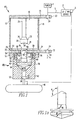
- a vacuum arc interrupter 10 includes a vacuum chamber assembly 12 and a pressure chamber assembly 14.
- the vacuum chamber assembly 12 includes a first conductor 16, a non-conductive housing 18, and a seal cup 20.
- the first conductor 16 is made from a conductive material and, preferably, is shaped as a circular disk.
- the first conductor 16 may include a radial extension 22 having an attachment opening 24 therethrough.
- the attachment opening 24 is structured to allow a power line to be coupled to the first conductor 16.
- the first conductor 16 also includes an electrode 23 having a stem 25 and a receiving cup 26.
- the cup 26 is disposed at the distal end of the stem 25 and extends into the vacuum chamber 36 described hereinafter.
- the cup 26 is made from a conductive material and includes a continuous sidewall 28 having an open end 29, thereby defining a cavity 30.
- the cup 26 is supported by the stem 25 so that the cup 26 is spaced from the first conductor 16.
- the open end 29 has a cross-sectional area that is smaller than the widest portion of the lance tip 118, described hereinafter.
- the cup 26 may have a cross-sectional area greater than is mechanically required.
- the stem 25 may have the same cross-sectional area, or be smaller than, the cup 26.
- the non-conductive housing 18 is made from a non-conductive material, preferably a ceramic.
- the non-conductive housing 18 has a shape that corresponds to the shape of the first conductor 16.
- the non-conductive housing 18 is a hollow cylinder.
- One axial end of the non-conductive housing 18 is sealingly coupled to the first conductor 16.
- the seal cup 20 includes a generally planar base member 32 and a sidewall 34 generally perpendicular thereto.
- the seal cup 20 is made from a rigid, non-brittle material such as a cupro-nickel alloy.
- the alloy material preferably has between about 50 to 95% copper, and more preferably about 70% copper, and between about 5 to 50% nickel, and more preferably about 30% nickel. The alloy may also have lesser amounts of other elements or impurities. Generally, the seal cup 20 material may be tom without a substantial amount of fragmentation.
- the seal cup sidewall 34 is sealingly coupled to the axial end of the non-conductive housing 18 opposite the first conductor 16. Thus, the combination of the first conductor 16, the non-conductive housing 18, and the seal cup 20 define a vacuum chamber 36.
- the seal cup 20 contacts the second conductor 70.
- the first conductor 16, or the electrode 23 if present, and the seal cup 20 are separated by a distance sufficient to lower the magnitude of the electric field to below that which would lead to an electrical breakdown within the vacuum.
- This distance is, generally, about 0.4 inch to 2.0 inches and varies depending upon the voltage in the system. For example, for a voltage of about 125 kilovolts, the distance is preferably about 0.6 inch.
- a ring shaped metal shield 35 may extend into the vacuum chamber 36 from the seal cup 20.
- the shield 35 extends adjacent to the seal cup side wall 34 and has a height sufficient so that the shield 35 is disposed between the point where the seal cup 20 is attached to the non-conductive housing 18 and the electrode 23.
- the upper seal cup 21 includes an opening to allow the stem 25 to pass therethrough.
- the pressure chamber assembly 14 includes a gas generation device 40, a pressure chamber body 42, a second conductor 70, and a bullet assembly 46.
- the gas generation device 40 may be any gas generation device such as those manufactured by TRW Airbag Systems GmbH & Co. KG, Wernher-Von-Braun-STR. 1, D-84544 Asehan am Inn, Germany.
- the pressure chamber body 42 is preferably cylindrical and includes a barrel 50 and a mounting flange 51.
- the barrel 50 has a first end 52 and a second end 54.
- the barrel 50 has an inlet port opening 56 on the first end 52 and a bullet assembly opening 58 at the second end 54.
- the inlet port opening 56 is smaller than the bullet assembly opening 58.
- the inlet port opening 56 is in fluid communication with the bullet assembly opening 58.
- the barrel 50 defines a pressure chamber 60.
- the pressure chamber 60 includes a first sized portion 62, a transition portion 64, and a second sized portion 66.
- the first sized portion 62 has a smaller cross-sectional area than the second sized portion 66.
- the first sized portion 62 is in fluid communication with the inlet port opening 56.
- the second sized portion 66 is in fluid communication with the bullet assembly opening 58.
- the transition portion 64 is disposed between, and in fluid communication with, the first sized portion 62 and the second sized portion 66.
- the transition portion 64 has a cross-sectional area that tapers from the cross-sectional area of the first sized portion 62 to the cross-sectional area of the second sized portion 66.
- the pressure chamber 60 preferably has a generally circular cross-sectional area.
- the flange 51 extends radially from the barrel second end 54 and includes a plurality of fastener openings 53.
- the second conductor 70 is made from a conductive material and, preferably, is shaped as a circular disk.
- the second conductor 70 may include a radial extension 72 having an attachment opening 74 therethrough.
- the attachment opening 74 is structured to allow a ground line to be coupled to the second conductor 70.
- the second conductor 70 has a first side 76 and a second side 78.
- the second conductor 70 also includes a tapered passage 80, preferably medially disposed on the disk.
- the tapered passage 80 has a first sized opening 82 on the second conductor first side 76 and a second sized opening 84 on the second conductor second side 78.
- the first sized opening 82 is larger than the second sized opening 84.
- the tapered passage 80 has a tapered sidewall 86 extending between the openings 82, 84.
- the tapered passage 80 is tapered at an angle ⁇ corresponding to the angle of the flare of the lance base portion 120, described below.
- typically a power line is coupled to the first conductor 16 and a ground line is connected to the second conductor 70.
- the bullet assembly 46 includes a piston assembly 90 and a lance 110.
- the piston assembly 90 includes a piston body 92, and may include a piston ring 94.
- the piston body 92 is a solid body which is generally planar having a first side 96, a second side 98, and a sidewall 100.
- the piston body 92 has the same general cross-sectional shape and size as the pressure chamber second portion 66 and is structured to be slidably disposed therein.
- the sidewall 100 includes a groove 101 wherein the piston ring 94 may be seated.
- the piston first side 96 is not flat having either a concave surface, see Figure 4D, or, preferably, a convex surface, See Figures 1-3.
- the first side 96 is conical having an angle, ⁇ , between about 30 to 90 degrees, and preferably about 80 degrees as measured from a line passing through the axis of the piston body 92.
- the first side 96 preferably, has a more obtuse angle than the angle of the taper of the pressure chamber transition portion 64.
- the piston body first side 96 is exposed to the pressure created by the gas-generating device 40 and may be referred to as the "pressure surface.”
- the piston body second side 98 is generally flat and includes an attachment device 102, for example, a threaded opening 103.
- the lance 110 includes an elongated body 112 having a first end 114 and a second end 116.
- the lance body 112 includes a tip 118 disposed at the first end 114 and a base 120 disposed at the second end 116. Between the tip 118 and the base 120 is a medial portion 122.
- the tip 118 tapers to an edge or a point.
- the end of the tip 118 acts as a blade portion 124 to assist in cutting the seal cup 20 as described below.
- the angle of the tip taper, ⁇ is between about 90 and 150 degrees and preferably about 120 degrees as measured from a line parallel to the outer surface of the surface of the medial portion 122.
- the medial portion 122 preferably has a constant cross-sectional area.
- the medial portion 122 preferably has a circular or square cross-section. As shown in Figure 4A, when the medial portion 122 is circular, the tip 118 and the blade portion 124 are, preferably, conical. However, as shown in Figure 4B, the medial portion 122 may be circular and the tip 118 and blade portion 124 may be a knife edge 124B. As shown in Figure 4C, when the medial portion 122 is square, the tip 118 and blade portion 124C are pyramidal. Alternatively, as shown in Figure 4E, the medial portion 122 may be circular and have a tapered blade 124D. The base portion 120 is flared relative to the medial portion 122.
- the base portion 120 flare is at an angle, ⁇ , between about 90 and 150 degrees, or, preferably about 94 degrees as measured from a plane passing radially through the lance medial portion 122.
- the lance second end 116 includes an attachment device 125, for example, a threaded rod 126 structured to engage the piston attachment device 102.
- the bullet assembly 46 is formed when the lance 110 is coupled to the piston assembly 90 by coupling the lance attachment device 125 to the piston attachment device 102.
- the lance 110 extends from the piston second side 98.
- the lance 110 has a length sufficient to span the gap between the second conductor 70 and the cup 26.
- the lance 110 is, however, sized so that the flared base 120 contacts the second contact tapered opening as the tip 118 contacts the cup 26.
- the pressure chamber assembly 14 is formed by inserting the bullet assembly 46 into the chamber second size portion 66 with the lance 110 extending toward the bullet assembly opening 58.
- the bullet assembly 46 is disposed in a first position where the piston body 92 is in the pressure chamber second sized portion 66 and adjacent to the chamber transition portion 64, with the lance 110 extending into the second sized portion 66.
- the lance 110 does not, however, extend beyond the bullet assembly opening 58. Because the piston body first side 96 has a taper angle that is more obtuse that the taper angle of the pressure chamber transition portion 64, a gap exists between the piston body first side 96 and the pressure chamber transition portion 64.
- the piston ring 94 engages the sidewall of the chamber second sized portion 66.
- the second conductor 70 is coupled to the pressure chamber mounting flange 51 by fastener 53 with the second conductor first side 76 disposed toward the pressure chamber 60.
- the larger, first sized opening 82 of the tapered passage 80 is adjacent to the bullet assembly 46.
- the gas generation device is coupled to, and in fluid communication with, the inlet port opening 56.
- the bullet assembly 46 is structured to move from the first position, described hereinbefore, to a second position, shown in Figure 3, where the piston body 92 is moved adjacent to the second conductor 70.
- the flared base 120 of the lance 110 engages the second conductor tapered passage 80, and the lance 110 extends beyond the second conductor 70.
- the vacuum assembly 12 is coupled to the pressure chamber assembly 14 with the seal cup 20 contacting, and in electric communication with, the second conductor 70.
- translation of the bullet assembly 46 from the first position to the second position will result in the lance blade portion 124 piercing the seal cup 20 and the lance 110 contacting the first conductor cup 26.
- the lance 110 is sized such that the tip 118 engages the cup 26 at the same time the flared base 120 engages the second contact tapered passage 80.
- the bullet assembly 46 is moved from the first position to the second position by the gas-generating device 40. That is, the gas generating device 40 delivers gas at a pressure between about 180 and 375 psi, and preferably about 180 psi, through the inlet port opening 56 in to the chamber first size portion 62. This increase of pressure occurs in about 0.50 msec and causes the bullet assembly 46 to move from the first position to the second position in less than 2.0 msec. Because the inlet port opening 56 is on the piston first side 96, gas from the gas generating device will flow into the chamber first sized portion 62 and transition portion 64 and contact the angled piston first side 96.
- the angle of the piston first side 96 assists the gas in dispersing through the chamber transition portion 64 and thus creates a more even pressure distribution on the piston first side 96.
- the lance tip 118 and medial portion 122 pass through the tapered passage 80 causing the blade portion 124 to puncture the seal cup planar member 32. Because the seal cup 20 is made of a cupro-nickel material, the seal cup 20 is torn as opposed to fragmenting.
- the lance tip 118 engages the cup 26. If the lance tip 118 is conical, the taper of the tip 118 and the taper of the cup 26 sidewall is, preferably, similar. Thus, the lance 110 and the cup 26 cooperatively engage each other. If, however, the lance tip 118 is pyramidal, the lance 110 and cup 26 will engage in a mechanical connection as the square lance 110 collides with the circular cup 26. This collision will form a mechanical connection that may be enhanced if an arc forms between the lance 110 and the cup 26 thereby partially melting either the lance 110 or the cup 26.
- the vacuum arc interrupter 10 must be electrically coupled to the circuit, between the power source 2 and the LV or MV device 1 by a power line 3.
- the power line 3 connected to the circuit is coupled to the first conductor 16 and a ground line 4 is connected to the second conductor 70.
- An arc detection device 5 which may be any common arc detector, is used to detect an are within the LV or MV device 1 and to activate the gas generation device 40.
- the vacuum arc interrupter 10 is activated thereby grounding the circuit upstream of the LV or MV 1 device and interrupting the arc.
- the circuit with the bolted fault created by the vacuum arc interrupter 10 is broken by a circuit breaker (not shown) upstream of the vacuum arc interrupter 10.
- a second embodiment of the vacuum arc interrupter 210 includes the vacuum chamber assembly 200 having two contacts 212, 214 disposed in a vacuum chamber 216, as well as a first bus 213 and a second bus 215.
- the vacuum chamber 216 includes a non-conductive housing 218.
- a first contact 212 is fixed, and the other, second contact 214 is movable.
- the fixed contact 212 is sealingly coupled to the non-conductive housing 218 and is in electrical communication with a first bus 213 that is external to the vacuum chamber 216.
- the movable contact 214 is coupled to a rod 220 having a first end 222, a medial portion 224 and a second end 226.
- the movable contact 214 is disposed at the rod first end 222.
- a bellows 228 is coupled to the rod medial portion 224 and to the non-conductive housing 218.
- the rod 220 is structured to move between a first position wherein the contacts are spaced from each other, to a second position wherein the contacts contact each other.
- a second bus 215 is coupled to the rod 220 and is in electrical communication with the second contact 214.
- the vacuum arc interrupter 210 further includes a pressure chamber assembly 14.
- the pressure chamber assembly 14 is substantially similar to the pressure chamber assembly 14 described hereinabove.
- the second end of the rod 220 is coupled to a piston assembly 90 disposed in a pressure chamber assembly 14.
- the piston assembly 90 is substantially similar to the piston assembly 90 described hereinabove. That is, a piston assembly 90 has a concave or convex first, pressure surface 96, that is exposed to the gas created by a gas generation device 40. In this embodiment of the vacuum arc interrupter 210, however, the piston assembly 90 is coupled to the rod 220. As such, when the gas generation device 40 is activated, the piston assembly 90 moves the rod 220 between the first position and the second position, thereby moving the contacts 212, 214 from the open position to the closed position. The closing of the contacts 212, 214 occurs in less than 2.0 msec.
- the first bus 213 is coupled to, and in electrical communication with, the circuit having the MV or LV device and the second bus 215 is in electrical communication with a ground.
- the rod 220 may include one or more impact absorbing devices 221, such as springs or shock absorbers, disposed between the piston assembly 90 and the second movable contact 214.
Landscapes
- High-Tension Arc-Extinguishing Switches Without Spraying Means (AREA)
Claims (23)
- Ein Vakuumlichtbogenunterbrecher (10), welcher folgendes aufweist:Eine Vakuumkammeranordnung (12), welche eine Vakuumkammer (36) und einen ersten Leiter (16), strukturiert, um zu einem Kreis verbunden zu werden, aufweist;wobei der erste Leiter (16) innerhalb der Vakuumkammer (36) angeordnet ist;eine Druckkammeranordnung (14), welche einen zweiten Leiter (70), strukturiert um zu einer Erde verbunden zu werden, eine Druckkammer (60), eine Gaserzeugungsvorrichtung (40) und eine Geschossanordnung (46) aufweist;wobei die Druckkammeranordnung benachbart zu der Vakuumanordnung (12) angeordnet ist, dadurch gekennzeichnet dassdie Gaseizeugungsvorrichtung (40) mit der Druckkammer (60) verbunden und in Fluidkommunikation damit ist; undwobei die Geschossanordnung (46) in der Druckkammer (60) angeordnet ist und derart strukturiert ist, um sich zwischen einer ersten Position, wo die Geschossanordnung (46) von den ersten und zweiten Leitern (16, 70) beabstandet ist, und einer zweiten Position, wo die Geschossanordnung (46) die ersten und zweiten Leiter (16, 70) kontaktiert und in elektrischer Kommunikation damit ist, zu bewegen.
- Der Vakuumlichtbogenunterbrecher (10) gemäß Anspruch 1, wobei:Die Geschossanordnung (46) einen Vorsprung bzw. eine Lanze (110) und eine Kolbenanordnung (90), welche einen Körper (92) mit einer ersten Seite (96) und einer zweiten Seite (98) hat, aufweist;der Vorsprung (110) mit der Kolbenanordnung (90) verbunden ist;der Vorsprung (110) aus einem leitfähigen Material hergestellt ist, und einen langgestreckten Körper (112) mit einem ersten Ende (114) und einem zweiten Ende (116) aufweist; unddas erste Ende (114) des Vorsprungs bis zu einem Punkt bzw. einer Spitze verjüngt ist.
- Der Vakuumlichtbogenunterbrecher (10) gemäß Anspruch 2, wobei:Der Vorsprungkörper (112) eine Spitze (118), einen Mittelteil (112) und eine Basis (120) aufweist;die Spitze (118) an dem ersten Ende (114) des Vorsprungs angeordnet ist, die Basis (120) an dem zweiten Ende (116) des Vorsprungs angeordnet ist, und der Mittelteil (122) dazwischen angeordnet ist; unddie Spitze (118) einen Kegelwinkel zwischen ungefähr 90 und 150 Grad aufweist.
- Der Vakuumlichtbogenunterbrecher (10) gemäß Anspruch 3, wobei die Spitze (118) einen Kegelwinkel von ungefähr 120 Grad aufweist.
- Der Vakuumlichtbogenunterbrecher (10) gemäß Anspruch 2, wobei:die Basis (120) aufgeweitet ist, eine kleinere Querschnittsfläche benachbart zu dem Mittelteil (122) und eine größere Querschnittsfläche benachbart zu der Scheibe aufweist;wobei der Öffnungswinkel der Basis (120) zwischen ungefähr 90 und 150 Grad ist.
- Der Vakuumlichtbogenunterbrecher (10) gemäß Anspruch 5, wobei der Öffnungswinkel der Basis (120) ungefähr 94 Grad ist.
- Der Vakuumlichtbogenunterbrecher (10) gemäß Anspruch 6, wobei:der zweite Leiter (70) einen verjüngten Durchlass (80) aufweist;die aufgeweitete Basis (120) des Vorsprungs (110) der Geschossanordnung derart strukturiert ist, dass sie mit dem verjüngten Durchlass (80) in Eingriff kommt; undwobei die Vorsprungbasis (120) mit dem verjüngten Durchlass (80) in Eingriff kommt, wenn die Geschossanordnung (46) in der zweiten Position ist.
- Der Vakuumlichtbogenunterbrecher (10) gemäß Anspruch 7, wobei:die Vakuumkammeranordnung (12) ein nichtleitendes Gehäuse (18) und eine Dichtungswanne (20) aufweist;der erste Leiter (16) und die Dichtungswanne (20) jeweils dichtend mit dem nichtleitenden Gehäuse (18) verbunden sind, wodurch die Vakuumkammer (36) definiert wird; unddie Vorsprungspitze (118) derart strukturiert ist, dass sie die Dichtungswanne (20) durchsticht, wenn sich die Geschossanordnung (46) von der ersten Position zu der zweiten Position bewegt.
- Der Vakuumlichtbogenunterbrecher (10) gemäß Anspruch 8, wobei der erste Leiter (16) und die Dichtungswanne (20) mit einer Distanz von mindestens 0,4 Zoll, aber nicht mehr als 2,0 Zoll beabstandet sind.
- Der Vakuumlichtbogenunterbrecher (10) gemäß Anspruch 8, wobei:der erste Leiter (16) eine Elektrode aufweist, welche einen Stiel (25) und eine Aufnahmevertiefung (26) aufweist, unddie Vertiefung (26) derart strukturiert ist, dass sie mit dem Vorsprung (110) in Eingriff kommt.
- Der Vakuumlichtbogenunterbrecher (10) gemäß Anspruch 10, wobei die Elektrode und die Dichtungswanne (20) mit einer Distanz von mindestens 0,4 Zoll, aber nicht mehr als 2,0 Zoll beabstandet sind.
- Der Vakuumlichtbogenunterbrecher (10) gemäß Anspruch 2, wobei die erste Seite (96) des Kolbenkörpers eine konvexe Oberfläche hat.
- Der Vakuumlichtbogenunterbrecher (10) gemäß Anspruch 12, wobei die erste Seite (96) des Kolbenkörpers konisch ist.
- Der Vakuumlichtbogenunterbrecher (10) gemäß Anspruch 13, wobei die konische erste Seite (96) des Kolbenkörpers einen Winkel zwischen ungefähr 30 und 90 Grad aufweist.
- Der Vakuumlichtbogenunterbrecher (10) gemäß Anspruch 14, wobei die konische erste Seite (96) des Kolbenkörpers einen Winkel von ungefähr 80 Grad aufweist.
- Der Vakuumlichtbogenunterbrecher (10) gemäß Anspruch 14, wobei:die Druckkammeranordnung (14) eine zylindrische Trommel (59) aufweist, welches die Druckkammer (60) definiert;die Trommel ein erstes Ende (52) und ein zweites Ende (54) aufweist, und die Druckkammer (60) einen verjüngten Durchlassbereich (64) und einen zweiten Teil (66) mit einer zweiten Größe aufweist;der Durchlassteil (64) in Fluidkommunikation mit dem zweiten vergrößerten Teil (66) ist;das erste Ende (52) der Trommel eine Einlassöffnung (56) aufweist; die Einlassöffnung (56) in Fluidkommunikation mit dem Durchlasssteil (64) ist;das zweite Ende (54) der Trommel eine Geschossanordnungsöffnung (58) aufweist;die Geschossanordnungsöffnung (58) in Fluidkommunikation mit dem zweiten vergrößerten Teil (66) ist;eine Geschossanordnung (46) zwischen der Druckkammer und dem zweiten vergrößerten Teil (66) angeordnet ist;die Gaserzeugungsvorrichtung (40) mit dem Einlassanschluss (56) verbunden ist; undwobei bei Erzeugung eines Gases durch die Gaserzeugungsvorrichtung (40) die Geschossanordnung (46) sich innerhalb der Druckkammer (60) von der ersten Position zu der zweiten Position bewegt.
- Der Vakuumlichtbogenunterbrecher (10) gemäß Anspruch 16, wodurch der Kegelwinkel der ersten Seite (96) des Kolbenkörpers stumpfer ist als der Kegelwinkel des Durchlassteils (64), wodurch eine Lücke zwischen der ersten Seite (96) des Kolbenkörpers und dem Durchlassteil (64) innerhalb der Geschossanordnung (56) in der ersten Position existiert.
- Der Vakuumlichtbogenunterbrecher (10) gemäß Anspruch 16, wobei die Gaserzeugungsvorrichtung (40) derart strukturiert ist, dass sie die Geschossanordnung (46) zwischen der ersten Position und der zweiten Position in weniger als 2,0 msec bewegt.
- Der Vakuumlichtbogenunterbrecher (10) gemäß Anspruch 15, wobei:der Vorsprungkörper (112) eine Spitze (118), ein Mittelteil (122) und eine Basis (120) aufweist;die Spitze (118) an dem ersten Ende (114) des Vorsprungs angeordnet ist, die Basis (120) an dem zweiten Ende (116) des Vorsprungs angeordnet ist, und der Mittelteil (122) dazwischen angeordnet ist; unddie Spitze (118) einen Kegelwinkel zwischen ungefähr 90 und 150 Grad aufweist.
- Der Vakuumlichtbogenunterbrecher (10) gemäß Anspruch 19, wobei die Spitze (118) einen Kegelwinkel von ungefähr 120 Grad aufweist.
- Der Vakuumlichtbogenunterbrecher (10) gemäß Anspruch 19, wobei:die Basis (120) aufgeweitet ist, eine kleinere Querschnittsfläche benachbart zu dem Mittelteil (122) und eine größere Querschnittsfläche benachbart zu der Scheibe aufweist; und wobeidie Basis (120) einen Öffnungswinkel zwischen ungefähr 90 und 150 Grad aufweist.
- Der Vakuumlichtbogenunterbrecher (10) gemäß Anspruch 21, wobei der Öffnungswinkel der Basis (120) ungefähr 94 Grad ist.
- Der Vakuumlichtbogenunterbrecher (10) gemäß Anspruch 22, wobei:der zweite Kontakt (214) einen verjüngten Durchlass (80) aufweist;die aufgeweitete Basis des Geschossanordnungsvorsprungs (110) derart strukturiert ist, dass sie mit dem verjüngten Durchlass (80) in Eingriff kommt; undwobei, wenn die Geschossanordnung (46) in der zweiten Position ist, die Vorsprungbasis (120) mit dem verjüngten Durchlass (80) in Eingriff kommt.
Applications Claiming Priority (3)
| Application Number | Priority Date | Filing Date | Title |
|---|---|---|---|
| US172281 | 1998-10-14 | ||
| US10/172,281 US6952332B2 (en) | 2002-06-14 | 2002-06-14 | Vacuum arc eliminator having a bullet assembly actuated by a gas generating device |
| PCT/IB2003/002291 WO2003107371A1 (en) | 2002-06-14 | 2003-06-13 | Vacuum arc interrupter having a bullet assembly actuated by a ga s generating device |
Publications (2)
| Publication Number | Publication Date |
|---|---|
| EP1535295A1 EP1535295A1 (de) | 2005-06-01 |
| EP1535295B1 true EP1535295B1 (de) | 2006-03-22 |
Family
ID=29733015
Family Applications (1)
| Application Number | Title | Priority Date | Filing Date |
|---|---|---|---|
| EP03732798A Expired - Lifetime EP1535295B1 (de) | 2002-06-14 | 2003-06-13 | Vakuumlichtbogenlöscheinrichtung mit kugelanordnung angetrieben von einer gaserzeugungsvorrichtung |
Country Status (5)
| Country | Link |
|---|---|
| US (1) | US6952332B2 (de) |
| EP (1) | EP1535295B1 (de) |
| AU (1) | AU2003240183A1 (de) |
| DE (1) | DE60304183T2 (de) |
| WO (1) | WO2003107371A1 (de) |
Cited By (1)
| Publication number | Priority date | Publication date | Assignee | Title |
|---|---|---|---|---|
| EP2159813A1 (de) | 2008-09-01 | 2010-03-03 | ABB Technology AG | Niederspannungs-, Mittelspannungs- oder Hochspannungsanordnung |
Families Citing this family (14)
| Publication number | Priority date | Publication date | Assignee | Title |
|---|---|---|---|---|
| DE102006033766A1 (de) | 2006-01-25 | 2007-07-26 | Abb Technology Ag | Kontaktanordnung für eine Kurzschließeinrichtung in einer Mittel- oder Hochspannungsschaltanlage |
| US7821749B2 (en) * | 2007-03-30 | 2010-10-26 | General Electric Company | Arc flash elimination apparatus and method |
| US7929260B2 (en) * | 2007-03-30 | 2011-04-19 | General Electric Company | Arc flash elimination system, apparatus, and method |
| US20080288189A1 (en) * | 2007-05-14 | 2008-11-20 | Ravinuthala Ramakrishna Rao | Arc detector |
| FR2925213B1 (fr) | 2007-12-18 | 2009-11-27 | Schneider Electric Ind Sas | Court-circuiteur electrique comprenant un actionneur pyrotechnique autonome et ensemble de protection contre les arcs internes comportant un tel court-circuiteur |
| FR2925214B1 (fr) | 2007-12-18 | 2009-11-27 | Schneider Electric Ind Sas | Court-circuit pyrotechnique a contacts electrique auto-serrant et ensemble de protection contre les arcs internes comportant un tel court-circuiteur |
| WO2009092621A1 (de) * | 2008-01-22 | 2009-07-30 | Siemens Aktiengesellschaft | Kurzschlussvorrichtung mit pyrotechnischer auslösung |
| US8563888B2 (en) * | 2008-06-11 | 2013-10-22 | General Electric Company | Arc containment device and method |
| EP2169794A1 (de) * | 2008-09-26 | 2010-03-31 | Eaton Electric B.V. | Schaltinstallation mit Bogenschutz und Bogenschutzverfahren |
| EP2169795A1 (de) * | 2008-09-26 | 2010-03-31 | Eaton Electric B.V. | Schaltinstallation mit Bogenschutz und Bogenschutzverfahren |
| US8861144B2 (en) | 2011-11-15 | 2014-10-14 | Eaton Corporation | Triggered arc flash arrester and switchgear system including the same |
| FR2992770B1 (fr) * | 2012-06-29 | 2014-08-01 | Herakles | Interrupteur electrique formant coupe-circuit a actionnement rapide |
| US10825625B1 (en) * | 2019-06-07 | 2020-11-03 | Smart Wires Inc. | Kinetic actuator for vacuum interrupter |
| EP4199022B1 (de) | 2021-12-17 | 2024-06-26 | Abb Schweiz Ag | Dreiphasige lichtbogenlöschvorrichtung mit zwei kolben |
Family Cites Families (14)
| Publication number | Priority date | Publication date | Assignee | Title |
|---|---|---|---|---|
| NL278628A (de) * | 1961-05-18 | |||
| US3244842A (en) * | 1962-07-30 | 1966-04-05 | Mitsubishi Electric Corp | Circuit interrupter |
| CH456725A (de) * | 1967-03-17 | 1968-07-31 | Oerlikon Maschf | Flüssigkeitsarmer Leistungsschalter |
| US3624324A (en) * | 1969-11-04 | 1971-11-30 | Gen Electric | Circuit breaker actuated by extra-high speed electrohydraulically operated piston |
| US4150266A (en) * | 1977-01-27 | 1979-04-17 | Networks Electronic Corp. | Miniature pyrotechnic squib switch, single pole, normally open |
| US4417519A (en) * | 1981-06-04 | 1983-11-29 | Mcdonnell Douglas Corporation | Explosive switch |
| DE3148142A1 (de) * | 1981-12-04 | 1983-06-09 | Siemens AG, 1000 Berlin und 8000 München | "vakuumschalter" |
| CA2167604A1 (en) | 1993-07-22 | 1995-02-02 | David Roby | Arc containing device |
| US5510946A (en) | 1994-09-19 | 1996-04-23 | Franklin; Frederick F. | Circuit breaker protection against "arc short circuit" hazards |
| US5940547A (en) | 1995-03-30 | 1999-08-17 | Klockner-Moeller Gmbh | Optical fiber accidental arc detector for an electric power distribution switching device |
| US5933308A (en) | 1997-11-19 | 1999-08-03 | Square D Company | Arcing fault protection system for a switchgear enclosure |
| SE9704685L (sv) | 1997-12-15 | 1999-06-16 | Asea Brown Boveri | Kopplingsanordning och -förfarande |
| US6140715A (en) | 1998-11-06 | 2000-10-31 | Asea Brown Boveri Ab | Electric switching device and a method for performing electric disconnection of a load |
| US6229680B1 (en) | 1999-08-16 | 2001-05-08 | Eaton Corporation | Apparatus and method for optically detecting arcing faults in electric power systems in the presence of other light sources |
-
2002
- 2002-06-14 US US10/172,281 patent/US6952332B2/en not_active Expired - Fee Related
-
2003
- 2003-06-13 WO PCT/IB2003/002291 patent/WO2003107371A1/en not_active Ceased
- 2003-06-13 EP EP03732798A patent/EP1535295B1/de not_active Expired - Lifetime
- 2003-06-13 AU AU2003240183A patent/AU2003240183A1/en not_active Abandoned
- 2003-06-13 DE DE60304183T patent/DE60304183T2/de not_active Expired - Fee Related
Cited By (7)
| Publication number | Priority date | Publication date | Assignee | Title |
|---|---|---|---|---|
| EP2159813A1 (de) | 2008-09-01 | 2010-03-03 | ABB Technology AG | Niederspannungs-, Mittelspannungs- oder Hochspannungsanordnung |
| WO2010022938A1 (en) * | 2008-09-01 | 2010-03-04 | Abb Technology Ag | A low-voltage, medium-voltage or high-voltage assembly |
| CN102138194A (zh) * | 2008-09-01 | 2011-07-27 | Abb技术股份公司 | 低电压、中电压或高电压组件 |
| US8455780B2 (en) | 2008-09-01 | 2013-06-04 | Abb Technology Ag | Low-voltage, medium-voltage or high-voltage assembly |
| AU2009287023B2 (en) * | 2008-09-01 | 2013-12-05 | Abb Technology Ag | A low-voltage, medium-voltage or high-voltage assembly |
| KR101486947B1 (ko) * | 2008-09-01 | 2015-01-29 | 에이비비 테크놀로지 아게 | 저전압, 중간 전압 또는 고전압 조립체 |
| CN102138194B (zh) * | 2008-09-01 | 2015-08-19 | Abb技术股份公司 | 低电压、中电压或高电压组件 |
Also Published As
| Publication number | Publication date |
|---|---|
| EP1535295A1 (de) | 2005-06-01 |
| WO2003107371A1 (en) | 2003-12-24 |
| AU2003240183A1 (en) | 2003-12-31 |
| US20030231438A1 (en) | 2003-12-18 |
| DE60304183T2 (de) | 2006-12-14 |
| US6952332B2 (en) | 2005-10-04 |
| DE60304183D1 (de) | 2006-05-11 |
Similar Documents
| Publication | Publication Date | Title |
|---|---|---|
| EP1535295B1 (de) | Vakuumlichtbogenlöscheinrichtung mit kugelanordnung angetrieben von einer gaserzeugungsvorrichtung | |
| US12040145B2 (en) | Contact levitation triggering mechanisms for use with switching devices incorporating pyrotechnic features | |
| CN101796604B (zh) | 具有短路系统的低压、中压或高压开关设备组件 | |
| US6853525B2 (en) | Vacuum arc interrupter actuated by a gas generated driving force | |
| US20090120773A1 (en) | Method for quenching a fault arc, within a medium-voltage and high-voltage switchgear assembly, as well as shorting device itself | |
| US5981893A (en) | Electrical switching device | |
| AU2006275727B2 (en) | Seperable loadbreak connector and system with shock absorbent fault closure stop | |
| US11239038B2 (en) | Mechanical fuse device | |
| KR102604621B1 (ko) | 파이로테크닉 피처를 포함하는 스위칭 디바이스와 함께 사용을 위한 수동형 트리거링 메커니즘 | |
| US12142444B2 (en) | Levitation fuse device | |
| US11276535B2 (en) | Passive triggering mechanisms for use with switching devices incorporating pyrotechnic features | |
| US8455780B2 (en) | Low-voltage, medium-voltage or high-voltage assembly | |
| EP2432087B1 (de) | Vorrichtung und System zur Lichtbogenunterdrückung und Montageverfahren | |
| US10529523B2 (en) | Short-circuiting device for use in low-voltage and medium-voltage systems for protecting parts and personnel | |
| US6853524B2 (en) | Vacuum arc interrupter having a tapered conducting bullet assembly | |
| US20030231439A1 (en) | Bullet assembly for a vacuum arc interrupter | |
| US6813127B2 (en) | Blade tip for puncturing cupro-nickel seal cup | |
| EP4318528A1 (de) | Elektrische schaltungsunterbrechereinrichtung | |
| EP4287233B1 (de) | Schalter für ein schaltgerät | |
| EP2477201B1 (de) | Verbesserung an oder im Zusammenhang mit Lichtbogenunterdrückungssystemen | |
| HK1133950B (en) | Short circuit switching device | |
| JPH0730434U (ja) | ガス開閉器 |
Legal Events
| Date | Code | Title | Description |
|---|---|---|---|
| PUAI | Public reference made under article 153(3) epc to a published international application that has entered the european phase |
Free format text: ORIGINAL CODE: 0009012 |
|
| 17P | Request for examination filed |
Effective date: 20041214 |
|
| AK | Designated contracting states |
Kind code of ref document: A1 Designated state(s): AT BE BG CH CY CZ DE DK EE ES FI FR GB GR HU IE IT LI LU MC NL PT RO SE SI SK TR |
|
| AX | Request for extension of the european patent |
Extension state: AL LT LV MK |
|
| GRAP | Despatch of communication of intention to grant a patent |
Free format text: ORIGINAL CODE: EPIDOSNIGR1 |
|
| DAX | Request for extension of the european patent (deleted) | ||
| RBV | Designated contracting states (corrected) |
Designated state(s): DE FR GB |
|
| GRAS | Grant fee paid |
Free format text: ORIGINAL CODE: EPIDOSNIGR3 |
|
| GRAA | (expected) grant |
Free format text: ORIGINAL CODE: 0009210 |
|
| AK | Designated contracting states |
Kind code of ref document: B1 Designated state(s): DE FR GB |
|
| REG | Reference to a national code |
Ref country code: GB Ref legal event code: FG4D |
|
| REF | Corresponds to: |
Ref document number: 60304183 Country of ref document: DE Date of ref document: 20060511 Kind code of ref document: P |
|
| PG25 | Lapsed in a contracting state [announced via postgrant information from national office to epo] |
Ref country code: DE Free format text: LAPSE BECAUSE OF NON-PAYMENT OF DUE FEES Effective date: 20070103 |
|
| PLBE | No opposition filed within time limit |
Free format text: ORIGINAL CODE: 0009261 |
|
| STAA | Information on the status of an ep patent application or granted ep patent |
Free format text: STATUS: NO OPPOSITION FILED WITHIN TIME LIMIT |
|
| 26N | No opposition filed |
Effective date: 20061227 |
|
| EN | Fr: translation not filed | ||
| GBPC | Gb: european patent ceased through non-payment of renewal fee |
Effective date: 20070613 |
|
| PG25 | Lapsed in a contracting state [announced via postgrant information from national office to epo] |
Ref country code: FR Free format text: LAPSE BECAUSE OF FAILURE TO SUBMIT A TRANSLATION OF THE DESCRIPTION OR TO PAY THE FEE WITHIN THE PRESCRIBED TIME-LIMIT Effective date: 20070309 |
|
| PG25 | Lapsed in a contracting state [announced via postgrant information from national office to epo] |
Ref country code: GB Free format text: LAPSE BECAUSE OF NON-PAYMENT OF DUE FEES Effective date: 20070613 |
|
| PG25 | Lapsed in a contracting state [announced via postgrant information from national office to epo] |
Ref country code: FR Free format text: LAPSE BECAUSE OF FAILURE TO SUBMIT A TRANSLATION OF THE DESCRIPTION OR TO PAY THE FEE WITHIN THE PRESCRIBED TIME-LIMIT Effective date: 20060322 |