EP1534983B1 - Verbindungsvorrichtung für unter hohem druck stehende leitungen - Google Patents
Verbindungsvorrichtung für unter hohem druck stehende leitungen Download PDFInfo
- Publication number
- EP1534983B1 EP1534983B1 EP03769532A EP03769532A EP1534983B1 EP 1534983 B1 EP1534983 B1 EP 1534983B1 EP 03769532 A EP03769532 A EP 03769532A EP 03769532 A EP03769532 A EP 03769532A EP 1534983 B1 EP1534983 B1 EP 1534983B1
- Authority
- EP
- European Patent Office
- Prior art keywords
- endpiece
- opening
- groove
- flank
- face
- Prior art date
- Legal status (The legal status is an assumption and is not a legal conclusion. Google has not performed a legal analysis and makes no representation as to the accuracy of the status listed.)
- Expired - Lifetime
Links
- 239000012530 fluid Substances 0.000 title description 7
- 238000007789 sealing Methods 0.000 claims abstract description 16
- 230000008878 coupling Effects 0.000 claims abstract description 11
- 238000010168 coupling process Methods 0.000 claims abstract description 11
- 238000005859 coupling reaction Methods 0.000 claims abstract description 11
- 238000003780 insertion Methods 0.000 claims abstract description 9
- 230000037431 insertion Effects 0.000 claims abstract description 9
- 239000011324 bead Substances 0.000 description 3
- 238000000605 extraction Methods 0.000 description 3
- 229920000459 Nitrile rubber Polymers 0.000 description 2
- 230000014759 maintenance of location Effects 0.000 description 2
- 230000000717 retained effect Effects 0.000 description 2
- 241000735470 Juncus Species 0.000 description 1
- 230000006835 compression Effects 0.000 description 1
- 238000007906 compression Methods 0.000 description 1
- 230000007423 decrease Effects 0.000 description 1
- 239000003365 glass fiber Substances 0.000 description 1
- 238000009434 installation Methods 0.000 description 1
- 210000000056 organ Anatomy 0.000 description 1
- 239000004814 polyurethane Substances 0.000 description 1
- 229920003225 polyurethane elastomer Polymers 0.000 description 1
- 239000012783 reinforcing fiber Substances 0.000 description 1
- 229920001169 thermoplastic Polymers 0.000 description 1
- 239000004416 thermosoftening plastic Substances 0.000 description 1
Images

Classifications
-
- F—MECHANICAL ENGINEERING; LIGHTING; HEATING; WEAPONS; BLASTING
- F16—ENGINEERING ELEMENTS AND UNITS; GENERAL MEASURES FOR PRODUCING AND MAINTAINING EFFECTIVE FUNCTIONING OF MACHINES OR INSTALLATIONS; THERMAL INSULATION IN GENERAL
- F16L—PIPES; JOINTS OR FITTINGS FOR PIPES; SUPPORTS FOR PIPES, CABLES OR PROTECTIVE TUBING; MEANS FOR THERMAL INSULATION IN GENERAL
- F16L37/00—Couplings of the quick-acting type
- F16L37/08—Couplings of the quick-acting type in which the connection between abutting or axially overlapping ends is maintained by locking members
- F16L37/084—Couplings of the quick-acting type in which the connection between abutting or axially overlapping ends is maintained by locking members combined with automatic locking
- F16L37/088—Couplings of the quick-acting type in which the connection between abutting or axially overlapping ends is maintained by locking members combined with automatic locking by means of a split elastic ring
- F16L37/0887—Couplings of the quick-acting type in which the connection between abutting or axially overlapping ends is maintained by locking members combined with automatic locking by means of a split elastic ring with an axially movable separate member for releasing the coupling
Definitions
- the present invention relates to means for connecting conduits of fluid transport circuit elements, particularly at high pressures.
- These elements may be a pipe, a fluid emitting member such as a pump or a fluid receiving member such as a tank.
- Connecting devices are known (see for example the document DE 10125499 ) comprising a coupling which is intended to be mounted on a first element of a fluid transport circuit and which delimits an internal channel of which a first end section is in communication with the conduit of the circuit element and a second end section, opposite, is arranged to receive a fixed end of a second circuit element as a pipe.
- the second end section is provided with means for sealingly retaining the tip, these means comprising a radially and elastically deformable ring-shaped retaining element which has at rest an internal diameter at most equal to an external diameter of the tip and which is received in a groove of the second end section.
- the groove comprises on the side of the insertion opening of the nozzle in the second end section a frustoconical flank and the opposite side a radial flank which are spaced apart from each other in such a way that the element retaining member is axially movable between a position close to the radial flank in which it can undergo radial expansion to let the nozzle during the introduction thereof into the fitting and a position close to the opening in which the flank frustoconical form means of narrowing of the retaining element on the tip when an extraction force is exerted on it.
- This restraint mode provides resistance to significant tearing even when the pressure of the fluid flowing in the circuit is high.
- the endpiece moves backwards until the retaining element reaches its position close to the opening. Successive pressure variations tend to generate reciprocal movements of the tip (swiveling) favoring the creation of leaks and seepage of the connection.
- the recoil of the nozzle has the disadvantage of forming a fluid retention zone between the end face of the nozzle and the internal shoulder of the coupling forming the abutment to the depression of the nozzle in the fitting. .
- connection means comprising a connection delimiting an internal channel of which an end section has an insertion opening of a mouthpiece and is provided with means for sealingly retaining the mouthpiece therein.
- means comprising an annular sealing element which is axially compressible and which is mounted in the fitting to have a face serving as a support for an end face of the nozzle and a ring-shaped retaining element which is radially and elastically deformable which is received in an internal groove of the end section to have an inner circumferential portion projecting from an opening of the external groove to be received in an external groove of the nozzle, the internal groove having on the side of the opening of the section end of a concave frustoconical flank forming a narrowing means of the retaining element, and a side opposite the opening a frustoconical convex flank which is t spaced from the concave frustoconical flank a distance such that the retaining element is received with clearance in the internal groove, and the end face the nozzle and the
- the tip pushes the annular retaining element against the convex frustoconical flank which tends to hold the retaining element as close to the concave frustoconical flank while allowing the elastic radial expansion of the retaining element.
- the retaining element returns to its rest state and its inner circumferential portion protrudes into the external groove of the coupling. tip.
- the sealing element Due to the difference in distance between the grooves, the face of the sealing element and the end face of the nozzle, the sealing element is compressed and pushes the nozzle in such a way that the element of retained is clamped between the concave frustoconical flank of the internal groove of the connector and the opposite flank of the outer groove of the nozzle.
- the recoil of the tip is therefore limited.
- the external groove of the endpiece has on the side of an end face of the endpiece a convex frustoconical side forming with the concave frustoconical flank of the internal groove of the fitting an open angle towards the introduction opening, the aforementioned angle being preferably about 10 °.
- the retaining element is a split ring having beveled ends of an inner side of the ring.
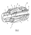
- connection means according to the invention which are described here, are intended to be implanted in a hydraulic circuit for connecting a pipe to an internal conduit of a member of this circuit.
- the connecting means comprise a connection generally designated 1 having a tubular body 2 which delimits an internal channel 3 and which has an end 4, here threaded to be screwed into a thread formed at a end of the internal conduit of the organ, and an end 5 at which the internal channel 3 opens by an opening 6 through which a nozzle 8 is intended to be introduced into an end section 7 of the internal channel 3.
- the tip 8 is tubular in shape and has an external diameter slightly smaller than the internal diameter of the end section 7.
- the tip 8 has an end recess 9 having an inner surface 28 flaring towards the front face of the endpiece from a bottom delimited by a convex frustoconical surface forming a shoulder 10.
- the end piece 8 has opposite the end recess 9 an end not visible in the figures, arranged to be mounted on one end of the pipe.
- the internal channel 3 of the body 2 is provided with means for sealingly holding the tip 8 therein.
- the sealing retaining means comprise a generally annular sealing element 11 received in a housing provided at the bottom of the end section 7 of the internal channel 3.
- the sealing element 11 comprises a ring 12 connecting to the housing.
- the ring 12 has a radial projecting axial face of which extends a terminal sleeve 13 and, opposite the end sleeve 13, an annular portion 14 beveled externally which is applied against a correspondingly shaped surface of the housing.
- the ring 12 comprises means for its clipping in the housing. These means are here formed by an annular bead 15 extending radially outwardly from the ring 12 in an annular cavity of the housing.
- the end sleeve 13 has an outside diameter between the minimum internal diameter and the maximum internal diameter of the counterbore 9 and a length slightly greater than the length of the counterbore 9.
- the end sleeve 13 has a concave frustoconical end face 16 for cooperating with the internal shoulder 10 and is externally provided with grooves 17.
- the radial face of the ring 12 projecting from which extends the end sleeve 13 comprises a planar groove 27 which surrounds the end sleeve 13 to receive the end of the end piece 8.
- the sealing element 11 is for example elastomeric thermoplastic TPU type of polyurethane or acrylonitrile butadiene elastomer (NBR), optionally filled with reinforcing fibers such as glass fibers.
- TPU elastomeric thermoplastic TPU type of polyurethane or acrylonitrile butadiene elastomer
- the sealed retaining means further comprise a split ring 18 having ends 19 provided with a bevel 20 on one inner side of the ring (see FIG. figure 5 ).
- the ring is radially and elastically deformable and has at rest an internal diameter at most equal to the outer diameter of the tip 8.
- the rod 18 is received in a groove 21 of the end section 7.
- the groove 21 has on the side of the opening 6 a concave frustoconical flank 22 and, on a side opposite the opening 6, a convex frustoconical flank 23
- the flanks 22 and 23 of the groove 21 are spaced a distance slightly greater than the diameter of the rod 18 so as to receive it with clearance between them and form an angle of about 40 ° with the central axis of the section end 7.
- the rod 18 is intended to be received in an external groove 24 of the nozzle 8 at its inner circumferential portion, the inner diameter of the rod 18 at rest being lower than the outer diameter of the nozzle 8.
- the external groove 24 is delimited laterally by flanks 24.1, 24.2 whose at least side 24.1 which is situated on the side of the end face of the end piece 8 and which is therefore opposite to the opening forms an angle of approximately 50 ° with a central axis of the tip 8.
- the leaktight retaining means also comprise an O-ring 25 received in a groove 26 formed in the end section near the opening 6.
- the O-ring 25 has an internal diameter slightly smaller than the external diameter of the nozzle 8.
- the nozzle 8 is introduced into the end section 7 of the internal channel 3 through the opening 6.
- the tip 8 is inserted by force into the O-ring 25 and pushes the ring 18 against the flank 23 of the groove 21.
- the flank 23 tends to spread the ring 18, which facilitates the passage of the tip 8 in this- this.
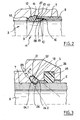
- the end sleeve 13 of the sealing element 11 penetrates into the end recess 9 of the endpiece 8 until the end face 16 of the end sleeve 13 comes into abutment against the internal shoulder 10 of the tip 8 and the end face of the tip 8 bears against the ring 12.
- the rod 18 is then received in the outer groove 24 of the nozzle 8 and the sealing member 12 tends to push back the end piece 8 so that the side of the outer groove 24 opposite the opening 6 pushes the ring 18 against the side 22 of the groove 21.
- the distance between the groove 24 and the end face of the endpiece 8 is slightly greater than the distance between the bottom of the planar groove 27 and the opening of the groove 21.
- the difference between, on the one hand, the distance between the end face of the nozzle 8 and the point of contact of the ring 18 with the sidewall 24.1 and, secondly, the distance between the bottom of the planar groove 27 and the point of con tact of the ring 18 with the flank 22 is such that the ring 12 is compressed axially when the rod 18 is received in the groove 24, which keeps the rod 18 in contact with the flanks 24.1 and 22.
- the flank 22 then exerts a necking force on the rod 18 which closes in the groove.
- the cooperation of said sidewall of the outer groove 24, the ring 18 and the sidewall 22 opposes the extraction of the endpiece 8 out of the connection 1.
- the sidewall convex frustoconical 24.1 of the external groove 24 of the nozzle 8 forms with the concave frustoconical flank 22 of the internal groove 21 of the fitting 1 an open angle ⁇ of about 10 ° towards the insertion opening 6 (c ' that is to say that the vertex of this angle ⁇ is on the side of the sealing element 11) which promotes a closure or necking of the rod 18 in the external groove 24 when an extraction force is exerted on the mouthpiece 8.
- the end of the nozzle 8 is received in the planar groove 27.
- the planar groove 27 divides the radial face of the ring 12 into an inner annular portion (extended by the end sleeve 13) and an annular portion outer end which encapsulate the end of the nozzle 8 thus ensuring the retention in position of the sealing member 11.
- This flat groove 27 extends substantially at the base of the bead 15 so that the insertion of the 8 in the flat throat 27 tends to support the ring 12 and thus opposes an escape of the bead 15 out of the annular cavity of the housing.
- the fluid When pressurizing the circuit, the fluid tends to apply the tapered portion 14 against the adjoining surface of the housing and the end sleeve 13 against the inner surface 28, which strengthens the seal.
- a tool 50 formed of a sleeve slotted longitudinally to allow its installation laterally on the tip 8.
- the sleeve has an end arranged to be slid between the outer surface of the nozzle 8 and the inner surface of the portion of the end portion 7 extending between the opening 6 and the flank 22 to be introduced into the rod 18 and / or to push the rod 18 against the flank 23 and, on the opposite side, an end provided externally with a flange for pressing the bushing into the fitting.
- the tip may be attached to a pipe end as in the embodiment described or the tip may be formed by the pipe end arranged accordingly.
- the end face of the end sleeve 13 and the shoulder 10 of the end recess 9 may also be formed of radial annular faces.
- the end sleeve 13 may also have a length less than that of the end recess 9 of the end piece 8 so that the connection is only sealed by the contact of the outer surface of the end sleeve 13 with the inner surface of the end chamber 9.
- the sealing element may have a configuration different from that described and for example be devoid of end sleeve 13. Furthermore, the end piece 8 may not comprise end recess 9 or have an end recess 9 having a cylindrical internal surface or any other form of revolution.
Landscapes
- Engineering & Computer Science (AREA)
- General Engineering & Computer Science (AREA)
- Mechanical Engineering (AREA)
- Quick-Acting Or Multi-Walled Pipe Joints (AREA)
- Non-Disconnectible Joints And Screw-Threaded Joints (AREA)
- Multi-Conductor Connections (AREA)
- Coupling Device And Connection With Printed Circuit (AREA)
Claims (4)
- Verbindungsvorrichtung, umfassend ein Verbindungsstück (1), das einen Innenkanal (3) begrenzt, von dem ein Endabschnitt (7) eine Einführöffnung (6) zum Einführen eines Rohrendes (8) hat und mit Mitteln versehen ist, um das Rohrende dort auf dichte Weise zu halten, wobei diese Mittel ein ringförmiges Dichtungselement (11) umfassen, das axial zusammengedrückt werden kann und derart in dem Verbindungsstück montiert ist, dass es eine Fläche aufweist, die als Anlage für eine Endfläche des Rohrendes dient, sowie ein ringförmiges Rückhalteelement (18), das radial und elastisch verformbar und in einer Innennut (21) des Endabschnittes derart aufgenommen ist, dass es einen inneren Umfangsabschnitt hat, der aus einer Öffnung der Innennut vorsteht, um in einer Außennut (24) des Rohrendes aufgenommen zu werden, dadurch gekennzeichnet, dass die Innennut auf der Seite der Öffnung des Endabschnittes eine konkave kegelstumpfförmige Flanke (22) hat, die Mittel zur Querschnittsverminderung des Rückhalteelements bildet, und auf einer der Öffnung entgegengesetzten Seite eine konvexe kegelstumpfförmige Flanke (23), die zur konkaven kegelstumpfförmigen Flanke einen solchen Abstand hat, dass das Rückhalteelement mit Spiel in der Innennut aufgenommen ist, und dass die Endfläche des Rohrendes und dessen Außennut einen Abstand zueinander haben, der geringfügig größer ist als der, der die Stirnfläche des Dichtungselements von der Öffnung der Innennut des Verbindungsstückes trennt.
- Verbindungsvorrichtung nach Anspruch 1, dadurch gekennzeichnet, dass die Außennut (24) des Rohrendes (8) auf der Seite einer Endfläche des Rohrendes (8) eine konvexe kegelstumpfförmige Flanke hat, die mit der konkaven kegelstumpfförmigen Flanke der Innennut des Verbindungsstückes (1) einen in Richtung der Einführöffnung offenen Winkel bildet.
- Verbindungsvorrichtung nach Anspruch 2, dadurch gekennzeichnet, dass der vorgenannte Winkel etwa 10° beträgt.
- Vorrichtung nach einem der Ansprüche 1 bis 3, dadurch gekennzeichnet, dass das Rückhalteelement ein geschlitzter Ring (18) ist, der auf seiner Innenseite abgeschrägte Enden (19) hat.
Applications Claiming Priority (3)
| Application Number | Priority Date | Filing Date | Title |
|---|---|---|---|
| FR0210981A FR2844335B1 (fr) | 2002-09-05 | 2002-09-05 | Moyens de connexion de conduits pour fluides haute pression |
| FR0210981 | 2002-09-05 | ||
| PCT/FR2003/002598 WO2004023013A2 (fr) | 2002-09-05 | 2003-08-28 | Moyens de connexion de conduits pour fluides haute pression |
Publications (2)
| Publication Number | Publication Date |
|---|---|
| EP1534983A2 EP1534983A2 (de) | 2005-06-01 |
| EP1534983B1 true EP1534983B1 (de) | 2009-08-12 |
Family
ID=31725851
Family Applications (1)
| Application Number | Title | Priority Date | Filing Date |
|---|---|---|---|
| EP03769532A Expired - Lifetime EP1534983B1 (de) | 2002-09-05 | 2003-08-28 | Verbindungsvorrichtung für unter hohem druck stehende leitungen |
Country Status (7)
| Country | Link |
|---|---|
| US (1) | US7264281B2 (de) |
| EP (1) | EP1534983B1 (de) |
| AT (1) | ATE439544T1 (de) |
| AU (1) | AU2003278219A1 (de) |
| DE (1) | DE60328794D1 (de) |
| FR (1) | FR2844335B1 (de) |
| WO (1) | WO2004023013A2 (de) |
Families Citing this family (18)
| Publication number | Priority date | Publication date | Assignee | Title |
|---|---|---|---|---|
| US7973936B2 (en) * | 2001-01-30 | 2011-07-05 | Board Of Trustees Of Michigan State University | Control system and apparatus for use with ultra-fast laser |
| US7533907B2 (en) * | 2005-03-11 | 2009-05-19 | The Gates Corporation Ip Law Dept. | Pressure activated disconnect lock coupling |
| FR2893698B1 (fr) * | 2005-11-18 | 2009-02-27 | Legris Sa | Raccord a couplage instantane |
| US8269408B2 (en) * | 2008-08-12 | 2012-09-18 | Helio Optoelectronics Corporation | LED base structure with embedded capacitor |
| US10221977B2 (en) | 2009-02-03 | 2019-03-05 | Aqseptence Group, Inc. | Pipe coupling |
| US8814219B2 (en) * | 2009-02-03 | 2014-08-26 | Bilfinger Water Technologies, Inc. | Push lock pipe connection system and disconnection tool |
| US8342579B2 (en) | 2009-02-03 | 2013-01-01 | Hennemann Thomas L | Push lock pipe connection system |
| US9810358B2 (en) | 2009-02-03 | 2017-11-07 | Aqseptence Group, Inc. | Male push lock pipe connection system |
| US8226128B2 (en) * | 2010-08-11 | 2012-07-24 | Ming-Yi Lee | Releasable nut-free C-clip secured pipe fitting |
| WO2012051481A1 (en) | 2010-10-15 | 2012-04-19 | Swagelok Company | Push to connect conduit fitting with ferrule |
| US9903518B2 (en) | 2013-10-24 | 2018-02-27 | Swagelok Company | Single action push to connect conduit fitting |
| EP3194828B1 (de) * | 2014-09-17 | 2021-01-20 | Parker Hannifin Manufacturing France SAS | Verbindungsvorrichtung und -verfahren für abgeschrägte rohre |
| US10458582B2 (en) | 2015-04-23 | 2019-10-29 | Swagelok Company | Single action push to connect conduit fitting with colleting |
| ES2755400T3 (es) | 2015-04-23 | 2020-04-22 | Swagelok Co | Conjunto de conector de empuje para conexión para un conducto |
| KR20210144674A (ko) | 2019-04-01 | 2021-11-30 | 스웨이지락 캄파니 | 푸시 투 커넥트 도관 이음쇠 어셈블리 및 장치 |
| CN112594444B (zh) * | 2020-11-26 | 2022-05-06 | 中核华辰工程管理有限公司 | 一种水厂至高山的供水主管道施工方法 |
| CN113028139B (zh) * | 2021-03-05 | 2022-04-01 | 江苏欣昌建设工程有限公司 | 雨污水管复合式接口及施工方法 |
| JP7695151B2 (ja) * | 2021-08-23 | 2025-06-18 | ニッタ株式会社 | 管継手及びその取付方法 |
Family Cites Families (10)
| Publication number | Priority date | Publication date | Assignee | Title |
|---|---|---|---|---|
| US3133755A (en) * | 1960-06-29 | 1964-05-19 | Stile Craft Mfg | Pin retainer construction for couplings |
| US3177018A (en) * | 1963-01-02 | 1965-04-06 | Aeroquip Corp | Snap ring coupling |
| DE2824943C2 (de) * | 1978-06-07 | 1986-07-31 | Armaturenfabrik Hermann Voss GmbH + Co, 5272 Wipperfürth | Anschlußvorrichtung für Bremsleitungen |
| US4294473A (en) * | 1979-03-16 | 1981-10-13 | Ekman Engineering Ag | Device at mutually lockable first and second parts |
| US5655796A (en) * | 1992-09-21 | 1997-08-12 | Proprietary Technology, Inc. | Tubular assembly and method of making same |
| JPH06147374A (ja) * | 1992-11-12 | 1994-05-27 | Tokyo Gas Co Ltd | 管継手 |
| EP0615089A1 (de) * | 1993-03-06 | 1994-09-14 | DEUTSCHE TECALEMIT GmbH | Lösbare Steckverbindung für Hochdruckleitungen |
| DE19533188A1 (de) * | 1995-09-08 | 1997-03-13 | Man Nutzfahrzeuge Ag | Lösbare Steckverbindung für Druckluftanlagen in Fahrzeugen |
| DE19932307A1 (de) * | 1999-07-10 | 2001-01-11 | Schaefer Stettiner Schrauben | Lösbare Steckverbindung für Rohrleitungen |
| DE10125499C1 (de) * | 2001-05-23 | 2002-08-14 | Schaefer Stettiner Schrauben | Steckverbindung, insbesondere für Rohrleitungen |
-
2002
- 2002-09-05 FR FR0210981A patent/FR2844335B1/fr not_active Expired - Fee Related
-
2003
- 2003-08-28 AT AT03769532T patent/ATE439544T1/de not_active IP Right Cessation
- 2003-08-28 DE DE60328794T patent/DE60328794D1/de not_active Expired - Lifetime
- 2003-08-28 AU AU2003278219A patent/AU2003278219A1/en not_active Abandoned
- 2003-08-28 WO PCT/FR2003/002598 patent/WO2004023013A2/fr not_active Ceased
- 2003-08-28 US US10/526,374 patent/US7264281B2/en not_active Expired - Fee Related
- 2003-08-28 EP EP03769532A patent/EP1534983B1/de not_active Expired - Lifetime
Also Published As
| Publication number | Publication date |
|---|---|
| WO2004023013A3 (fr) | 2004-05-27 |
| US7264281B2 (en) | 2007-09-04 |
| AU2003278219A1 (en) | 2004-03-29 |
| WO2004023013A2 (fr) | 2004-03-18 |
| DE60328794D1 (de) | 2009-09-24 |
| ATE439544T1 (de) | 2009-08-15 |
| AU2003278219A8 (en) | 2004-03-29 |
| FR2844335A1 (fr) | 2004-03-12 |
| US20060012171A1 (en) | 2006-01-19 |
| EP1534983A2 (de) | 2005-06-01 |
| FR2844335B1 (fr) | 2008-05-16 |
Similar Documents
| Publication | Publication Date | Title |
|---|---|---|
| EP1534983B1 (de) | Verbindungsvorrichtung für unter hohem druck stehende leitungen | |
| EP1087168B1 (de) | Vorrichtung zum Verbinden von einem Leitungsende mit einem Anschlussteil | |
| EP1427959B1 (de) | Schnellverbindungsvorrichtung | |
| EP2433044B1 (de) | Schnellverbindungsvorrichtung für grossen druckvariationen standhaltendenden flüssigkeitskreise | |
| EP2878873B1 (de) | Patronenartige schnellkupplungsvorrichtung | |
| EP2817548B1 (de) | Vorrichtung für abgedichtete kopplung ohne einen haltebereich | |
| CA2427203A1 (fr) | Dispositif de raccordement comportant des moyens de connexion instantanee d'une extremite de conduite a un organe et des moyens de protection de la connexion | |
| FR2958713A1 (fr) | Dispositif de raccordement d'un tube a un element de circuit, procede de montage d'une rondelle d'ancrage sur un corps d'un tel dispositif de raccordement et procede de demontage d'un tel dispositif | |
| EP0140171B1 (de) | Dichtung für Verbindungen von gusseisernen Rohren | |
| WO2001094798A1 (fr) | Insert d'implantation d'un raccord de tube dans un logement taraude | |
| EP2309164B1 (de) | Schnellkupplungsvorrichtung mit umgekehrtem Führungs- und Dichtungsbereich | |
| WO2010052386A1 (fr) | Dispositif de raccordement comportant un element d'etancheite | |
| EP1571383B1 (de) | Pressfitting mit einem schneidbaren Prüfring | |
| FR2844334A1 (fr) | Moyens de connexion de conduits pour fluides a haute pression | |
| FR2938625A1 (fr) | Dispositif de raccordement ayant des zones inversees d'etancheite et d'accrochage. | |
| FR2807134A1 (fr) | Dispositif d'etancheite et organe de raccordement d'une extremite de conduite a un element d'un circuit de transport de fluides | |
| EP1484542B1 (de) | Verbindungsvorrichtung für Hochdruckfluidleitungen | |
| FR2797674A1 (fr) | Dispositif de connexion d'un troncon de canalisation rigide a un organe | |
| EP1133654B1 (de) | Verbindungsvorrichtung einer metallischen rohrleitung | |
| EP1139002A1 (de) | Verfahren zur Trennung eines Rohrendes von einer Kupplung und Anschlussvorrichtung hierfür | |
| FR2573844A1 (fr) | Raccord rapide pour tuyau, notamment en matiere plastique | |
| FR2729736A1 (fr) | Dispositif de raccordement rapide d'un tube a un element rigide | |
| FR2827647A1 (fr) | Rondelle d'accrochage et dispositif de raccrochement comportant une telle rondelle | |
| FR3098886A1 (fr) | Dispositif de raccordement fluidique de type cartouche | |
| FR2711760A1 (fr) | Ensemble pour le raccordement d'un tuyau souple et raccord intermédiaire pour le raccordement d'un tel tuyau souple. |
Legal Events
| Date | Code | Title | Description |
|---|---|---|---|
| PUAI | Public reference made under article 153(3) epc to a published international application that has entered the european phase |
Free format text: ORIGINAL CODE: 0009012 |
|
| 17P | Request for examination filed |
Effective date: 20050215 |
|
| AK | Designated contracting states |
Kind code of ref document: A2 Designated state(s): AT BE BG CH CY CZ DE DK EE ES FI FR GB GR HU IE IT LI LU MC NL PT RO SE SI SK TR |
|
| AX | Request for extension of the european patent |
Extension state: AL LT LV MK |
|
| DAX | Request for extension of the european patent (deleted) | ||
| GRAP | Despatch of communication of intention to grant a patent |
Free format text: ORIGINAL CODE: EPIDOSNIGR1 |
|
| RAP1 | Party data changed (applicant data changed or rights of an application transferred) |
Owner name: LEGRIS SAS |
|
| GRAS | Grant fee paid |
Free format text: ORIGINAL CODE: EPIDOSNIGR3 |
|
| GRAA | (expected) grant |
Free format text: ORIGINAL CODE: 0009210 |
|
| AK | Designated contracting states |
Kind code of ref document: B1 Designated state(s): AT BE BG CH CY CZ DE DK EE ES FI FR GB GR HU IE IT LI LU MC NL PT RO SE SI SK TR |
|
| REG | Reference to a national code |
Ref country code: GB Ref legal event code: FG4D Free format text: NOT ENGLISH |
|
| REG | Reference to a national code |
Ref country code: CH Ref legal event code: EP |
|
| REG | Reference to a national code |
Ref country code: IE Ref legal event code: FG4D |
|
| REF | Corresponds to: |
Ref document number: 60328794 Country of ref document: DE Date of ref document: 20090924 Kind code of ref document: P |
|
| PG25 | Lapsed in a contracting state [announced via postgrant information from national office to epo] |
Ref country code: SE Free format text: LAPSE BECAUSE OF FAILURE TO SUBMIT A TRANSLATION OF THE DESCRIPTION OR TO PAY THE FEE WITHIN THE PRESCRIBED TIME-LIMIT Effective date: 20090812 Ref country code: AT Free format text: LAPSE BECAUSE OF FAILURE TO SUBMIT A TRANSLATION OF THE DESCRIPTION OR TO PAY THE FEE WITHIN THE PRESCRIBED TIME-LIMIT Effective date: 20090812 Ref country code: FI Free format text: LAPSE BECAUSE OF FAILURE TO SUBMIT A TRANSLATION OF THE DESCRIPTION OR TO PAY THE FEE WITHIN THE PRESCRIBED TIME-LIMIT Effective date: 20090812 Ref country code: ES Free format text: LAPSE BECAUSE OF FAILURE TO SUBMIT A TRANSLATION OF THE DESCRIPTION OR TO PAY THE FEE WITHIN THE PRESCRIBED TIME-LIMIT Effective date: 20091123 |
|
| NLV1 | Nl: lapsed or annulled due to failure to fulfill the requirements of art. 29p and 29m of the patents act | ||
| PG25 | Lapsed in a contracting state [announced via postgrant information from national office to epo] |
Ref country code: NL Free format text: LAPSE BECAUSE OF FAILURE TO SUBMIT A TRANSLATION OF THE DESCRIPTION OR TO PAY THE FEE WITHIN THE PRESCRIBED TIME-LIMIT Effective date: 20090812 Ref country code: SI Free format text: LAPSE BECAUSE OF FAILURE TO SUBMIT A TRANSLATION OF THE DESCRIPTION OR TO PAY THE FEE WITHIN THE PRESCRIBED TIME-LIMIT Effective date: 20090812 |
|
| BERE | Be: lapsed |
Owner name: LEGRIS SAS Effective date: 20090831 |
|
| REG | Reference to a national code |
Ref country code: IE Ref legal event code: FD4D |
|
| PG25 | Lapsed in a contracting state [announced via postgrant information from national office to epo] |
Ref country code: PT Free format text: LAPSE BECAUSE OF FAILURE TO SUBMIT A TRANSLATION OF THE DESCRIPTION OR TO PAY THE FEE WITHIN THE PRESCRIBED TIME-LIMIT Effective date: 20091212 Ref country code: MC Free format text: LAPSE BECAUSE OF NON-PAYMENT OF DUE FEES Effective date: 20090831 Ref country code: BG Free format text: LAPSE BECAUSE OF FAILURE TO SUBMIT A TRANSLATION OF THE DESCRIPTION OR TO PAY THE FEE WITHIN THE PRESCRIBED TIME-LIMIT Effective date: 20091112 |
|
| REG | Reference to a national code |
Ref country code: CH Ref legal event code: PL |
|
| PG25 | Lapsed in a contracting state [announced via postgrant information from national office to epo] |
Ref country code: RO Free format text: LAPSE BECAUSE OF FAILURE TO SUBMIT A TRANSLATION OF THE DESCRIPTION OR TO PAY THE FEE WITHIN THE PRESCRIBED TIME-LIMIT Effective date: 20090812 Ref country code: EE Free format text: LAPSE BECAUSE OF FAILURE TO SUBMIT A TRANSLATION OF THE DESCRIPTION OR TO PAY THE FEE WITHIN THE PRESCRIBED TIME-LIMIT Effective date: 20090812 Ref country code: DK Free format text: LAPSE BECAUSE OF FAILURE TO SUBMIT A TRANSLATION OF THE DESCRIPTION OR TO PAY THE FEE WITHIN THE PRESCRIBED TIME-LIMIT Effective date: 20090812 Ref country code: CH Free format text: LAPSE BECAUSE OF NON-PAYMENT OF DUE FEES Effective date: 20090831 Ref country code: LI Free format text: LAPSE BECAUSE OF NON-PAYMENT OF DUE FEES Effective date: 20090831 Ref country code: IE Free format text: LAPSE BECAUSE OF FAILURE TO SUBMIT A TRANSLATION OF THE DESCRIPTION OR TO PAY THE FEE WITHIN THE PRESCRIBED TIME-LIMIT Effective date: 20090812 Ref country code: CZ Free format text: LAPSE BECAUSE OF FAILURE TO SUBMIT A TRANSLATION OF THE DESCRIPTION OR TO PAY THE FEE WITHIN THE PRESCRIBED TIME-LIMIT Effective date: 20090812 |
|
| PG25 | Lapsed in a contracting state [announced via postgrant information from national office to epo] |
Ref country code: SK Free format text: LAPSE BECAUSE OF FAILURE TO SUBMIT A TRANSLATION OF THE DESCRIPTION OR TO PAY THE FEE WITHIN THE PRESCRIBED TIME-LIMIT Effective date: 20090812 |
|
| PLBE | No opposition filed within time limit |
Free format text: ORIGINAL CODE: 0009261 |
|
| STAA | Information on the status of an ep patent application or granted ep patent |
Free format text: STATUS: NO OPPOSITION FILED WITHIN TIME LIMIT |
|
| PG25 | Lapsed in a contracting state [announced via postgrant information from national office to epo] |
Ref country code: BE Free format text: LAPSE BECAUSE OF NON-PAYMENT OF DUE FEES Effective date: 20090831 |
|
| 26N | No opposition filed |
Effective date: 20100517 |
|
| GBPC | Gb: european patent ceased through non-payment of renewal fee |
Effective date: 20091112 |
|
| PG25 | Lapsed in a contracting state [announced via postgrant information from national office to epo] |
Ref country code: GR Free format text: LAPSE BECAUSE OF FAILURE TO SUBMIT A TRANSLATION OF THE DESCRIPTION OR TO PAY THE FEE WITHIN THE PRESCRIBED TIME-LIMIT Effective date: 20091113 |
|
| PG25 | Lapsed in a contracting state [announced via postgrant information from national office to epo] |
Ref country code: GB Free format text: LAPSE BECAUSE OF NON-PAYMENT OF DUE FEES Effective date: 20091112 |
|
| PG25 | Lapsed in a contracting state [announced via postgrant information from national office to epo] |
Ref country code: IT Free format text: LAPSE BECAUSE OF FAILURE TO SUBMIT A TRANSLATION OF THE DESCRIPTION OR TO PAY THE FEE WITHIN THE PRESCRIBED TIME-LIMIT Effective date: 20090812 |
|
| PG25 | Lapsed in a contracting state [announced via postgrant information from national office to epo] |
Ref country code: LU Free format text: LAPSE BECAUSE OF NON-PAYMENT OF DUE FEES Effective date: 20090828 |
|
| PG25 | Lapsed in a contracting state [announced via postgrant information from national office to epo] |
Ref country code: HU Free format text: LAPSE BECAUSE OF FAILURE TO SUBMIT A TRANSLATION OF THE DESCRIPTION OR TO PAY THE FEE WITHIN THE PRESCRIBED TIME-LIMIT Effective date: 20100213 |
|
| PG25 | Lapsed in a contracting state [announced via postgrant information from national office to epo] |
Ref country code: TR Free format text: LAPSE BECAUSE OF FAILURE TO SUBMIT A TRANSLATION OF THE DESCRIPTION OR TO PAY THE FEE WITHIN THE PRESCRIBED TIME-LIMIT Effective date: 20090812 |
|
| PG25 | Lapsed in a contracting state [announced via postgrant information from national office to epo] |
Ref country code: CY Free format text: LAPSE BECAUSE OF FAILURE TO SUBMIT A TRANSLATION OF THE DESCRIPTION OR TO PAY THE FEE WITHIN THE PRESCRIBED TIME-LIMIT Effective date: 20090812 |
|
| REG | Reference to a national code |
Ref country code: DE Ref legal event code: R082 Ref document number: 60328794 Country of ref document: DE Representative=s name: SCHAUMBURG & PARTNER PATENTANWAELTE GBR, DE Ref country code: DE Ref legal event code: R082 Ref document number: 60328794 Country of ref document: DE Representative=s name: SCHAUMBURG UND PARTNER PATENTANWAELTE MBB, DE |
|
| REG | Reference to a national code |
Ref country code: FR Ref legal event code: PLFP Year of fee payment: 14 |
|
| REG | Reference to a national code |
Ref country code: FR Ref legal event code: PLFP Year of fee payment: 15 |
|
| REG | Reference to a national code |
Ref country code: FR Ref legal event code: PLFP Year of fee payment: 16 |
|
| PGFP | Annual fee paid to national office [announced via postgrant information from national office to epo] |
Ref country code: DE Payment date: 20190807 Year of fee payment: 17 |
|
| REG | Reference to a national code |
Ref country code: DE Ref legal event code: R119 Ref document number: 60328794 Country of ref document: DE |
|
| PG25 | Lapsed in a contracting state [announced via postgrant information from national office to epo] |
Ref country code: DE Free format text: LAPSE BECAUSE OF NON-PAYMENT OF DUE FEES Effective date: 20210302 |
|
| PGFP | Annual fee paid to national office [announced via postgrant information from national office to epo] |
Ref country code: FR Payment date: 20220818 Year of fee payment: 20 |