EP1534558B1 - Lastträger für fahrzeuge - Google Patents
Lastträger für fahrzeuge Download PDFInfo
- Publication number
- EP1534558B1 EP1534558B1 EP03784402A EP03784402A EP1534558B1 EP 1534558 B1 EP1534558 B1 EP 1534558B1 EP 03784402 A EP03784402 A EP 03784402A EP 03784402 A EP03784402 A EP 03784402A EP 1534558 B1 EP1534558 B1 EP 1534558B1
- Authority
- EP
- European Patent Office
- Prior art keywords
- frame body
- shaped
- vehicle
- anchoring
- brackets
- Prior art date
- Legal status (The legal status is an assumption and is not a legal conclusion. Google has not performed a legal analysis and makes no representation as to the accuracy of the status listed.)
- Expired - Lifetime
Links
- 238000004873 anchoring Methods 0.000 claims description 9
- 230000000284 resting effect Effects 0.000 claims description 8
- 230000035939 shock Effects 0.000 claims 1
- 239000000969 carrier Substances 0.000 description 5
- 230000000903 blocking effect Effects 0.000 description 4
- 238000004519 manufacturing process Methods 0.000 description 4
- 230000001105 regulatory effect Effects 0.000 description 2
Images


Classifications
-
- B—PERFORMING OPERATIONS; TRANSPORTING
- B60—VEHICLES IN GENERAL
- B60R—VEHICLES, VEHICLE FITTINGS, OR VEHICLE PARTS, NOT OTHERWISE PROVIDED FOR
- B60R9/00—Supplementary fittings on vehicle exterior for carrying loads, e.g. luggage, sports gear or the like
- B60R9/06—Supplementary fittings on vehicle exterior for carrying loads, e.g. luggage, sports gear or the like at vehicle front or rear
-
- B—PERFORMING OPERATIONS; TRANSPORTING
- B60—VEHICLES IN GENERAL
- B60R—VEHICLES, VEHICLE FITTINGS, OR VEHICLE PARTS, NOT OTHERWISE PROVIDED FOR
- B60R9/00—Supplementary fittings on vehicle exterior for carrying loads, e.g. luggage, sports gear or the like
- B60R9/08—Supplementary fittings on vehicle exterior for carrying loads, e.g. luggage, sports gear or the like specially adapted for sports gear
- B60R9/10—Supplementary fittings on vehicle exterior for carrying loads, e.g. luggage, sports gear or the like specially adapted for sports gear for cycles
Definitions
- the invention relates to a luggage carrier for vehicles, i. e. a device suitable for receiving loads, preferably applicable to the rear portion of said vehicles at a door or a boot cowling, provided with an adjusting system that enables said luggage carrier to conform to vehicles with different sizes and shapes.
- the rear luggage carriers a vailable at present substantially differ one from the other on the basis of the technical solutions chosen for adapting a same luggage carrier to the plurality of shapes and size s of the attachment regions of the vehicles generally available on the market.
- WO 00/76809 suggests a luggage carrier comprising frame sections mutually connected by means of telescopic tubes; in this case, a variation of the length of the luggage carrier is obtained making the portions of the frame to telescopically slide one into the other, this enables to engage hook portions of opposed ends of each section with corresponding edge portions of the vehicle hatchback.
- the user is requested to apply a certain force for causing the sections to mutually slide as well as for blocking said sections in the desired position by means of a lever closing device, that results in a clear disadvantage.
- a so structured device has short handling in use as well as a substantial complexity in fabrication due to the necessity to provide components (telescopic elements of the frame, closing lever) that increase fabrication time and fabrication costs.
- the first part of the frame below ends with a couple of supporting elements arranged for being positioned on the rear of the vehicle bumper or on the lower edge of the rear vehicle hatchback, thus actually impeding the opening of the vehicle hatchback after the luggage carrier has been mounted.
- a resting clamp for resting on the.rear window of the vehicle, or on the bonnet of the rear boot.
- Elements for supporting a load for example a bicycle, are hinged at the top of the second part of frame.
- Fixing the luggage carrier is particularly laborious, because it is necessary to act to position and stretch individually the numerous belts, and this implies a remarkable time and energies loss.
- the luggage carriers of this kind are furthermore constructionally complex, because it is necessary to arrange numerous components to obtain first and second parts of frame, elements for receiving the load, as well as devices for blocking the latter in the use position.
- US 3927811 discloses a collapsible carrier for bicycles, luggage and the like, including two substantially U-shaped members pivotally connected.
- the carrier is provided with latching slide means that enable the two members to be maintained at right angles when in use or, alternatively, to be folded for storage and transport.
- attaching straps are provided that are fastened to the two members and that have to be individually and manually stretched, which results fatiguing and time-wasting for an user.
- An object of the present invention is to improve the luggage carriers for vehicles.
- a further object is to provide the user with a luggage carrier that can be easily mounted and dismounted from a vehicle.
- Another object is to provide a luggage carrier provided with an actuating device for anchoring on and dismounting from a vehicle that is easy to be reached.
- a further other object is to simplify the manual operation required to the user during the phase of fitting the luggage carrier on the sizes and shapes of the vehicle whereon it is mounted.
- a still further object is to reduce the number of components forming of the luggage carrier, thus reducing time and costs of production.
- the invention provides an apparatus for transporting loads as defined in Claim 1.
- the anchoring means comprises hooking elements suitable to wound a significant edge portion of said part of vehicle.
- the fixing means are preferably interposed between the anchoring means and the first frame body means. Still preferably, the fixing means can be obtained by using connecting members, flexible or not flexible - such strap, pierced strap (in particular metallic) - tie-rod, preferably of the screw type, toothed belts.
- the connecting members can be coupled to stretching devices known in se, such: ratchets, windlass, stretchers, and similar.
- first and second frame body means After the opening angle comprised between first and second frame body means has been manually regulated so as to fit the shape of the vehicle part on which the device has to mounted, and after the first and second frame body means has been blocked in their mutual position that define such angle, it is possible to act on the afore-said fixing means for stretching the same, and thus assuring a stable positioning of the apparatus on the vehicle.
- the load supporting means can be obtained so as to form a single body with the frame body means.
- the here above said supporting means is itself arranged in a suitable load receiving position and it has not to be further regulated by the user.
- the Figure 1 shows a luggage carrier 1 mounted at the rear end of a vehicle D, represented by dashed line, and comprising a frame body 2 and a further frame body 3.
- the frame body 2 comprises a U-shaped portion 2', whose two ends extend over two arms 7, each one of which is provided with an extractable portion 8, provided with through holes 9; once the luggage carrier 1 has been assembled, the U-shaped portion 2' shows the arms 7 turned downwards; between the U-shaped portion 2' and the arms 7 there is defined an obtuse angle G, not shown.
- the U-shaped portion 2' contains, near each one of its parallel sides, a slip joint 5 comprising a pair of discs frontally toothed reciprocally seizing up.
- the slip joint 5 is interposed between the frame body 2 and the further frame body 3, and enables to articulate the two afore-said frame bodies as well as to blocking in preset reciprocal angular position.
- the extractable portion 8 can be received for a longer or shorter portion of its length into the arm 7 and can be fixed in the preset position by means of a bolt, not shown, suitable for being positioned at one of the through holes 9.
- a bolt not shown
- the length of any arm 7 can be changed and in particular can be made suitable for being mounted on vehicle portions that, due to their extend, would be otherwise unreachable.
- the extractable portion 8 further comprises an anchoring appendage 10, terminating with a curved end 11 suitable for hooking with a bottom edge E' of the rear door E or a of bonnet boot, not shown, of a vehicle D.
- a C-shaped element 12 arranged so as to have its longer rectilinear portion facing in the opposed direction with respect to the rear door E.
- the C-shaped element 12 engages with each of the arms 7 by means of a further hinge 5', provided with a clutch 4', the latter comprising a knob 6.
- the knob 6 enables to reciprocally tighten the two discs of the clutch 4', so blocking the hinge 5' in the requested position.
- the hinge 5' enables the C-shaped element 12 to be moved from a retracted position H to an extended position H', represented by dashed line. That enables to prevent that a particularly voluminous object mounted on the luggage carrier, for example a bicycle, can accidentally hit and then damage the surface of the rear door E or of the rear bumper, not shown, of the vehicle D.
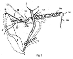
- the further frame body 3, as depicted in the Figures 1 to 3, has a further U-shaped portion 3', whose two ends extend, by means of two curved sections 13, over two brackets 13'; each of the brackets 13' defines with the U-shaped portion 3' a further obtuse angle G', not shown.
- Each of the brackets 13' further contains a set of grooves 14a, suitable for being advantageously used as rack 14 whereon bicycles, having frame provided with central crossbar, can be received. With the rack 14 there is associated a tightening tape 14b suitable for holding in position the frame crossbar, received in every groove 14a.
- the slip joints 5 are arranged at the intersection between the two portions of the further frame body 3 comprised between the two curved sections 13 and the two racks 14.
- the further frame body 3 receives in its further U-shaped portion 3' at least a resting element 15, preferably in form of resilient cylinder having smooth surface; by means of the resting element 15 the further frame body 3 can be applied on the rear door E without damaging the external surface of the latter.
- Each fixing group 19 comprises dragging means 23 received in seat means 34, being the afore-said seat means 34 delimited by a couple of sidewalls 24, 24' that have convex outline and whose relative bases are integral with an intermediate plate 35.
- the intermediate plate 35 is made integral with the median segment M by means of a washer bolt 36.
- the dragging means 23 comprises in turn a shell 25, with an approximately C-shaped section, that is made integral with the couple of sidewalls 24, 24' by means of a plurality of protruding elements 25'.
- the shell 25 internally receives an operating screw 26, vertically oriented and provided at its end opposed to the median plate 35 with a nut 27.
- the operating screw 26 engages with a toothed wheel 29 supported by the sidewalls 24, 24' and provided with tooth 29' engaged in equidistant holes 30'' obtained in a pierced portion 30' of a strap 30 that is interposed between the toothed wheel 29 of the dragging means 23 and the further frame body 3'.
- the strap 30 comprises a pierced portion 30' and a unpierced portion 31 partially covered by an anti-abrasive sheathing 16.
- the free end 31' of the unpierced portion 31 is integral with a curved plate 18, suitable to hook to a upper edge C of the rear door E or of a bonnet boot, not shown, of a vehicle D.
- the strap 30 By rotating the nut 27 in a direction, the strap 30 is moved along a direction F away from the curved plate 18 and then stretched, this enables to firmly anchor the curved plate 18 to the bodywork of the vehicle D and to firmly maintain the luggage carrier 1 in a position suitable to be used.
- the pierced strap 30 is moved in a direction F oriented towards the curved plate 18. In this way, the strap 30 is loosen, this enables the curved plate 18 to be unhooked from the upper edge C of the rear door E or of a bonnet boot, not shown, of a vehicle D and to subsequently to remove the luggage carrier 1.
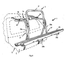
- the further frame body 3a comprises, instead of the brackets 14, another further U-shaped portion 3b extending, at both the ends, over an L-shaped loading element 27.
- Each one of the L-shaped loading elements 27 comprises a vertical bar 28a and a horizontal bar 28b, mutually connected at right angle.
- Each one of the vertical rod 28a engages with the frame body 2 by means of the slip joint 5 previously described.
- the two horizontal bars 28b receive a pair of profiled elements 29, orthogonally arranged with respect to said horizontal bars 28b and having a roughly C-shaped section.
- the luggage carrier 1 can be transported bicycles also having a frame unprovided with central crossbar, such as for example the ladies' bicycles.
Landscapes
- Engineering & Computer Science (AREA)
- Mechanical Engineering (AREA)
- Fittings On The Vehicle Exterior For Carrying Loads, And Devices For Holding Or Mounting Articles (AREA)
- Vehicle Step Arrangements And Article Storage (AREA)
- Fats And Perfumes (AREA)
- Catalysts (AREA)
- Handcart (AREA)
- Transmission Devices (AREA)
Claims (20)
- Vorrichtung zum Transportieren von Lasten, die zur Befestigung an einem Fahrzeug (D) geeignet ist, mit ersten Rahmenkörpermitteln (2) und zweiten Rahmenkörpermitteln (3), die über Gelenkmittel (5) miteinander gekoppelt sind und die ausgebildet sind, um über Ankermittel (10, 11, 16, 18, 30) mit einander gegenüberliegenden Kanten (C, E') einer Tür (E) des Fahrzeugs (D) verbunden zu werden, wobei die Ankermittel (10, 11, 16, 18, 30) Riemenmittel (30) aufweisen, und mit Lasttragemitteln (14), die mit den ersten und/oder zweiten Rahmenkörpermitteln (2, 3) verbunden sind, dadurch gekennzeichnet, dass an den Rahmenkörpermitteln (2, 3) Befestigungsmittel (19) angeordnet sind, die mit einem Wirkglied (23) versehen sind, das mit den Riemenmitteln (30) zusammenwirkt, so dass die Riemenmittel (30) durch eine Betätigung an dem Wirkglied (23) alternativ in eine oder aus einer vorgesehenen Ankerzone (C) der gegenüberliegenden Kanten (C, E') bewegt werden können.
- Vorrichtung nach Anspruch 1, wobei die Lasttragemittel (14) mit den ersten und/oder zweiten Rahmenkörpermitteln (2, 3) einen einzigen Körper bilden.
- Vorrichtung nach Anspruch 2, wobei die Lasttragemittel (14) auf Verlängerungen der zweiten Rahmenkörpermittel (3) über die Gelenkmittel (5) hinaus angeordnet sind.
- Vorrichtung nach einem der vorhergehenden Ansprüche, wobei die ersten Rahmenkörpermittel (2) einen U-förmigen Abschnitt (2') aufweisen.
- Vorrichtung nach Anspruch 4, wobei sich der U-förmige Abschnitt (2') auf Armmittel (7) erstreckt.
- Vorrichtung nach Anspruch 5, wobei der U-förmige Abschnitt (2') und die Armmittel (7) so angeordnet sind, dass sie einen stumpfen Winkel (G) festlegen.
- Vorrichtung nach Anspruch 5 oder 6, wobei die Armmittel (7) mit an den Enden aufgesetzten Ankermitteln (10) auslaufen.
- Vorrichtung nach einem der Ansprüche 5 bis 7, wobei die Armmittel (7) teleskopartige Abschnittsteile (8) aufweisen.
- Vorrichtung nach einem der Ansprüche 5 bis 8, wobei die Armmittel (7) Endabschnitte von C-förmigen Lastdistanzhaltemitteln (12) in einer einstellbaren Art und Weise tragen.
- Vorrichtung nach einem der vorhergehenden Ansprüche, wobei die zweiten Rahmenkörpermittel (3) einen weiteren U-förmigen Abschnitt (3') aufweisen.
- Vorrichtung nach Anspruch 10, wobei der weitere U-förmige Abschnitt (3') Stützmittel (25) aus einem stoßfesten Material aufweist.
- Vorrichtung nach einem der vorhergehenden Ansprüche, wobei die Lasttragemittel (14) Kragarmmittel (13') beinhalten, die an der Verlängerung des weiteren U-förmigen Abschnitts (3') angeordnet sind.
- Vorrichtung nach Anspruch 12, wobei die Kragarmmittel (13') und der weitere U-förmige Abschnitt (3') so ausgebildet sind, dass sie einen weiteren stumpfen Winkel (G) bilden.
- Vorrichtung nach Anspruch 12 oder 13, wobei die Kragarmmittel (13') Aufhängemittel (14) aufnehmen.
- Vorrichtung nach einem der Ansprüche 12 bis 14, wobei sich die Kragarmmittel (13') auf L-förmigen Lastmitteln (27) erstrecken, die ein vertikales Stangenmittel (28a) und ein horizontales Stangenmittel (28b) aufweisen, die unter einem Winkel miteinander verbunden sind.
- Vorrichtung nach Anspruch 15, wobei das horizontale Stangenmittel (28b) profilierte Elemente (29) aufnimmt, die in Bezug auf das horizontale Stangenmittel (28b) quer angeordnet sind.
- Vorrichtung nach einem der vorhergehenden Ansprüche, wobei die Haltemittel (19) zwischen den Ankermitteln (16) und den zweiten Rahmenkörpermitteln (3) angeordnet sind.
- Vorrichtung nach einem der vorhergehenden Ansprüche, wobei die Haltemittel (19) aus einer Gruppe ausgewählt sind, die Folgendes beinhaltet: flexible Verbindungsglieder, nichtflexible Verbindungsglieder, Riemen, schraubbare Zugstreben, Winden, Ratschen, Zahnriemen.
- Vorrichtung nach einem der vorhergehenden Ansprüche, wobei die Haltemittel (19) Riemen (30) aufweisen, die mit Löchern (39'') versehen sind, in die Zähne (29') eines Zahnrades (29) eingreifen, das mit Hilfe einer Bedienschraube (26) gedreht werden kann.
- Vorrichtung nach einem der Ansprüche 12 bis 19, wobei zwischen den Kragarmmitteln (13') und jedem der weiteren U-förmigen Abschnitte (3') ein gekrümmter Abschnitt (13) angeordnet ist.
Applications Claiming Priority (3)
| Application Number | Priority Date | Filing Date | Title |
|---|---|---|---|
| IT000231A ITMO20020231A1 (it) | 2002-08-09 | 2002-08-09 | Portapacchi per veicoli. |
| ITMO20020231 | 2002-08-09 | ||
| PCT/IB2003/003535 WO2004014698A1 (en) | 2002-08-09 | 2003-08-06 | Load carrier for vehicles |
Publications (2)
| Publication Number | Publication Date |
|---|---|
| EP1534558A1 EP1534558A1 (de) | 2005-06-01 |
| EP1534558B1 true EP1534558B1 (de) | 2007-02-21 |
Family
ID=31503952
Family Applications (1)
| Application Number | Title | Priority Date | Filing Date |
|---|---|---|---|
| EP03784402A Expired - Lifetime EP1534558B1 (de) | 2002-08-09 | 2003-08-06 | Lastträger für fahrzeuge |
Country Status (6)
| Country | Link |
|---|---|
| EP (1) | EP1534558B1 (de) |
| AT (1) | ATE354499T1 (de) |
| AU (1) | AU2003249542A1 (de) |
| DE (2) | DE60312003T2 (de) |
| IT (1) | ITMO20020231A1 (de) |
| WO (1) | WO2004014698A1 (de) |
Families Citing this family (3)
| Publication number | Priority date | Publication date | Assignee | Title |
|---|---|---|---|---|
| JP2006504567A (ja) * | 2002-10-31 | 2006-02-09 | ペドリーニ、ファビオ | 車載用具キャリア |
| DE102007035135B3 (de) * | 2007-07-25 | 2009-02-19 | Eufab Gmbh | Lastenträger zur Anbringung an der Heckklappe eines Fahrzeuges |
| US20120298707A1 (en) * | 2011-01-21 | 2012-11-29 | Yakima Products, Inc. | Adjustable trunk racks for carrying bicycles |
Family Cites Families (11)
| Publication number | Priority date | Publication date | Assignee | Title |
|---|---|---|---|---|
| US3710999A (en) * | 1970-11-05 | 1973-01-16 | R Allen | Automobile carrier |
| US3927811A (en) * | 1974-05-06 | 1975-12-23 | Henry Nussbaum | Collapsible carrier for bicycles |
| US4336897A (en) * | 1980-12-03 | 1982-06-29 | Luck Arthur J | Rack for bicycles |
| US4709840A (en) * | 1985-10-18 | 1987-12-01 | Allen Richard A | Universal folding carrier |
| US5056699A (en) | 1986-12-31 | 1991-10-15 | Bell Helmets, Inc. | Bicycle carrier |
| FR2668435B1 (fr) * | 1990-10-26 | 1995-05-12 | Mottez Sa | Porte-velo de voiture destine a etre fixe a l'arriere d'un vehicule pour assurer le transport d'une bicyclette. |
| US5211323A (en) | 1992-02-03 | 1993-05-18 | Industri Ab Thule | Bicycle carrier adapted to be mounted on the back of a vehicle |
| US5435472A (en) * | 1992-09-30 | 1995-07-25 | Allen; Richard A. | Folding carrier and securing system therefor |
| SE516070C2 (sv) | 1999-05-28 | 2001-11-12 | Thule Ind Ab | Fordonsburen lastbärare |
| US6286738B1 (en) | 1999-12-17 | 2001-09-11 | Yakima Products, Inc. | Bicycle carrier |
| ITMO20020051A1 (it) * | 2002-02-28 | 2003-08-28 | Menabo S R L Flli | Portapacchi per veicoli |
-
2002
- 2002-08-09 IT IT000231A patent/ITMO20020231A1/it unknown
-
2003
- 2003-08-06 DE DE60312003T patent/DE60312003T2/de not_active Expired - Lifetime
- 2003-08-06 EP EP03784402A patent/EP1534558B1/de not_active Expired - Lifetime
- 2003-08-06 DE DE20321418U patent/DE20321418U1/de not_active Expired - Lifetime
- 2003-08-06 AU AU2003249542A patent/AU2003249542A1/en not_active Abandoned
- 2003-08-06 WO PCT/IB2003/003535 patent/WO2004014698A1/en not_active Ceased
- 2003-08-06 AT AT03784402T patent/ATE354499T1/de active
Also Published As
| Publication number | Publication date |
|---|---|
| DE20321418U1 (de) | 2007-03-08 |
| AU2003249542A1 (en) | 2004-02-25 |
| DE60312003T2 (de) | 2007-05-31 |
| WO2004014698A1 (en) | 2004-02-19 |
| ATE354499T1 (de) | 2007-03-15 |
| DE60312003D1 (de) | 2007-04-05 |
| EP1534558A1 (de) | 2005-06-01 |
| ITMO20020231A1 (it) | 2004-02-10 |
Similar Documents
| Publication | Publication Date | Title |
|---|---|---|
| US5833074A (en) | Fast-loading, protective bicycle rack | |
| US5065921A (en) | Bicycle rack for mounting on a van | |
| US4997116A (en) | Rear mountable carrier rack | |
| US6015074A (en) | Roof rack for a vehicle | |
| US8678459B1 (en) | Truck load protection apparatus | |
| US5860691A (en) | Apparatus for covering a vehicle cargo area | |
| EP1104718A2 (de) | Dachlastträger | |
| US20080142559A1 (en) | External bicycle rack integrated within a vehicle | |
| EP0563463B1 (de) | Vorrichtung zum Be- und Entladen sowie zum Transportieren von Fahrrädern auf einem mit Längsträgern ausgerüsteten Kraftfahrzeugdach | |
| US6257637B1 (en) | Removable tailgate extender net | |
| EP0717686B1 (de) | Gepäckträger | |
| WO2009158360A1 (en) | Rack tower for securing crossbars on top of a vehicle | |
| WO2012122130A2 (en) | Ladder rack system | |
| US4709840A (en) | Universal folding carrier | |
| WO2010064233A1 (en) | Car rack | |
| US20170028928A1 (en) | Rooftop Bike Rack System | |
| US7527157B2 (en) | Wheel barrow rack and method of storing a wheel barrow | |
| US5826769A (en) | Multi-purpose folding carrier | |
| KR100940449B1 (ko) | 승용차용 탈부착 후방캐리어 | |
| US10800342B2 (en) | Bike rack | |
| EP1534558A1 (de) | LASTTRûGER FÜR FAHRZEUGE | |
| US5836492A (en) | Tire mountable folding carrier | |
| EP1679231B1 (de) | Gepäckträger für ein fahrzeug | |
| KR20090129375A (ko) | 차량 물품 캐리어 | |
| WO2016005828A1 (en) | A parking station for motorcycles |
Legal Events
| Date | Code | Title | Description |
|---|---|---|---|
| PUAI | Public reference made under article 153(3) epc to a published international application that has entered the european phase |
Free format text: ORIGINAL CODE: 0009012 |
|
| 17P | Request for examination filed |
Effective date: 20050307 |
|
| AK | Designated contracting states |
Kind code of ref document: A1 Designated state(s): AT BE BG CH CY CZ DE DK EE ES FI FR GB GR HU IE IT LI LU MC NL PT RO SE SI SK TR |
|
| AX | Request for extension of the european patent |
Extension state: AL LT LV MK |
|
| DAX | Request for extension of the european patent (deleted) | ||
| GRAP | Despatch of communication of intention to grant a patent |
Free format text: ORIGINAL CODE: EPIDOSNIGR1 |
|
| GRAS | Grant fee paid |
Free format text: ORIGINAL CODE: EPIDOSNIGR3 |
|
| GRAA | (expected) grant |
Free format text: ORIGINAL CODE: 0009210 |
|
| AK | Designated contracting states |
Kind code of ref document: B1 Designated state(s): AT BE BG CH CY CZ DE DK EE ES FI FR GB GR HU IE IT LI LU MC NL PT RO SE SI SK TR |
|
| PG25 | Lapsed in a contracting state [announced via postgrant information from national office to epo] |
Ref country code: SI Free format text: LAPSE BECAUSE OF FAILURE TO SUBMIT A TRANSLATION OF THE DESCRIPTION OR TO PAY THE FEE WITHIN THE PRESCRIBED TIME-LIMIT Effective date: 20070221 Ref country code: DK Free format text: LAPSE BECAUSE OF FAILURE TO SUBMIT A TRANSLATION OF THE DESCRIPTION OR TO PAY THE FEE WITHIN THE PRESCRIBED TIME-LIMIT Effective date: 20070221 Ref country code: FI Free format text: LAPSE BECAUSE OF FAILURE TO SUBMIT A TRANSLATION OF THE DESCRIPTION OR TO PAY THE FEE WITHIN THE PRESCRIBED TIME-LIMIT Effective date: 20070221 |
|
| REG | Reference to a national code |
Ref country code: GB Ref legal event code: FG4D |
|
| REG | Reference to a national code |
Ref country code: CH Ref legal event code: NV Representative=s name: FIAMMENGHI-FIAMMENGHI Ref country code: CH Ref legal event code: EP |
|
| REF | Corresponds to: |
Ref document number: 60312003 Country of ref document: DE Date of ref document: 20070405 Kind code of ref document: P |
|
| REG | Reference to a national code |
Ref country code: IE Ref legal event code: FG4D |
|
| PG25 | Lapsed in a contracting state [announced via postgrant information from national office to epo] |
Ref country code: SE Free format text: LAPSE BECAUSE OF FAILURE TO SUBMIT A TRANSLATION OF THE DESCRIPTION OR TO PAY THE FEE WITHIN THE PRESCRIBED TIME-LIMIT Effective date: 20070521 |
|
| PG25 | Lapsed in a contracting state [announced via postgrant information from national office to epo] |
Ref country code: BG Free format text: LAPSE BECAUSE OF EXPIRATION OF PROTECTION Effective date: 20070522 |
|
| PG25 | Lapsed in a contracting state [announced via postgrant information from national office to epo] |
Ref country code: ES Free format text: LAPSE BECAUSE OF FAILURE TO SUBMIT A TRANSLATION OF THE DESCRIPTION OR TO PAY THE FEE WITHIN THE PRESCRIBED TIME-LIMIT Effective date: 20070601 |
|
| ET | Fr: translation filed | ||
| PG25 | Lapsed in a contracting state [announced via postgrant information from national office to epo] |
Ref country code: PT Free format text: LAPSE BECAUSE OF FAILURE TO SUBMIT A TRANSLATION OF THE DESCRIPTION OR TO PAY THE FEE WITHIN THE PRESCRIBED TIME-LIMIT Effective date: 20070723 |
|
| PLBI | Opposition filed |
Free format text: ORIGINAL CODE: 0009260 |
|
| 26 | Opposition filed |
Opponent name: EUFAB GMBH Effective date: 20070915 |
|
| PG25 | Lapsed in a contracting state [announced via postgrant information from national office to epo] |
Ref country code: SK Free format text: LAPSE BECAUSE OF FAILURE TO SUBMIT A TRANSLATION OF THE DESCRIPTION OR TO PAY THE FEE WITHIN THE PRESCRIBED TIME-LIMIT Effective date: 20070221 |
|
| NLR1 | Nl: opposition has been filed with the epo |
Opponent name: EUFAB GMBH |
|
| PG25 | Lapsed in a contracting state [announced via postgrant information from national office to epo] |
Ref country code: RO Free format text: LAPSE BECAUSE OF FAILURE TO SUBMIT A TRANSLATION OF THE DESCRIPTION OR TO PAY THE FEE WITHIN THE PRESCRIBED TIME-LIMIT Effective date: 20070221 |
|
| PLAX | Notice of opposition and request to file observation + time limit sent |
Free format text: ORIGINAL CODE: EPIDOSNOBS2 |
|
| PLBP | Opposition withdrawn |
Free format text: ORIGINAL CODE: 0009264 |
|
| PG25 | Lapsed in a contracting state [announced via postgrant information from national office to epo] |
Ref country code: MC Free format text: LAPSE BECAUSE OF NON-PAYMENT OF DUE FEES Effective date: 20070831 Ref country code: GR Free format text: LAPSE BECAUSE OF FAILURE TO SUBMIT A TRANSLATION OF THE DESCRIPTION OR TO PAY THE FEE WITHIN THE PRESCRIBED TIME-LIMIT Effective date: 20070522 Ref country code: IT Free format text: LAPSE BECAUSE OF NON-PAYMENT OF DUE FEES Effective date: 20070806 |
|
| PLBD | Termination of opposition procedure: decision despatched |
Free format text: ORIGINAL CODE: EPIDOSNOPC1 |
|
| PLBB | Reply of patent proprietor to notice(s) of opposition received |
Free format text: ORIGINAL CODE: EPIDOSNOBS3 |
|
| PLBM | Termination of opposition procedure: date of legal effect published |
Free format text: ORIGINAL CODE: 0009276 |
|
| STAA | Information on the status of an ep patent application or granted ep patent |
Free format text: STATUS: OPPOSITION PROCEDURE CLOSED |
|
| 27C | Opposition proceedings terminated |
Effective date: 20080622 |
|
| PG25 | Lapsed in a contracting state [announced via postgrant information from national office to epo] |
Ref country code: IE Free format text: LAPSE BECAUSE OF NON-PAYMENT OF DUE FEES Effective date: 20070807 |
|
| NLR2 | Nl: decision of opposition |
Effective date: 20080622 |
|
| PG25 | Lapsed in a contracting state [announced via postgrant information from national office to epo] |
Ref country code: EE Free format text: LAPSE BECAUSE OF FAILURE TO SUBMIT A TRANSLATION OF THE DESCRIPTION OR TO PAY THE FEE WITHIN THE PRESCRIBED TIME-LIMIT Effective date: 20070221 |
|
| PG25 | Lapsed in a contracting state [announced via postgrant information from national office to epo] |
Ref country code: CY Free format text: LAPSE BECAUSE OF FAILURE TO SUBMIT A TRANSLATION OF THE DESCRIPTION OR TO PAY THE FEE WITHIN THE PRESCRIBED TIME-LIMIT Effective date: 20070221 |
|
| PG25 | Lapsed in a contracting state [announced via postgrant information from national office to epo] |
Ref country code: LU Free format text: LAPSE BECAUSE OF NON-PAYMENT OF DUE FEES Effective date: 20070806 |
|
| PG25 | Lapsed in a contracting state [announced via postgrant information from national office to epo] |
Ref country code: HU Free format text: LAPSE BECAUSE OF FAILURE TO SUBMIT A TRANSLATION OF THE DESCRIPTION OR TO PAY THE FEE WITHIN THE PRESCRIBED TIME-LIMIT Effective date: 20070822 Ref country code: TR Free format text: LAPSE BECAUSE OF FAILURE TO SUBMIT A TRANSLATION OF THE DESCRIPTION OR TO PAY THE FEE WITHIN THE PRESCRIBED TIME-LIMIT Effective date: 20070221 |
|
| PGFP | Annual fee paid to national office [announced via postgrant information from national office to epo] |
Ref country code: NL Payment date: 20090724 Year of fee payment: 7 |
|
| PGFP | Annual fee paid to national office [announced via postgrant information from national office to epo] |
Ref country code: CH Payment date: 20100723 Year of fee payment: 8 |
|
| PGFP | Annual fee paid to national office [announced via postgrant information from national office to epo] |
Ref country code: GB Payment date: 20100727 Year of fee payment: 8 |
|
| PGFP | Annual fee paid to national office [announced via postgrant information from national office to epo] |
Ref country code: BE Payment date: 20100729 Year of fee payment: 8 |
|
| REG | Reference to a national code |
Ref country code: NL Ref legal event code: V1 Effective date: 20110301 |
|
| PG25 | Lapsed in a contracting state [announced via postgrant information from national office to epo] |
Ref country code: NL Free format text: LAPSE BECAUSE OF NON-PAYMENT OF DUE FEES Effective date: 20110301 |
|
| PGFP | Annual fee paid to national office [announced via postgrant information from national office to epo] |
Ref country code: IT Payment date: 20100823 Year of fee payment: 8 |
|
| PGRI | Patent reinstated in contracting state [announced from national office to epo] |
Ref country code: IT Effective date: 20110616 |
|
| PGFP | Annual fee paid to national office [announced via postgrant information from national office to epo] |
Ref country code: CZ Payment date: 20110725 Year of fee payment: 9 |
|
| BERE | Be: lapsed |
Owner name: F.LLI MENABO' S.R.L. Effective date: 20110831 |
|
| REG | Reference to a national code |
Ref country code: CH Ref legal event code: PL |
|
| GBPC | Gb: european patent ceased through non-payment of renewal fee |
Effective date: 20110806 |
|
| PG25 | Lapsed in a contracting state [announced via postgrant information from national office to epo] |
Ref country code: CH Free format text: LAPSE BECAUSE OF NON-PAYMENT OF DUE FEES Effective date: 20110831 Ref country code: LI Free format text: LAPSE BECAUSE OF NON-PAYMENT OF DUE FEES Effective date: 20110831 |
|
| PG25 | Lapsed in a contracting state [announced via postgrant information from national office to epo] |
Ref country code: BE Free format text: LAPSE BECAUSE OF NON-PAYMENT OF DUE FEES Effective date: 20110831 Ref country code: IT Free format text: LAPSE BECAUSE OF NON-PAYMENT OF DUE FEES Effective date: 20110806 |
|
| PG25 | Lapsed in a contracting state [announced via postgrant information from national office to epo] |
Ref country code: GB Free format text: LAPSE BECAUSE OF NON-PAYMENT OF DUE FEES Effective date: 20110806 |
|
| PGFP | Annual fee paid to national office [announced via postgrant information from national office to epo] |
Ref country code: AT Payment date: 20120724 Year of fee payment: 10 |
|
| REG | Reference to a national code |
Ref country code: AT Ref legal event code: MM01 Ref document number: 354499 Country of ref document: AT Kind code of ref document: T Effective date: 20130806 |
|
| PG25 | Lapsed in a contracting state [announced via postgrant information from national office to epo] |
Ref country code: CZ Free format text: LAPSE BECAUSE OF NON-PAYMENT OF DUE FEES Effective date: 20130806 |
|
| PG25 | Lapsed in a contracting state [announced via postgrant information from national office to epo] |
Ref country code: AT Free format text: LAPSE BECAUSE OF NON-PAYMENT OF DUE FEES Effective date: 20130806 |
|
| REG | Reference to a national code |
Ref country code: FR Ref legal event code: PLFP Year of fee payment: 14 |
|
| PGFP | Annual fee paid to national office [announced via postgrant information from national office to epo] |
Ref country code: DE Payment date: 20160721 Year of fee payment: 14 |
|
| PGFP | Annual fee paid to national office [announced via postgrant information from national office to epo] |
Ref country code: FR Payment date: 20160720 Year of fee payment: 14 |
|
| REG | Reference to a national code |
Ref country code: DE Ref legal event code: R119 Ref document number: 60312003 Country of ref document: DE |
|
| REG | Reference to a national code |
Ref country code: FR Ref legal event code: ST Effective date: 20180430 |
|
| PG25 | Lapsed in a contracting state [announced via postgrant information from national office to epo] |
Ref country code: DE Free format text: LAPSE BECAUSE OF NON-PAYMENT OF DUE FEES Effective date: 20180301 |
|
| PG25 | Lapsed in a contracting state [announced via postgrant information from national office to epo] |
Ref country code: FR Free format text: LAPSE BECAUSE OF NON-PAYMENT OF DUE FEES Effective date: 20170831 |