EP1534372B1 - Shielded tip catheter - Google Patents
Shielded tip catheter Download PDFInfo
- Publication number
- EP1534372B1 EP1534372B1 EP03793206A EP03793206A EP1534372B1 EP 1534372 B1 EP1534372 B1 EP 1534372B1 EP 03793206 A EP03793206 A EP 03793206A EP 03793206 A EP03793206 A EP 03793206A EP 1534372 B1 EP1534372 B1 EP 1534372B1
- Authority
- EP
- European Patent Office
- Prior art keywords
- lumen
- opening
- catheter assembly
- guide wire
- distal
- Prior art date
- Legal status (The legal status is an assumption and is not a legal conclusion. Google has not performed a legal analysis and makes no representation as to the accuracy of the status listed.)
- Expired - Lifetime
Links
Images
Classifications
-
- A—HUMAN NECESSITIES
- A61—MEDICAL OR VETERINARY SCIENCE; HYGIENE
- A61M—DEVICES FOR INTRODUCING MEDIA INTO, OR ONTO, THE BODY; DEVICES FOR TRANSDUCING BODY MEDIA OR FOR TAKING MEDIA FROM THE BODY; DEVICES FOR PRODUCING OR ENDING SLEEP OR STUPOR
- A61M25/00—Catheters; Hollow probes
- A61M25/0067—Catheters; Hollow probes characterised by the distal end, e.g. tips
- A61M25/0068—Static characteristics of the catheter tip, e.g. shape, atraumatic tip, curved tip or tip structure
-
- A—HUMAN NECESSITIES
- A61—MEDICAL OR VETERINARY SCIENCE; HYGIENE
- A61M—DEVICES FOR INTRODUCING MEDIA INTO, OR ONTO, THE BODY; DEVICES FOR TRANSDUCING BODY MEDIA OR FOR TAKING MEDIA FROM THE BODY; DEVICES FOR PRODUCING OR ENDING SLEEP OR STUPOR
- A61M25/00—Catheters; Hollow probes
- A61M25/0021—Catheters; Hollow probes characterised by the form of the tubing
- A61M25/0023—Catheters; Hollow probes characterised by the form of the tubing by the form of the lumen, e.g. cross-section, variable diameter
- A61M25/0026—Multi-lumen catheters with stationary elements
- A61M25/003—Multi-lumen catheters with stationary elements characterized by features relating to least one lumen located at the distal part of the catheter, e.g. filters, plugs or valves
- A61M2025/0031—Multi-lumen catheters with stationary elements characterized by features relating to least one lumen located at the distal part of the catheter, e.g. filters, plugs or valves characterized by lumina for withdrawing or delivering, i.e. used for extracorporeal circuit treatment
-
- A—HUMAN NECESSITIES
- A61—MEDICAL OR VETERINARY SCIENCE; HYGIENE
- A61M—DEVICES FOR INTRODUCING MEDIA INTO, OR ONTO, THE BODY; DEVICES FOR TRANSDUCING BODY MEDIA OR FOR TAKING MEDIA FROM THE BODY; DEVICES FOR PRODUCING OR ENDING SLEEP OR STUPOR
- A61M25/00—Catheters; Hollow probes
- A61M25/0021—Catheters; Hollow probes characterised by the form of the tubing
- A61M25/0023—Catheters; Hollow probes characterised by the form of the tubing by the form of the lumen, e.g. cross-section, variable diameter
- A61M25/0026—Multi-lumen catheters with stationary elements
- A61M2025/0037—Multi-lumen catheters with stationary elements characterized by lumina being arranged side-by-side
-
- A—HUMAN NECESSITIES
- A61—MEDICAL OR VETERINARY SCIENCE; HYGIENE
- A61M—DEVICES FOR INTRODUCING MEDIA INTO, OR ONTO, THE BODY; DEVICES FOR TRANSDUCING BODY MEDIA OR FOR TAKING MEDIA FROM THE BODY; DEVICES FOR PRODUCING OR ENDING SLEEP OR STUPOR
- A61M25/00—Catheters; Hollow probes
- A61M25/0021—Catheters; Hollow probes characterised by the form of the tubing
- A61M25/0023—Catheters; Hollow probes characterised by the form of the tubing by the form of the lumen, e.g. cross-section, variable diameter
- A61M25/0026—Multi-lumen catheters with stationary elements
- A61M25/0029—Multi-lumen catheters with stationary elements characterized by features relating to least one lumen located at the middle part of the catheter, e.g. slots, flaps, valves, cuffs, apertures, notches, grooves or rapid exchange ports
-
- A—HUMAN NECESSITIES
- A61—MEDICAL OR VETERINARY SCIENCE; HYGIENE
- A61M—DEVICES FOR INTRODUCING MEDIA INTO, OR ONTO, THE BODY; DEVICES FOR TRANSDUCING BODY MEDIA OR FOR TAKING MEDIA FROM THE BODY; DEVICES FOR PRODUCING OR ENDING SLEEP OR STUPOR
- A61M25/00—Catheters; Hollow probes
- A61M25/0021—Catheters; Hollow probes characterised by the form of the tubing
- A61M25/0023—Catheters; Hollow probes characterised by the form of the tubing by the form of the lumen, e.g. cross-section, variable diameter
- A61M25/0026—Multi-lumen catheters with stationary elements
- A61M25/003—Multi-lumen catheters with stationary elements characterized by features relating to least one lumen located at the distal part of the catheter, e.g. filters, plugs or valves
-
- A—HUMAN NECESSITIES
- A61—MEDICAL OR VETERINARY SCIENCE; HYGIENE
- A61M—DEVICES FOR INTRODUCING MEDIA INTO, OR ONTO, THE BODY; DEVICES FOR TRANSDUCING BODY MEDIA OR FOR TAKING MEDIA FROM THE BODY; DEVICES FOR PRODUCING OR ENDING SLEEP OR STUPOR
- A61M25/00—Catheters; Hollow probes
- A61M25/0067—Catheters; Hollow probes characterised by the distal end, e.g. tips
- A61M25/0068—Static characteristics of the catheter tip, e.g. shape, atraumatic tip, curved tip or tip structure
- A61M25/007—Side holes, e.g. their profiles or arrangements; Provisions to keep side holes unblocked
-
- A—HUMAN NECESSITIES
- A61—MEDICAL OR VETERINARY SCIENCE; HYGIENE
- A61M—DEVICES FOR INTRODUCING MEDIA INTO, OR ONTO, THE BODY; DEVICES FOR TRANSDUCING BODY MEDIA OR FOR TAKING MEDIA FROM THE BODY; DEVICES FOR PRODUCING OR ENDING SLEEP OR STUPOR
- A61M25/00—Catheters; Hollow probes
- A61M25/01—Introducing, guiding, advancing, emplacing or holding catheters
Definitions
- Twardowski et al. U.S. Patent No. 5,405,320 and Davey et al.
- U.S. Patent No. 6,280,423 B1 both disclose dual lumen catheters with an arterial lumen that includes an overhanging lip or shield to reduce the suction of the arterial lumen against the blood vessel wall.
- neither Twardowski et al. nor Davey et al. disclose a structure or method for inserting the catheter into the blood vessel that minimizes the likelihood of the overhanging lip from snagging on the blood vessel wall during insertion. It would be beneficial to provide a catheter having an overhanging lip and a method of inserting the catheter that minimizes the likelihood of such snagging.
- the present invention provides a method of inserting a catheter assembly over a catheter guide wire.
- the guide wire is inserted from the tip of the longer (venous return) lumen, out the oval guide wire side hole parallel to the lumen and enters the shorter (arterial aspiration) lumen through the oval guide wire hole into the lumen of the aspiration port.
- the guide wire is then advanced through the length of the catheter to exit the red luer-lock connector.
- the catheter is then advanced over the guide wire for percutaneous insertion without a peel away sheath, thus minimizing the possibility of bleeding and air embolism.
- the course of the guide wire through the catheter tips allows an insertion course co-axial to the guide wire and provides that the overhanging undercut lip of the shorter port is folded down against the longer venous port to prevent difficult Passage as the catheter passes through the venatory site.
- the catheter assembly 100 includes a proximal end 102, a distal end 104, and a hub 106 connecting the proximal end 102 and the distal end 104.
- An elongated body 108 extends between the hub 106 and the distal end 104.
- the elongated body 108 is preferably comprised of a first catheter lumen 110, also shown as a venous lumen and a second catheter lumen 112, also known as an arterial lumen. While only two catheter lumens 110,112 are shown, those skilled in the art will recognize that the catheter assembly 100 may include more than two lumens 110,112.
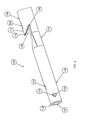
- Figs. 4, 5, and 6 show an enlarged perspective view, an enlarged.top plan view and an enlarged side view, respectively, of the distal end 104 of the catheter assembly 100.
- a transition portion 119 of the first lumen 110 disposed between the first distal tip and the second distal tip transitions the cross-section of the first lumen 110 from the D-shape shown in Fig. 2 to the generally circular cross section shape shown in Fig. 3.
- the body 108 is constructed from a polymer or elastomer, such as carbothane, with an approximately 20% barium sulfat/pellethane composition to aid in locating the body 108 within the patient's vessel after insertion, such as by ultrasound and fluoroscopy.
- a polymer or elastomer such as carbothane
- barium sulfat/pellethane composition to aid in locating the body 108 within the patient's vessel after insertion, such as by ultrasound and fluoroscopy.
- the body 108 has a hardness of approximately 80-A on the Shore durometer scale, although those skilled in the art will recognize that the body 108 may be harder or softer.
- a catheter tissue ingrowth cuff 124 is disposed along an exterior of the body 108 between the second distal tip 116 and the hub 106.
- the catheter tissue ingrowth cuff 124 is used for chronic catheter insertions, wherein the catheter assembly 100 is intended to be inserted into the patient for extended periods of time, such as for several months.
- the catheter tissue ingrowth cuff 124 is disposed within a subcutaneous tunnel according to methods known by those skilled in the art.
- the catheter tissue ingrowth cuff 124 is constructed from a generally coarse fabric material, such as a polyester or DACRON®, to enable ingrowing subcutaneous/skin tissue to engage the material and secure the catheter ingrowth cuff 124 to the subcutaneous/skin tissue.
- the catheter assembly 100 need not be subcutaneously tunnelled, and the catheter ingrowth cuff 124 may be omitted.
- the proximal end 102 of the catheter assembly 100 includes a first extension tube 130 that fluidly communicates with the first lumen 110 at a distal end 132 of the first extension tube through a first hub conduit 133.
- the first hub conduit 133 transitions from a generally circular cross section at the first extension tube 130 to a generally D-shaped cross section at the first lumen 110.
- the proximal end 102 of the catheter assembly 100 also includes a second extension tube 140 that fluidly communicates with the second lumen 112 at a distal end 142 of the second extension tube 140 through a second hub conduit 143.
- the second hub conduit 143 transitions from a generally circular cross section at the second extension tube 140 to a generally D-shaped cross section at the second lumen 112.
- a first clamp 138 such as a Roberts clamp is preferably disposed over the first extension tube 130 between the proximal end 134 and the distal end 132 of the first extension tube 130
- a second clamp 148 is preferably disposed over the second extension tube 140 between the proximal end 144 and the distal end 142 of the second extension tube 140.
- the first and second clamps 138,148 serve to releasably secure each of the first and second extension tubes 130,140, respectively, preventing fluid flow through each of the first and second extension tubes 130, 140 when the respective clamp 138,148 is in the closed position.
- the first lumen 110 preferably includes at least one and, more preferably, a plurality of first side ports 154, each being disposed in a plane generally perpendicular to the plane of the sidewall 118.
- each of the plurality of first side ports 154 is generally circular, although those skilled in the art will recognize that the first side ports 154 may be other shapes.
- the first distal tip 114 includes a generally circular bevel to facilitate a smooth transition between the first distal tip 114 and the body of the first lumen 110, and to reduce the risk of the first distal tip 114 snagging the wall of the blood vessel during insertion.
- the second distal tip 116 of the second lumen 112 is generally parabolic in shape and extends obliquely away from the sidewall 118 distally toward the first distal opening 151.
- the generally parabolic shape of the second distal tip 116 forms an overhanging lip, as seen in Figs. 1, 4, and 6.
- the second distal tip 116 of the second lumen 112 extends at an angle ⁇ 1 of approximately 37.5 degrees relative to the plane of the sidewall 118, although those skilled in the art will recognize that the angle ⁇ 1 may be other than 37.5 degrees.
- the second distal tip 116 preferably includes a second distal opening 155 and a second guide wire opening 156 that is disposed proximally of the second distal opening 155.
- the second guide wire opening 156 is generally oblong or oval in shape, with a major axis of the second guide wire opening 156 extending parallel to a major axis of the body 108.
- the transition portion 119 preferably includes a tapered wall 158 that angles at an angle 82 of approximately 30 degrees from the plane of the sidewall 118.
- a cavity 160 is formed between the tapered wall 158 and the second distal tip 116. The cavity 160 and the oblique shape of the second distal tip 116 assist in blood flow into the second lumen 112 through the second distal tip opening 155 during hemodialysis, as will be described in more detail later herein.
- the catheter assembly 100 is inserted over the guide wire. This insertion technique eliminates the need for a sheath to be inserted over the guide wire, greatly reducing the risk of air embolism.
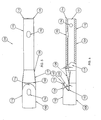
- the proximal end 162 of the guide wire 160 is next pulled longitudinally along the exterior of the first lumen 110 and over the second distal tip 116 to the second guide wire opening 156, where the proximal end 162 of the guide wire 160 is inserted through the second guide wire opening 156 and into the second lumen 112.
- the proximal end 162 of the guide wire 160 is inserted through the second lumen 112 and pushed through the second lumen 112 until the proximal end 162 of the guide wire 160 exits the catheter assembly 100.
- the guide wire 160 As the guide wire 160 is pulled through both the first guide wire opening 152 and the second guide wire opening 156, the guide wire 160 between the first guide wire opening 152 and the second guide wire opening 156 engages the second distal tip 116 and directs the second distal tip 116 into the cavity 160, as shown in Fig. 7. With the second distal tip 116 in this position, the distal end 104 of the catheter assembly 100 may be inserted into the vessel more directly, preventing the second distal tip 116 from catching on the wall of the blood vessel and potentially snagging on the wall of the vessel. The distal end 104 of the catheter assembly 100 is inserted as far into the vessel as desired by the physician, and as confirmed by fluoroscopy.
- first and second connectors 136, 146 are connected in fluid communication to respective fluid inlets and outlets of a hemodialysis unit (not shown), or other fluid transfer equipment (not shown) and dialysis may now begin.
- the blood drawn into the second lumen 112 flows to the hemodialysis machine where the blood is cleaned and processed.
- the blood is then pumped through the first lumen 110 for discharge back into the vessel.
- the first distal opening 151 and the first side ports 154 provide discharge ports for the blood to be discharged from the first lumen 110.
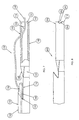
- a distal end 204 of an alternate embodiment of a catheter assembly 200 having an alternate first distal tip 214 is shown in Fig. 8.
- the alternate first distal tip 214 includes a plurality of side ports 254 that are each generally semi-circular and end at the most distal portion of the first distal tip 214, merging with the first distal opening 251.
Landscapes
- Health & Medical Sciences (AREA)
- Life Sciences & Earth Sciences (AREA)
- Biophysics (AREA)
- Pulmonology (AREA)
- Engineering & Computer Science (AREA)
- Anesthesiology (AREA)
- Biomedical Technology (AREA)
- Heart & Thoracic Surgery (AREA)
- Hematology (AREA)
- Animal Behavior & Ethology (AREA)
- General Health & Medical Sciences (AREA)
- Public Health (AREA)
- Veterinary Medicine (AREA)
- Media Introduction/Drainage Providing Device (AREA)
- Materials For Medical Uses (AREA)
- Surgical Instruments (AREA)
Abstract
Description
- The present invention relates to a multilumen catheter assembly used to simultaneously withdraw and infuse a fluid to a body, such as during hemodialysis.
- Catheters for the introduction or removal of fluids may be placed in various venous locations and cavities throughout the body for introduction or removal of these fluids. Such catheterization may be performed by using a single catheter assembly having multiple lumens. A typical example of a multiple lumen catheter assembly is a dual lumen catheter in which one lumen introduces fluid and the other lumen removes fluid. Such a multiple lumen catheter assembly is known as the SPLIT STREAM™ catheter, manufactured and sold by Medical Components, Inc. of Harleysville, Pennsylvania.
- Generally, to insert any catheter into a blood vessel, the vessel is identified by aspiration through a long hollow needle in accordance with the well known Seldinger technique. When blood enters a syringe attached to the needle, indicating that the vessel has been found, a thin guide wire is then introduced, typically through the puncturing needle or other introducer device into the lumen of the vessel. The introducer device is then removed, leaving the guide wire within the vessel. The guide wire projects beyond the surface of the skin. At this point, several options are available to a physician for catheter placement. The simplest is to pass a catheter into the vessel directly over the guide wire. The guide wire is then removed, leaving the catheter in position within the vessel. However, this technique is only possible in cases where the catheter is of a relatively small diameter, made of a stiff material, and not significantly larger than the guide wire, for example, for insertion of small diameter dual lumen catheters. If the catheter to be inserted is significantly larger than the guide wire, a dilator device is passed over the guide wire to enlarge the opening into the vessel and then removed. The catheter is then passed over the guide wire, and the guide wire is then removed, leaving the catheter within the vessel.
- During hemodialysis, the two lumens, the arterial lumen and the venous lumen, are connected to a hemodialysis machine and are used to remove toxic blood from the patient for dialysis and to return dialyzed blood to the patient, respectively. However, suction of the toxic blood into the arterial lumen may draw the distal opening of the arterial lumen against the wall of the blood vessel into which the lumen is inserted, reducing or cutting off blood flow through the arterial lumen, and significantly reducing the amount of blood being dialyzed. This reduction in blood flow can lead to longer dialysis period, or result in less dialysis of the patient's blood. It would be beneficial to provide a catheter that reduces the suction of the arterial lumen against the blood vessel wall.
- US 5,405,341 discloses a catheter assembly having an elongated main body extending longitudinally between proximal and distal ends, wherein a longitudinally extendable tip structure is attached to the distal end.
- Twardowski et al., U.S. Patent No. 5,405,320 and Davey et al., U.S. Patent No. 6,280,423 B1 both disclose dual lumen catheters with an arterial lumen that includes an overhanging lip or shield to reduce the suction of the arterial lumen against the blood vessel wall. However, neither Twardowski et al. nor Davey et al. disclose a structure or method for inserting the catheter into the blood vessel that minimizes the likelihood of the overhanging lip from snagging on the blood vessel wall during insertion. It would be beneficial to provide a catheter having an overhanging lip and a method of inserting the catheter that minimizes the likelihood of such snagging.
- Briefly, the present invention provides a multilumen catheter assembly. The assembly includes an elongated tubular body, divided by a sidewall extending throughout the center of the tube, dividing the tube into two generally "D-shaped" lumens, of which the distal openings are at unequal lengths. The most distal tip is round and non-tapered with an oval side opening just proximal to the distal opening to facilitate guide wire passage. The shorter, more proximal undercut lip lumen has a single oval side hole opening directly centered just proximal to the center of the undercut (overhanging) lip. The two oval side holes facilitate passage of a guide wire for insertion. The shorter lumen (the arterial or aspiration port) connects through a connecting hub assembly to allow oblique connection of an arterial (generally red color coded) port her-lock connection tube. The longer lumen (the venous or return port) connects in the hub assembly in a straight-through direction for connection to the venous (generally blue color coded) luer-lock connection tube.
- Additionally, the present invention provides a method of inserting a catheter assembly over a catheter guide wire. The guide wire is inserted from the tip of the longer (venous return) lumen, out the oval guide wire side hole parallel to the lumen and enters the shorter (arterial aspiration) lumen through the oval guide wire hole into the lumen of the aspiration port. The guide wire is then advanced through the length of the catheter to exit the red luer-lock connector. The catheter is then advanced over the guide wire for percutaneous insertion without a peel away sheath, thus minimizing the possibility of bleeding and air embolism. The course of the guide wire through the catheter tips allows an insertion course co-axial to the guide wire and provides that the overhanging undercut lip of the shorter port is folded down against the longer venous port to prevent difficult Passage as the catheter passes through the venatory site.
- The accompanying drawings, which are incorporated herein and constitute part of this specification, illustrate the presently preferred embodiments of the invention, and, together with the general description given above and the detailed description given below, serve to explain the features of the invention. In the drawings:
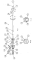
- Fig. 1 is a side view of a catheter assembly according to a preferred embodiment of the present invention.
- Fig. 2 is an enlarged cross sectional view of the catheter lumens shown in Fig. 1, taken along lines 2-2 of Fig. 1.
- Fig. 3 is an enlarged cross sectional view of the catheter lumens shown in Fig. 1, taken along lines 3-3 of Fig. 1.
- Fig. 4 is an enlarged perspective view of a distal end of the catheter assembly shown in Fig.1.
- Fig. 5 is an enlarged top plan view of the distal end of the catheter assembly shown in Fig. 1.
- Fig. 6 is an enlarged side view of the distal end of the catheter assembly shown in Fig. 1.
- Fig. 7 is an enlarged side view of the distal end of the catheter assembly shown in Fig. 1, with a guide wire strung through the distal end of the catheter assembly as during insertion of the catheter assembly.
- Fig. 8 is an enlarged side view of a distal end of an alternate embodiment of a catheter assembly according to an alternative embodiment of the present invention.
- In the drawings, like numerals indicate like elements throughout. Certain terminology is used herein for convenience only and is not to be taken as a limitation on the present invention. The words "proximal" and "distal" refer to directions away from and closer to, respectively, the insertion tip of the catheter according to the present invention. The terminology includes the words above specifically mentioned, derivatives thereof, and words of similar import. The following describes preferred embodiments of the invention. However, it should be understood based on this disclosure, that the invention is not limited by the preferred embodiments described herein.
- Referring now to Fig. 1, a side view of a
catheter assembly 100 according to a preferred embodiment of the present invention is shown. Thecatheter assembly 100 includes aproximal end 102, adistal end 104, and ahub 106 connecting theproximal end 102 and thedistal end 104. Anelongated body 108 extends between thehub 106 and thedistal end 104. Theelongated body 108 is preferably comprised of afirst catheter lumen 110, also shown as a venous lumen and asecond catheter lumen 112, also known as an arterial lumen. While only two catheter lumens 110,112 are shown, those skilled in the art will recognize that thecatheter assembly 100 may include more than two lumens 110,112. - The
first lumen 110 extends all of the way between thehub 106 and thedistal end 104 and terminates at thedistal end 104 in a firstdistal tip 114, while thesecond lumen 112 begins at thehub 106, but terminates prior to thedistal end 104 at a seconddistal tip 116. Fig. 2 shows an enlarged sectional view of the first andsecond lumens distal tip 116. Acommon sidewall 118 extends from thehub 106 and terminates at the seconddistal tip 116. Fig. 3 shows an enlarged sectional view of thefirst lumen 110 distal of the seconddistal tip 116. - Referring back to Fig. 2, the
catheter body 108 preferably has a generally circular cross section, with thefirst lumen 110 and thesecond lumen 112 each having a generally "D-shaped" cross section, juxtaposed from each other across thecommon sidewall 118. Although the cross section of thebody 108 is preferably circular, those skilled in the art will recognize that the cross section of thebody 108 may be other shapes, such as oval. It is preferred that the cross section of thebody 108 be a generally smooth curve to facilitate sealing of the patient's skin around thebody 108 at the incision site, as well as at the entrance to the vessel, to minimize bleeding. Distal of the seconddistal tip 116, thefirst lumen 110 preferably has a generally circular cross section. - Figs. 4, 5, and 6 show an enlarged perspective view, an enlarged.top plan view and an enlarged side view, respectively, of the
distal end 104 of thecatheter assembly 100. Atransition portion 119 of thefirst lumen 110 disposed between the first distal tip and the second distal tip transitions the cross-section of thefirst lumen 110 from the D-shape shown in Fig. 2 to the generally circular cross section shape shown in Fig. 3. - Preferably, the
body 108 is constructed from a polymer or elastomer, such as carbothane, with an approximately 20% barium sulfat/pellethane composition to aid in locating thebody 108 within the patient's vessel after insertion, such as by ultrasound and fluoroscopy. However, those skilled in the art will recognize that other biocompatible materials may be used for thebody 108. Preferably, thebody 108 has a hardness of approximately 80-A on the Shore durometer scale, although those skilled in the art will recognize that thebody 108 may be harder or softer. - Referring back to Fig. 1, the
hub 106 preferably includes asuture wing 120 that extends generally transverse of thebody 108. Thesuture wing 120 preferably includes at least one and, more preferably, at least twosuture openings 122 that allow an inserting physician to suture thehub 106 to the external skin of the patient into whom the physician has inserted thecatheter assembly 100 to prevent thecatheter assembly 100 from being dislodged from its inserted position within the patient. Thesuture wing 120 may be fixedly connected to thehub 106, or thesuture wing 120 may be rotatably connected to thehub 106, to allow thesuture wing 120 to rotate about thehub 106, allowing the inserting physician additional flexibility in positioning thehub 106 relative to the skin of the patient - Preferably, a catheter
tissue ingrowth cuff 124 is disposed along an exterior of thebody 108 between the seconddistal tip 116 and thehub 106. The cathetertissue ingrowth cuff 124 is used for chronic catheter insertions, wherein thecatheter assembly 100 is intended to be inserted into the patient for extended periods of time, such as for several months. The cathetertissue ingrowth cuff 124 is disposed within a subcutaneous tunnel according to methods known by those skilled in the art. Preferably, the cathetertissue ingrowth cuff 124 is constructed from a generally coarse fabric material, such as a polyester or DACRON®, to enable ingrowing subcutaneous/skin tissue to engage the material and secure thecatheter ingrowth cuff 124 to the subcutaneous/skin tissue. For an acute catheterization, thecatheter assembly 100 need not be subcutaneously tunnelled, and thecatheter ingrowth cuff 124 may be omitted. - The
proximal end 102 of thecatheter assembly 100 includes afirst extension tube 130 that fluidly communicates with thefirst lumen 110 at adistal end 132 of the first extension tube through afirst hub conduit 133. Thefirst hub conduit 133 transitions from a generally circular cross section at thefirst extension tube 130 to a generally D-shaped cross section at thefirst lumen 110. Theproximal end 102 of thecatheter assembly 100 also includes asecond extension tube 140 that fluidly communicates with thesecond lumen 112 at adistal end 142 of thesecond extension tube 140 through asecond hub conduit 143. Thesecond hub conduit 143 transitions from a generally circular cross section at thesecond extension tube 140 to a generally D-shaped cross section at thesecond lumen 112. Preferably, thefirst extension tube 130 extends generally co-axially with thefirst lumen 110 and thesecond extension tube 140 extends at an angle of approximately 20 degrees relative to the length of thesecond lumen 112, although those skilled in the art will recognize that the first andsecond extension tubes second extension tubes proximal end 134 of thefirst extension tube 130 preferably terminates at afirst collector 136, such as a Standard her lock, as is well known in the art. Preferably, thefirst connector 136 is color coded blue to indicate connection to thevenous lumen 110. Also, aproximal end 144 of thesecond extension tube 140 preferably terminates at asecond connector 146, such as a standard luer lock. Preferably, thesecond connector 146 is color coded red to indicate connection to thearterial lumen 112. - A
first clamp 138, such as a Roberts clamp is preferably disposed over thefirst extension tube 130 between theproximal end 134 and thedistal end 132 of thefirst extension tube 130, and asecond clamp 148 is preferably disposed over thesecond extension tube 140 between theproximal end 144 and thedistal end 142 of thesecond extension tube 140. The first and second clamps 138,148 serve to releasably secure each of the first and second extension tubes 130,140, respectively, preventing fluid flow through each of the first andsecond extension tubes - An
information ring respective clamp information ring - Referring back to Figs. 4-6, the
distal end 104 of thecatheter assembly 100 is now described in more detail. Thefirst lumen 110 preferably includes a generally circular firstdistal opening 151 disposed at the firstdistal tip 114 and a firstguide wire opening 152 that is disposed proximally of the firstdistal tip 114. Preferably, the firstguide wire opening 152 is generally oblong or oval in shape, with a major axis of the firstguide wire opening 152 extending parallel to a major axis of thebody 108. The firstguide wire opening 152 is preferably generally parallel to a plane of thesidewall 118. Further, thefirst lumen 110 preferably includes at least one and, more preferably, a plurality offirst side ports 154, each being disposed in a plane generally perpendicular to the plane of thesidewall 118. Preferably, each of the plurality offirst side ports 154 is generally circular, although those skilled in the art will recognize that thefirst side ports 154 may be other shapes. Preferably, the firstdistal tip 114 includes a generally circular bevel to facilitate a smooth transition between the firstdistal tip 114 and the body of thefirst lumen 110, and to reduce the risk of the firstdistal tip 114 snagging the wall of the blood vessel during insertion. - The second
distal tip 116 of thesecond lumen 112 is generally parabolic in shape and extends obliquely away from thesidewall 118 distally toward the firstdistal opening 151. The generally parabolic shape of the seconddistal tip 116 forms an overhanging lip, as seen in Figs. 1, 4, and 6. Referring to Fig. 6 only, preferably, the seconddistal tip 116 of thesecond lumen 112 extends at an angle β1 of approximately 37.5 degrees relative to the plane of thesidewall 118, although those skilled in the art will recognize that the angle β1 may be other than 37.5 degrees. - Referring to Figs. 4 and 6, the second
distal tip 116 preferably includes a seconddistal opening 155 and a secondguide wire opening 156 that is disposed proximally of the seconddistal opening 155. Preferably, the secondguide wire opening 156 is generally oblong or oval in shape, with a major axis of the secondguide wire opening 156 extending parallel to a major axis of thebody 108. - The
transition portion 119 preferably includes atapered wall 158 that angles at an angle 82 of approximately 30 degrees from the plane of thesidewall 118. Acavity 160 is formed between thetapered wall 158 and the seconddistal tip 116. Thecavity 160 and the oblique shape of the seconddistal tip 116 assist in blood flow into thesecond lumen 112 through the second distal tip opening 155 during hemodialysis, as will be described in more detail later herein. - To insert the
catheter assembly 100 into the patient, an incision is initially made near an insertion site on the patient's skin, which is to be aspirated with a syringe or other introducer apparatus near or proximate the area to be catheterized. If thecatheter assembly 100 is used for hemodialysis and the area to be catheterized is the internal jugular vein, the incision is made in the clavicular triangle region. The exact location of the incision can be varied by the physician. In accordance with the Seldinger technique, a hollow needle is inserted through the incision and into the vein, and the vein is then aspirated. A guide wire is then passed through the needle and the needle is removed. Next, after dilating the soft tissue h c k and venatory site, thecatheter assembly 100 is inserted over the guide wire. This insertion technique eliminates the need for a sheath to be inserted over the guide wire, greatly reducing the risk of air embolism. - Prior to insertion of the
catheter assembly 100 into the patient, thecatheter assembly 100 of Fig. 1 is inserted over the proximal end of the guide wire as follows. Aproximal end 162 of aguide wire 160, shown in Fig. 7, is inserted into the firstdistal opening 151 and pushed through thefirst lumen 110 to the firstguide wire opening 152. Theproximal end 162 of theguide wire 160 is then pushed through the firstguide wire opening 152, so that theproximal end 162 of theguide wire 160 exits thecatheter body 108. Theproximal end 162 of theguide wire 160 is next pulled longitudinally along the exterior of thefirst lumen 110 and over the seconddistal tip 116 to the secondguide wire opening 156, where theproximal end 162 of theguide wire 160 is inserted through the secondguide wire opening 156 and into thesecond lumen 112. Theproximal end 162 of theguide wire 160 is inserted through thesecond lumen 112 and pushed through thesecond lumen 112 until theproximal end 162 of theguide wire 160 exits thecatheter assembly 100. - As the
guide wire 160 is pulled through both the firstguide wire opening 152 and the secondguide wire opening 156, theguide wire 160 between the firstguide wire opening 152 and the secondguide wire opening 156 engages the seconddistal tip 116 and directs the seconddistal tip 116 into thecavity 160, as shown in Fig. 7. With the seconddistal tip 116 in this position, thedistal end 104 of thecatheter assembly 100 may be inserted into the vessel more directly, preventing the seconddistal tip 116 from catching on the wall of the blood vessel and potentially snagging on the wall of the vessel. Thedistal end 104 of thecatheter assembly 100 is inserted as far into the vessel as desired by the physician, and as confirmed by fluoroscopy. When thedistal end 104 of thecatheter 100 is in its desired position, theguide wire 160 is pulled through theproximal end 102 of thecatheter assembly 100 and removed. Next, the incision is closed and thehub 106 is secured to the external skin of the Patient by suturing thesuture wing 120 to the skin. The open ends of first andsecond connectors - In use, after the dialysis machine is connected to the
catheter assembly 100 and turned on, the dialysis machine draws blood from the vessel through thesecond lumen 112. In the event that the pressure drop in the vessel caused by the blood being drawn into thesecond lumen 112 forces the wall of the vessel toward the seconddistal opening 155, the overhanging lip of the seconddistal tip 116 prevents the vessel wall from totally occluding the seconddistal opening 155 and shutting off blood flow through thesecond lumen 112. - The blood drawn into the
second lumen 112 flows to the hemodialysis machine where the blood is cleaned and processed. The blood is then pumped through thefirst lumen 110 for discharge back into the vessel. The firstdistal opening 151 and thefirst side ports 154 provide discharge ports for the blood to be discharged from thefirst lumen 110. - A
distal end 204 of an alternate embodiment of acatheter assembly 200 having an alternate firstdistal tip 214 is shown in Fig. 8. Instead of a plurality of generallycircular side ports 154 as shown in the firstdistal tip 114 of the embodiment in Fig. 4, the alternate firstdistal tip 214 includes a plurality ofside ports 254 that are each generally semi-circular and end at the most distal portion of the firstdistal tip 214, merging with the firstdistal opening 251.
Claims (11)
- A multilumen catheter assembly (100, 200) comprising an elongated body (108) having a proximal end (102) and a distal end (104, 204), a first lumen (110) having a sidewall (118) extending between the proximal end (102) and the distal end (104, 204), a first distal opening (151, 251) disposed at the distal end (104,204), a first guide wire opening (152) disposed proximally of the distal end (104, 204) and co-planar with the sidewall (118) and a second lumen (112) connected to the sidewall (118) and extending between the proximal end (102) and a second distal end (116) proximal of the distal end (104,204), wherein the second lumen (112) includes a second opening (155) extending obliquely away from the sidewall (118) distally toward the first opening (151)
characterized by
a second guide wire opening (156) disposed proximally of the second opening (155) and in a plane generally parallel to the sidewall (118). - The multilumen catheter assembly (100, 200) according to claim 1, further comprising a hub (106) connected to the proximal end (102) of the body (108).
- The multilumen catheter assembly (100, 200) according to claim 1, wherein the first lumen (110) further comprises at least one opening (154, 254) disposed proximate of the distal end (104,204).
- The multilumen catheter assembly (100, 200) according to claim 1, wherein the first distal opening (104, 204) is disposed in a plane generally perpendicular to a plane of the sidewall (118).
- The multilumen catheter assembly (100, 200) according to claim 1, wherein the first distal opening (104, 204) is generally circular.
- The multilumen catheter assembly (100, 200) according to claim 1, wherein the first lumen (110) has a generally D-shaped cross section proximate of the second opening (155).
- The multilumen catheter assembly (100, 200) according to claim 1, wherein the second lumen (112) has a generally D-shaped cross section.
- The multilumen catheter assembly (100, 200) according to claim 1, wherein the body (108) has a generally round cross-section.
- The multilumen catheter assembly (100, 200) according to claim 1, wherein the second opening (155) is tapered.
- The multilumen catheter assembly (100, 200) according to claim 1, wherein the first guide wire opening (152) is generally oval shaped.
- The multilumen catheter assembly (100, 200) according to claim 1, wherein the second guide wire opening (156) is generally oval shaped.
Applications Claiming Priority (3)
| Application Number | Priority Date | Filing Date | Title |
|---|---|---|---|
| US40593702P | 2002-08-23 | 2002-08-23 | |
| US405937P | 2002-08-23 | ||
| PCT/US2003/026163 WO2004018016A2 (en) | 2002-08-23 | 2003-08-21 | Shielded tip catheter |
Publications (3)
| Publication Number | Publication Date |
|---|---|
| EP1534372A2 EP1534372A2 (en) | 2005-06-01 |
| EP1534372A4 EP1534372A4 (en) | 2005-08-17 |
| EP1534372B1 true EP1534372B1 (en) | 2006-07-05 |
Family
ID=31946947
Family Applications (1)
| Application Number | Title | Priority Date | Filing Date |
|---|---|---|---|
| EP03793206A Expired - Lifetime EP1534372B1 (en) | 2002-08-23 | 2003-08-21 | Shielded tip catheter |
Country Status (6)
| Country | Link |
|---|---|
| EP (1) | EP1534372B1 (en) |
| AT (1) | ATE332163T1 (en) |
| AU (1) | AU2003258317A1 (en) |
| CA (1) | CA2495687C (en) |
| DE (1) | DE60306659T2 (en) |
| WO (1) | WO2004018016A2 (en) |
Families Citing this family (1)
| Publication number | Priority date | Publication date | Assignee | Title |
|---|---|---|---|---|
| JP2009511199A (en) * | 2005-10-11 | 2009-03-19 | フロウメディカ, インコーポレイテッド | Vascular sheath with variable lumen configuration |
Family Cites Families (6)
| Publication number | Priority date | Publication date | Assignee | Title |
|---|---|---|---|---|
| US5273042A (en) * | 1987-10-28 | 1993-12-28 | Medical Parameters, Inc. | Guidewire advancement method |
| CA1330285C (en) * | 1987-12-22 | 1994-06-21 | Geoffrey S. Martin | Triple lumen catheter |
| US5312328A (en) * | 1991-01-11 | 1994-05-17 | Baxter International Inc. | Ultra-sound catheter for removing obstructions from tubular anatomical structures such as blood vessels |
| US5405341A (en) * | 1993-06-03 | 1995-04-11 | Med-Pro Design, Inc. | Catheter with multiple lumens |
| US6117153A (en) * | 1996-10-03 | 2000-09-12 | Interventional Technologies, Inc. | Neovascularization catheter |
| JP4612186B2 (en) * | 1998-02-24 | 2011-01-12 | ナビリスト メディカル, インコーポレイテッド | High flow dialysis catheter and related methods |
-
2003
- 2003-08-21 EP EP03793206A patent/EP1534372B1/en not_active Expired - Lifetime
- 2003-08-21 DE DE60306659T patent/DE60306659T2/en not_active Expired - Lifetime
- 2003-08-21 AU AU2003258317A patent/AU2003258317A1/en not_active Abandoned
- 2003-08-21 AT AT03793206T patent/ATE332163T1/en not_active IP Right Cessation
- 2003-08-21 CA CA002495687A patent/CA2495687C/en not_active Expired - Lifetime
- 2003-08-21 WO PCT/US2003/026163 patent/WO2004018016A2/en not_active Ceased
Also Published As
| Publication number | Publication date |
|---|---|
| DE60306659D1 (en) | 2006-08-17 |
| CA2495687A1 (en) | 2004-03-04 |
| WO2004018016A2 (en) | 2004-03-04 |
| CA2495687C (en) | 2008-05-20 |
| ATE332163T1 (en) | 2006-07-15 |
| DE60306659T2 (en) | 2007-06-28 |
| WO2004018016A3 (en) | 2005-01-13 |
| AU2003258317A1 (en) | 2004-03-11 |
| EP1534372A4 (en) | 2005-08-17 |
| EP1534372A2 (en) | 2005-06-01 |
| AU2003258317A8 (en) | 2004-03-11 |
Similar Documents
| Publication | Publication Date | Title |
|---|---|---|
| US7066925B2 (en) | Method of using a shielded tip catheter | |
| US7011645B2 (en) | Dialysis catheter | |
| EP1225934B1 (en) | Bolus tip design for a multi-lumen catheter | |
| US20040176739A1 (en) | Catheter tunneler and adapter | |
| US7077829B2 (en) | Dialysis catheter | |
| JP4372518B2 (en) | Blood treatment catheter assembly | |
| CN101909672B (en) | Split-tip catheter including lateral distal openings | |
| US8905998B2 (en) | Catheter tunneler adapter and methods of assembly to a catheter and use | |
| EP1432462B1 (en) | Catheter | |
| US7074213B2 (en) | Dialysis catheter | |
| US6682498B2 (en) | Methods and systems for subcutaneous graft implantation | |
| US7575563B2 (en) | Blood treatment catheter assembly | |
| US20040097903A1 (en) | Removable catheter hub | |
| EP1694377B1 (en) | Catheter button hub | |
| JP2012228531A (en) | Combination of introducer sheath with catheter | |
| EP1534372B1 (en) | Shielded tip catheter | |
| US8708956B2 (en) | Multi-lumen catheter with protected tip | |
| WO2007145796A2 (en) | Multi-lumen catheter with protected tip | |
| JP2007007042A (en) | Multi-guide hole catheter, multi-guide hole catheter assembly , and method for operating the assembly | |
| EP1556112A1 (en) | Dialysis catheter |
Legal Events
| Date | Code | Title | Description |
|---|---|---|---|
| PUAI | Public reference made under article 153(3) epc to a published international application that has entered the european phase |
Free format text: ORIGINAL CODE: 0009012 |
|
| 17P | Request for examination filed |
Effective date: 20050311 |
|
| AK | Designated contracting states |
Kind code of ref document: A2 Designated state(s): AT BE BG CH CY CZ DE DK EE ES FI FR GB GR HU IE IT LI LU MC NL PT RO SE SI SK TR |
|
| AX | Request for extension of the european patent |
Extension state: AL LT LV MK |
|
| A4 | Supplementary search report drawn up and despatched |
Effective date: 20050704 |
|
| DAX | Request for extension of the european patent (deleted) | ||
| GRAP | Despatch of communication of intention to grant a patent |
Free format text: ORIGINAL CODE: EPIDOSNIGR1 |
|
| GRAS | Grant fee paid |
Free format text: ORIGINAL CODE: EPIDOSNIGR3 |
|
| GRAA | (expected) grant |
Free format text: ORIGINAL CODE: 0009210 |
|
| AK | Designated contracting states |
Kind code of ref document: B1 Designated state(s): AT BE BG CH CY CZ DE DK EE ES FI FR GB GR HU IE IT LI LU MC NL PT RO SE SI SK TR |
|
| PG25 | Lapsed in a contracting state [announced via postgrant information from national office to epo] |
Ref country code: SI Free format text: LAPSE BECAUSE OF FAILURE TO SUBMIT A TRANSLATION OF THE DESCRIPTION OR TO PAY THE FEE WITHIN THE PRESCRIBED TIME-LIMIT Effective date: 20060705 Ref country code: LI Free format text: LAPSE BECAUSE OF FAILURE TO SUBMIT A TRANSLATION OF THE DESCRIPTION OR TO PAY THE FEE WITHIN THE PRESCRIBED TIME-LIMIT Effective date: 20060705 Ref country code: IT Free format text: LAPSE BECAUSE OF FAILURE TO SUBMIT A TRANSLATION OF THE DESCRIPTION OR TO PAY THE FEE WITHIN THE PRESCRIBED TIME-LIMIT;WARNING: LAPSES OF ITALIAN PATENTS WITH EFFECTIVE DATE BEFORE 2007 MAY HAVE OCCURRED AT ANY TIME BEFORE 2007. THE CORRECT EFFECTIVE DATE MAY BE DIFFERENT FROM THE ONE RECORDED. Effective date: 20060705 Ref country code: SK Free format text: LAPSE BECAUSE OF FAILURE TO SUBMIT A TRANSLATION OF THE DESCRIPTION OR TO PAY THE FEE WITHIN THE PRESCRIBED TIME-LIMIT Effective date: 20060705 Ref country code: AT Free format text: LAPSE BECAUSE OF FAILURE TO SUBMIT A TRANSLATION OF THE DESCRIPTION OR TO PAY THE FEE WITHIN THE PRESCRIBED TIME-LIMIT Effective date: 20060705 Ref country code: BE Free format text: LAPSE BECAUSE OF FAILURE TO SUBMIT A TRANSLATION OF THE DESCRIPTION OR TO PAY THE FEE WITHIN THE PRESCRIBED TIME-LIMIT Effective date: 20060705 Ref country code: CH Free format text: LAPSE BECAUSE OF FAILURE TO SUBMIT A TRANSLATION OF THE DESCRIPTION OR TO PAY THE FEE WITHIN THE PRESCRIBED TIME-LIMIT Effective date: 20060705 Ref country code: CZ Free format text: LAPSE BECAUSE OF FAILURE TO SUBMIT A TRANSLATION OF THE DESCRIPTION OR TO PAY THE FEE WITHIN THE PRESCRIBED TIME-LIMIT Effective date: 20060705 Ref country code: NL Free format text: LAPSE BECAUSE OF FAILURE TO SUBMIT A TRANSLATION OF THE DESCRIPTION OR TO PAY THE FEE WITHIN THE PRESCRIBED TIME-LIMIT Effective date: 20060705 Ref country code: RO Free format text: LAPSE BECAUSE OF FAILURE TO SUBMIT A TRANSLATION OF THE DESCRIPTION OR TO PAY THE FEE WITHIN THE PRESCRIBED TIME-LIMIT Effective date: 20060705 Ref country code: FI Free format text: LAPSE BECAUSE OF FAILURE TO SUBMIT A TRANSLATION OF THE DESCRIPTION OR TO PAY THE FEE WITHIN THE PRESCRIBED TIME-LIMIT Effective date: 20060705 |
|
| REG | Reference to a national code |
Ref country code: GB Ref legal event code: FG4D |
|
| REG | Reference to a national code |
Ref country code: CH Ref legal event code: EP |
|
| REG | Reference to a national code |
Ref country code: IE Ref legal event code: FG4D |
|
| REF | Corresponds to: |
Ref document number: 60306659 Country of ref document: DE Date of ref document: 20060817 Kind code of ref document: P |
|
| PG25 | Lapsed in a contracting state [announced via postgrant information from national office to epo] |
Ref country code: MC Free format text: LAPSE BECAUSE OF NON-PAYMENT OF DUE FEES Effective date: 20060831 |
|
| PG25 | Lapsed in a contracting state [announced via postgrant information from national office to epo] |
Ref country code: DK Free format text: LAPSE BECAUSE OF FAILURE TO SUBMIT A TRANSLATION OF THE DESCRIPTION OR TO PAY THE FEE WITHIN THE PRESCRIBED TIME-LIMIT Effective date: 20061005 Ref country code: BG Free format text: LAPSE BECAUSE OF FAILURE TO SUBMIT A TRANSLATION OF THE DESCRIPTION OR TO PAY THE FEE WITHIN THE PRESCRIBED TIME-LIMIT Effective date: 20061005 Ref country code: SE Free format text: LAPSE BECAUSE OF FAILURE TO SUBMIT A TRANSLATION OF THE DESCRIPTION OR TO PAY THE FEE WITHIN THE PRESCRIBED TIME-LIMIT Effective date: 20061005 |
|
| PG25 | Lapsed in a contracting state [announced via postgrant information from national office to epo] |
Ref country code: ES Free format text: LAPSE BECAUSE OF FAILURE TO SUBMIT A TRANSLATION OF THE DESCRIPTION OR TO PAY THE FEE WITHIN THE PRESCRIBED TIME-LIMIT Effective date: 20061016 |
|
| NLV1 | Nl: lapsed or annulled due to failure to fulfill the requirements of art. 29p and 29m of the patents act | ||
| PG25 | Lapsed in a contracting state [announced via postgrant information from national office to epo] |
Ref country code: PT Free format text: LAPSE BECAUSE OF FAILURE TO SUBMIT A TRANSLATION OF THE DESCRIPTION OR TO PAY THE FEE WITHIN THE PRESCRIBED TIME-LIMIT Effective date: 20061205 |
|
| ET | Fr: translation filed | ||
| PLBE | No opposition filed within time limit |
Free format text: ORIGINAL CODE: 0009261 |
|
| STAA | Information on the status of an ep patent application or granted ep patent |
Free format text: STATUS: NO OPPOSITION FILED WITHIN TIME LIMIT |
|
| 26N | No opposition filed |
Effective date: 20070410 |
|
| PG25 | Lapsed in a contracting state [announced via postgrant information from national office to epo] |
Ref country code: GR Free format text: LAPSE BECAUSE OF FAILURE TO SUBMIT A TRANSLATION OF THE DESCRIPTION OR TO PAY THE FEE WITHIN THE PRESCRIBED TIME-LIMIT Effective date: 20061006 |
|
| PG25 | Lapsed in a contracting state [announced via postgrant information from national office to epo] |
Ref country code: EE Free format text: LAPSE BECAUSE OF FAILURE TO SUBMIT A TRANSLATION OF THE DESCRIPTION OR TO PAY THE FEE WITHIN THE PRESCRIBED TIME-LIMIT Effective date: 20060705 |
|
| PG25 | Lapsed in a contracting state [announced via postgrant information from national office to epo] |
Ref country code: LU Free format text: LAPSE BECAUSE OF NON-PAYMENT OF DUE FEES Effective date: 20060821 Ref country code: TR Free format text: LAPSE BECAUSE OF FAILURE TO SUBMIT A TRANSLATION OF THE DESCRIPTION OR TO PAY THE FEE WITHIN THE PRESCRIBED TIME-LIMIT Effective date: 20060705 Ref country code: HU Free format text: LAPSE BECAUSE OF FAILURE TO SUBMIT A TRANSLATION OF THE DESCRIPTION OR TO PAY THE FEE WITHIN THE PRESCRIBED TIME-LIMIT Effective date: 20070106 |
|
| PG25 | Lapsed in a contracting state [announced via postgrant information from national office to epo] |
Ref country code: CY Free format text: LAPSE BECAUSE OF FAILURE TO SUBMIT A TRANSLATION OF THE DESCRIPTION OR TO PAY THE FEE WITHIN THE PRESCRIBED TIME-LIMIT Effective date: 20060705 |
|
| REG | Reference to a national code |
Ref country code: FR Ref legal event code: PLFP Year of fee payment: 13 |
|
| REG | Reference to a national code |
Ref country code: FR Ref legal event code: PLFP Year of fee payment: 14 |
|
| REG | Reference to a national code |
Ref country code: FR Ref legal event code: PLFP Year of fee payment: 15 |
|
| REG | Reference to a national code |
Ref country code: FR Ref legal event code: PLFP Year of fee payment: 16 |
|
| PGFP | Annual fee paid to national office [announced via postgrant information from national office to epo] |
Ref country code: FR Payment date: 20210714 Year of fee payment: 19 Ref country code: IE Payment date: 20210810 Year of fee payment: 19 |
|
| PGFP | Annual fee paid to national office [announced via postgrant information from national office to epo] |
Ref country code: DE Payment date: 20210713 Year of fee payment: 19 Ref country code: GB Payment date: 20210714 Year of fee payment: 19 |
|
| REG | Reference to a national code |
Ref country code: DE Ref legal event code: R119 Ref document number: 60306659 Country of ref document: DE |
|
| GBPC | Gb: european patent ceased through non-payment of renewal fee |
Effective date: 20220821 |
|
| PG25 | Lapsed in a contracting state [announced via postgrant information from national office to epo] |
Ref country code: IE Free format text: LAPSE BECAUSE OF NON-PAYMENT OF DUE FEES Effective date: 20220821 Ref country code: FR Free format text: LAPSE BECAUSE OF NON-PAYMENT OF DUE FEES Effective date: 20220831 Ref country code: DE Free format text: LAPSE BECAUSE OF NON-PAYMENT OF DUE FEES Effective date: 20230301 |
|
| PG25 | Lapsed in a contracting state [announced via postgrant information from national office to epo] |
Ref country code: GB Free format text: LAPSE BECAUSE OF NON-PAYMENT OF DUE FEES Effective date: 20220821 |