EP1534372B1 - Katheter mit abgeschirmter spitze - Google Patents
Katheter mit abgeschirmter spitze Download PDFInfo
- Publication number
- EP1534372B1 EP1534372B1 EP03793206A EP03793206A EP1534372B1 EP 1534372 B1 EP1534372 B1 EP 1534372B1 EP 03793206 A EP03793206 A EP 03793206A EP 03793206 A EP03793206 A EP 03793206A EP 1534372 B1 EP1534372 B1 EP 1534372B1
- Authority
- EP
- European Patent Office
- Prior art keywords
- lumen
- opening
- catheter assembly
- guide wire
- distal
- Prior art date
- Legal status (The legal status is an assumption and is not a legal conclusion. Google has not performed a legal analysis and makes no representation as to the accuracy of the status listed.)
- Expired - Lifetime
Links
Images
Classifications
-
- A—HUMAN NECESSITIES
- A61—MEDICAL OR VETERINARY SCIENCE; HYGIENE
- A61M—DEVICES FOR INTRODUCING MEDIA INTO, OR ONTO, THE BODY; DEVICES FOR TRANSDUCING BODY MEDIA OR FOR TAKING MEDIA FROM THE BODY; DEVICES FOR PRODUCING OR ENDING SLEEP OR STUPOR
- A61M25/00—Catheters; Hollow probes
- A61M25/0067—Catheters; Hollow probes characterised by the distal end, e.g. tips
- A61M25/0068—Static characteristics of the catheter tip, e.g. shape, atraumatic tip, curved tip or tip structure
-
- A—HUMAN NECESSITIES
- A61—MEDICAL OR VETERINARY SCIENCE; HYGIENE
- A61M—DEVICES FOR INTRODUCING MEDIA INTO, OR ONTO, THE BODY; DEVICES FOR TRANSDUCING BODY MEDIA OR FOR TAKING MEDIA FROM THE BODY; DEVICES FOR PRODUCING OR ENDING SLEEP OR STUPOR
- A61M25/00—Catheters; Hollow probes
- A61M25/0021—Catheters; Hollow probes characterised by the form of the tubing
- A61M25/0023—Catheters; Hollow probes characterised by the form of the tubing by the form of the lumen, e.g. cross-section, variable diameter
- A61M25/0026—Multi-lumen catheters with stationary elements
- A61M25/003—Multi-lumen catheters with stationary elements characterized by features relating to least one lumen located at the distal part of the catheter, e.g. filters, plugs or valves
- A61M2025/0031—Multi-lumen catheters with stationary elements characterized by features relating to least one lumen located at the distal part of the catheter, e.g. filters, plugs or valves characterized by lumina for withdrawing or delivering, i.e. used for extracorporeal circuit treatment
-
- A—HUMAN NECESSITIES
- A61—MEDICAL OR VETERINARY SCIENCE; HYGIENE
- A61M—DEVICES FOR INTRODUCING MEDIA INTO, OR ONTO, THE BODY; DEVICES FOR TRANSDUCING BODY MEDIA OR FOR TAKING MEDIA FROM THE BODY; DEVICES FOR PRODUCING OR ENDING SLEEP OR STUPOR
- A61M25/00—Catheters; Hollow probes
- A61M25/0021—Catheters; Hollow probes characterised by the form of the tubing
- A61M25/0023—Catheters; Hollow probes characterised by the form of the tubing by the form of the lumen, e.g. cross-section, variable diameter
- A61M25/0026—Multi-lumen catheters with stationary elements
- A61M2025/0037—Multi-lumen catheters with stationary elements characterized by lumina being arranged side-by-side
-
- A—HUMAN NECESSITIES
- A61—MEDICAL OR VETERINARY SCIENCE; HYGIENE
- A61M—DEVICES FOR INTRODUCING MEDIA INTO, OR ONTO, THE BODY; DEVICES FOR TRANSDUCING BODY MEDIA OR FOR TAKING MEDIA FROM THE BODY; DEVICES FOR PRODUCING OR ENDING SLEEP OR STUPOR
- A61M25/00—Catheters; Hollow probes
- A61M25/0021—Catheters; Hollow probes characterised by the form of the tubing
- A61M25/0023—Catheters; Hollow probes characterised by the form of the tubing by the form of the lumen, e.g. cross-section, variable diameter
- A61M25/0026—Multi-lumen catheters with stationary elements
- A61M25/0029—Multi-lumen catheters with stationary elements characterized by features relating to least one lumen located at the middle part of the catheter, e.g. slots, flaps, valves, cuffs, apertures, notches, grooves or rapid exchange ports
-
- A—HUMAN NECESSITIES
- A61—MEDICAL OR VETERINARY SCIENCE; HYGIENE
- A61M—DEVICES FOR INTRODUCING MEDIA INTO, OR ONTO, THE BODY; DEVICES FOR TRANSDUCING BODY MEDIA OR FOR TAKING MEDIA FROM THE BODY; DEVICES FOR PRODUCING OR ENDING SLEEP OR STUPOR
- A61M25/00—Catheters; Hollow probes
- A61M25/0021—Catheters; Hollow probes characterised by the form of the tubing
- A61M25/0023—Catheters; Hollow probes characterised by the form of the tubing by the form of the lumen, e.g. cross-section, variable diameter
- A61M25/0026—Multi-lumen catheters with stationary elements
- A61M25/003—Multi-lumen catheters with stationary elements characterized by features relating to least one lumen located at the distal part of the catheter, e.g. filters, plugs or valves
-
- A—HUMAN NECESSITIES
- A61—MEDICAL OR VETERINARY SCIENCE; HYGIENE
- A61M—DEVICES FOR INTRODUCING MEDIA INTO, OR ONTO, THE BODY; DEVICES FOR TRANSDUCING BODY MEDIA OR FOR TAKING MEDIA FROM THE BODY; DEVICES FOR PRODUCING OR ENDING SLEEP OR STUPOR
- A61M25/00—Catheters; Hollow probes
- A61M25/0067—Catheters; Hollow probes characterised by the distal end, e.g. tips
- A61M25/0068—Static characteristics of the catheter tip, e.g. shape, atraumatic tip, curved tip or tip structure
- A61M25/007—Side holes, e.g. their profiles or arrangements; Provisions to keep side holes unblocked
-
- A—HUMAN NECESSITIES
- A61—MEDICAL OR VETERINARY SCIENCE; HYGIENE
- A61M—DEVICES FOR INTRODUCING MEDIA INTO, OR ONTO, THE BODY; DEVICES FOR TRANSDUCING BODY MEDIA OR FOR TAKING MEDIA FROM THE BODY; DEVICES FOR PRODUCING OR ENDING SLEEP OR STUPOR
- A61M25/00—Catheters; Hollow probes
- A61M25/01—Introducing, guiding, advancing, emplacing or holding catheters
Definitions
- Twardowski et al. U.S. Patent No. 5,405,320 and Davey et al.
- U.S. Patent No. 6,280,423 B1 both disclose dual lumen catheters with an arterial lumen that includes an overhanging lip or shield to reduce the suction of the arterial lumen against the blood vessel wall.
- neither Twardowski et al. nor Davey et al. disclose a structure or method for inserting the catheter into the blood vessel that minimizes the likelihood of the overhanging lip from snagging on the blood vessel wall during insertion. It would be beneficial to provide a catheter having an overhanging lip and a method of inserting the catheter that minimizes the likelihood of such snagging.
- the present invention provides a method of inserting a catheter assembly over a catheter guide wire.
- the guide wire is inserted from the tip of the longer (venous return) lumen, out the oval guide wire side hole parallel to the lumen and enters the shorter (arterial aspiration) lumen through the oval guide wire hole into the lumen of the aspiration port.
- the guide wire is then advanced through the length of the catheter to exit the red luer-lock connector.
- the catheter is then advanced over the guide wire for percutaneous insertion without a peel away sheath, thus minimizing the possibility of bleeding and air embolism.
- the course of the guide wire through the catheter tips allows an insertion course co-axial to the guide wire and provides that the overhanging undercut lip of the shorter port is folded down against the longer venous port to prevent difficult Passage as the catheter passes through the venatory site.
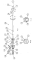
- the catheter assembly 100 includes a proximal end 102, a distal end 104, and a hub 106 connecting the proximal end 102 and the distal end 104.
- An elongated body 108 extends between the hub 106 and the distal end 104.
- the elongated body 108 is preferably comprised of a first catheter lumen 110, also shown as a venous lumen and a second catheter lumen 112, also known as an arterial lumen. While only two catheter lumens 110,112 are shown, those skilled in the art will recognize that the catheter assembly 100 may include more than two lumens 110,112.
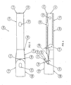
- Figs. 4, 5, and 6 show an enlarged perspective view, an enlarged.top plan view and an enlarged side view, respectively, of the distal end 104 of the catheter assembly 100.
- a transition portion 119 of the first lumen 110 disposed between the first distal tip and the second distal tip transitions the cross-section of the first lumen 110 from the D-shape shown in Fig. 2 to the generally circular cross section shape shown in Fig. 3.
- the body 108 is constructed from a polymer or elastomer, such as carbothane, with an approximately 20% barium sulfat/pellethane composition to aid in locating the body 108 within the patient's vessel after insertion, such as by ultrasound and fluoroscopy.
- a polymer or elastomer such as carbothane
- barium sulfat/pellethane composition to aid in locating the body 108 within the patient's vessel after insertion, such as by ultrasound and fluoroscopy.
- the body 108 has a hardness of approximately 80-A on the Shore durometer scale, although those skilled in the art will recognize that the body 108 may be harder or softer.
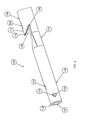
- a catheter tissue ingrowth cuff 124 is disposed along an exterior of the body 108 between the second distal tip 116 and the hub 106.
- the catheter tissue ingrowth cuff 124 is used for chronic catheter insertions, wherein the catheter assembly 100 is intended to be inserted into the patient for extended periods of time, such as for several months.
- the catheter tissue ingrowth cuff 124 is disposed within a subcutaneous tunnel according to methods known by those skilled in the art.
- the catheter tissue ingrowth cuff 124 is constructed from a generally coarse fabric material, such as a polyester or DACRON®, to enable ingrowing subcutaneous/skin tissue to engage the material and secure the catheter ingrowth cuff 124 to the subcutaneous/skin tissue.
- the catheter assembly 100 need not be subcutaneously tunnelled, and the catheter ingrowth cuff 124 may be omitted.
- the proximal end 102 of the catheter assembly 100 includes a first extension tube 130 that fluidly communicates with the first lumen 110 at a distal end 132 of the first extension tube through a first hub conduit 133.
- the first hub conduit 133 transitions from a generally circular cross section at the first extension tube 130 to a generally D-shaped cross section at the first lumen 110.
- the proximal end 102 of the catheter assembly 100 also includes a second extension tube 140 that fluidly communicates with the second lumen 112 at a distal end 142 of the second extension tube 140 through a second hub conduit 143.
- the second hub conduit 143 transitions from a generally circular cross section at the second extension tube 140 to a generally D-shaped cross section at the second lumen 112.
- a first clamp 138 such as a Roberts clamp is preferably disposed over the first extension tube 130 between the proximal end 134 and the distal end 132 of the first extension tube 130
- a second clamp 148 is preferably disposed over the second extension tube 140 between the proximal end 144 and the distal end 142 of the second extension tube 140.
- the first and second clamps 138,148 serve to releasably secure each of the first and second extension tubes 130,140, respectively, preventing fluid flow through each of the first and second extension tubes 130, 140 when the respective clamp 138,148 is in the closed position.
- the first lumen 110 preferably includes at least one and, more preferably, a plurality of first side ports 154, each being disposed in a plane generally perpendicular to the plane of the sidewall 118.
- each of the plurality of first side ports 154 is generally circular, although those skilled in the art will recognize that the first side ports 154 may be other shapes.
- the first distal tip 114 includes a generally circular bevel to facilitate a smooth transition between the first distal tip 114 and the body of the first lumen 110, and to reduce the risk of the first distal tip 114 snagging the wall of the blood vessel during insertion.
- the second distal tip 116 of the second lumen 112 is generally parabolic in shape and extends obliquely away from the sidewall 118 distally toward the first distal opening 151.
- the generally parabolic shape of the second distal tip 116 forms an overhanging lip, as seen in Figs. 1, 4, and 6.
- the second distal tip 116 of the second lumen 112 extends at an angle ⁇ 1 of approximately 37.5 degrees relative to the plane of the sidewall 118, although those skilled in the art will recognize that the angle ⁇ 1 may be other than 37.5 degrees.
- the second distal tip 116 preferably includes a second distal opening 155 and a second guide wire opening 156 that is disposed proximally of the second distal opening 155.
- the second guide wire opening 156 is generally oblong or oval in shape, with a major axis of the second guide wire opening 156 extending parallel to a major axis of the body 108.
- the transition portion 119 preferably includes a tapered wall 158 that angles at an angle 82 of approximately 30 degrees from the plane of the sidewall 118.
- a cavity 160 is formed between the tapered wall 158 and the second distal tip 116. The cavity 160 and the oblique shape of the second distal tip 116 assist in blood flow into the second lumen 112 through the second distal tip opening 155 during hemodialysis, as will be described in more detail later herein.
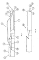
- the catheter assembly 100 is inserted over the guide wire. This insertion technique eliminates the need for a sheath to be inserted over the guide wire, greatly reducing the risk of air embolism.
- the proximal end 162 of the guide wire 160 is next pulled longitudinally along the exterior of the first lumen 110 and over the second distal tip 116 to the second guide wire opening 156, where the proximal end 162 of the guide wire 160 is inserted through the second guide wire opening 156 and into the second lumen 112.
- the proximal end 162 of the guide wire 160 is inserted through the second lumen 112 and pushed through the second lumen 112 until the proximal end 162 of the guide wire 160 exits the catheter assembly 100.
- the guide wire 160 As the guide wire 160 is pulled through both the first guide wire opening 152 and the second guide wire opening 156, the guide wire 160 between the first guide wire opening 152 and the second guide wire opening 156 engages the second distal tip 116 and directs the second distal tip 116 into the cavity 160, as shown in Fig. 7. With the second distal tip 116 in this position, the distal end 104 of the catheter assembly 100 may be inserted into the vessel more directly, preventing the second distal tip 116 from catching on the wall of the blood vessel and potentially snagging on the wall of the vessel. The distal end 104 of the catheter assembly 100 is inserted as far into the vessel as desired by the physician, and as confirmed by fluoroscopy.
- first and second connectors 136, 146 are connected in fluid communication to respective fluid inlets and outlets of a hemodialysis unit (not shown), or other fluid transfer equipment (not shown) and dialysis may now begin.
- the blood drawn into the second lumen 112 flows to the hemodialysis machine where the blood is cleaned and processed.
- the blood is then pumped through the first lumen 110 for discharge back into the vessel.
- the first distal opening 151 and the first side ports 154 provide discharge ports for the blood to be discharged from the first lumen 110.
- a distal end 204 of an alternate embodiment of a catheter assembly 200 having an alternate first distal tip 214 is shown in Fig. 8.
- the alternate first distal tip 214 includes a plurality of side ports 254 that are each generally semi-circular and end at the most distal portion of the first distal tip 214, merging with the first distal opening 251.
Landscapes
- Health & Medical Sciences (AREA)
- Life Sciences & Earth Sciences (AREA)
- Hematology (AREA)
- Animal Behavior & Ethology (AREA)
- Engineering & Computer Science (AREA)
- Anesthesiology (AREA)
- Biomedical Technology (AREA)
- Heart & Thoracic Surgery (AREA)
- Biophysics (AREA)
- Pulmonology (AREA)
- General Health & Medical Sciences (AREA)
- Public Health (AREA)
- Veterinary Medicine (AREA)
- Media Introduction/Drainage Providing Device (AREA)
- Materials For Medical Uses (AREA)
- Surgical Instruments (AREA)
Claims (11)
- Eine Mehrfachlumen-Katheter-Anordnung (100, 200) aufweisend einen länglichen Körper (108) mit einem proximalen Ende (102) und einem distalen Ende (104, 204), einem ersten Lumen (110) mit einer sich zwischen dem proximalen (102) und dem distalen Ende (104, 204) erstreckenden Seitenwand (118), einer am distalen Ende befindlichen ersten distalen Öffnung (151, 251), einer ersten Führungsdrahtöffnung (152), die sich proximal des distalen Endes befindet und mit der Seitenwand (118) koplanar ist, und einem zweiten Lumen (112), das mit der Seitenwand (118) verbunden ist und sich zwischen dem proximalen Ende (102) und einem zu dem distalen Ende (104, 204) proximalen zweiten distalen Ende (116) erstreckt, wobei das zweite Lumen (112) eine zweite Öffnung (155) enthält, die sich schräg von der Seitenwand (118) distal zur ersten Öffnung (151) hin erstreckt,
gekennzeichnet durch
eine zweite Führungsdrahtöffnung (156), die sich proximal der zweiten Öffnung (155) und in einer zur Seitenwand (118) im Wesentlichen parallelen Ebene befindet. - Die Mehrfachlumen-Katheter-Anordnung (100, 200) nach Anspruch 1, welche ferner eine mit dem proximalen Ende (102) des Körpers (108) verbundene Nabe (106) aufweist.
- Die Mehrfachlumen-Katheter-Anordnung (100, 200) nach Anspruch 1, bei welcher das erste Lumen (110) ferner zumindest eine nächst dem distalen Ende (104, 204) befindliche Öffnung (154, 254) aufweist.
- Die Mehrfachlumen-Katheter-Anordnung (100, 200) nach Anspruch 1, bei welcher die distale Öffnung (104, 204) sich in einer zur Ebene der Seitenwand (118) im Wesentlichen senkrechten Ebene befindet.
- Die Mehrfachlumen-Katheter-Anordnung (100, 200) nach Anspruch 1, bei welcher die erste distale Öffnung (104, 204) im Wesentlichen kreisrund ist.
- Die Mehrfachlumen-Katheter-Anordnung (100, 200) nach Anspruch 1, bei welcher das erste Lumen (110) im Wesentlichen D-förmigen Querschitt nächst der zweiten Öffnung (155) hat.
- Die Mehrfachlumen-Katheter-Anordnung (100, 200) nach Anspruch 1, bei welcher das zweite Lumen (112) im Wesentlichen D-förmigen Querschnitt hat.
- Die Mehrfachlumen-Katheter-Anordnung (100, 200) nach Anspruch 1, bei welcher der Körper (108) im Wesentlichen runden Querschnitt hat.
- Die Mehrfachlumen-Katheter-Anordnung (100, 200) nach Anspruch 1, bei welcher die zweite Öffnung (155) spitz zulaufend ist.
- Die Mehrfachlumen-Katheter-Anordnung (100, 200) nach Anspruch 1, bei welcher die erste Führungsdrahtöffnung(152) im Wesentlichen oval geformt ist.
- Die Mehrfachlumen-Katheter-Anordnung (100, 200) nach Anspruch 1, bei welcher die zweite Führungsdrahtöffnung(156) im Wesentlichen oval geformt ist.
Applications Claiming Priority (3)
| Application Number | Priority Date | Filing Date | Title |
|---|---|---|---|
| US40593702P | 2002-08-23 | 2002-08-23 | |
| US405937P | 2002-08-23 | ||
| PCT/US2003/026163 WO2004018016A2 (en) | 2002-08-23 | 2003-08-21 | Shielded tip catheter |
Publications (3)
| Publication Number | Publication Date |
|---|---|
| EP1534372A2 EP1534372A2 (de) | 2005-06-01 |
| EP1534372A4 EP1534372A4 (de) | 2005-08-17 |
| EP1534372B1 true EP1534372B1 (de) | 2006-07-05 |
Family
ID=31946947
Family Applications (1)
| Application Number | Title | Priority Date | Filing Date |
|---|---|---|---|
| EP03793206A Expired - Lifetime EP1534372B1 (de) | 2002-08-23 | 2003-08-21 | Katheter mit abgeschirmter spitze |
Country Status (6)
| Country | Link |
|---|---|
| EP (1) | EP1534372B1 (de) |
| AT (1) | ATE332163T1 (de) |
| AU (1) | AU2003258317A1 (de) |
| CA (1) | CA2495687C (de) |
| DE (1) | DE60306659T2 (de) |
| WO (1) | WO2004018016A2 (de) |
Families Citing this family (1)
| Publication number | Priority date | Publication date | Assignee | Title |
|---|---|---|---|---|
| EP1933920A4 (de) * | 2005-10-11 | 2010-12-29 | Flowmedica Inc | Gefässschleuse mit variabler lumenkonstruktion |
Family Cites Families (6)
| Publication number | Priority date | Publication date | Assignee | Title |
|---|---|---|---|---|
| US5273042A (en) * | 1987-10-28 | 1993-12-28 | Medical Parameters, Inc. | Guidewire advancement method |
| CA1330285C (en) * | 1987-12-22 | 1994-06-21 | Geoffrey S. Martin | Triple lumen catheter |
| US5312328A (en) * | 1991-01-11 | 1994-05-17 | Baxter International Inc. | Ultra-sound catheter for removing obstructions from tubular anatomical structures such as blood vessels |
| US5405341A (en) * | 1993-06-03 | 1995-04-11 | Med-Pro Design, Inc. | Catheter with multiple lumens |
| US6117153A (en) * | 1996-10-03 | 2000-09-12 | Interventional Technologies, Inc. | Neovascularization catheter |
| CA2320377C (en) * | 1998-02-24 | 2008-07-08 | Boston Scientific Limited | High flow rate dialysis catheters and related methods |
-
2003
- 2003-08-21 DE DE60306659T patent/DE60306659T2/de not_active Expired - Lifetime
- 2003-08-21 AU AU2003258317A patent/AU2003258317A1/en not_active Abandoned
- 2003-08-21 EP EP03793206A patent/EP1534372B1/de not_active Expired - Lifetime
- 2003-08-21 WO PCT/US2003/026163 patent/WO2004018016A2/en not_active Ceased
- 2003-08-21 AT AT03793206T patent/ATE332163T1/de not_active IP Right Cessation
- 2003-08-21 CA CA002495687A patent/CA2495687C/en not_active Expired - Lifetime
Also Published As
| Publication number | Publication date |
|---|---|
| EP1534372A4 (de) | 2005-08-17 |
| WO2004018016A2 (en) | 2004-03-04 |
| AU2003258317A8 (en) | 2004-03-11 |
| EP1534372A2 (de) | 2005-06-01 |
| CA2495687C (en) | 2008-05-20 |
| DE60306659D1 (de) | 2006-08-17 |
| AU2003258317A1 (en) | 2004-03-11 |
| CA2495687A1 (en) | 2004-03-04 |
| WO2004018016A3 (en) | 2005-01-13 |
| ATE332163T1 (de) | 2006-07-15 |
| DE60306659T2 (de) | 2007-06-28 |
Similar Documents
| Publication | Publication Date | Title |
|---|---|---|
| US7066925B2 (en) | Method of using a shielded tip catheter | |
| US7011645B2 (en) | Dialysis catheter | |
| EP1225934B1 (de) | Bolusspitzengestaltung für einen mehrlumigen katheter | |
| US20040176739A1 (en) | Catheter tunneler and adapter | |
| US7077829B2 (en) | Dialysis catheter | |
| JP4372518B2 (ja) | 血液処理カテーテル組立体 | |
| CN101909672B (zh) | 包括横向远侧开口的分裂末端导管 | |
| US8905998B2 (en) | Catheter tunneler adapter and methods of assembly to a catheter and use | |
| EP1432462B1 (de) | Katheter | |
| US7074213B2 (en) | Dialysis catheter | |
| US6682498B2 (en) | Methods and systems for subcutaneous graft implantation | |
| US7575563B2 (en) | Blood treatment catheter assembly | |
| US20040097903A1 (en) | Removable catheter hub | |
| EP1694377B1 (de) | Verteilerkopf für katheter | |
| JP2012228531A (ja) | 案内用鞘とカテーテルとの組合せ | |
| EP1534372B1 (de) | Katheter mit abgeschirmter spitze | |
| US8708956B2 (en) | Multi-lumen catheter with protected tip | |
| WO2007145796A2 (en) | Multi-lumen catheter with protected tip | |
| JP2007007042A (ja) | 多導穴カテーテル、同組立物及び同組立物の作動方法 | |
| WO2004037331A1 (en) | Dialysis catheter |
Legal Events
| Date | Code | Title | Description |
|---|---|---|---|
| PUAI | Public reference made under article 153(3) epc to a published international application that has entered the european phase |
Free format text: ORIGINAL CODE: 0009012 |
|
| 17P | Request for examination filed |
Effective date: 20050311 |
|
| AK | Designated contracting states |
Kind code of ref document: A2 Designated state(s): AT BE BG CH CY CZ DE DK EE ES FI FR GB GR HU IE IT LI LU MC NL PT RO SE SI SK TR |
|
| AX | Request for extension of the european patent |
Extension state: AL LT LV MK |
|
| A4 | Supplementary search report drawn up and despatched |
Effective date: 20050704 |
|
| DAX | Request for extension of the european patent (deleted) | ||
| GRAP | Despatch of communication of intention to grant a patent |
Free format text: ORIGINAL CODE: EPIDOSNIGR1 |
|
| GRAS | Grant fee paid |
Free format text: ORIGINAL CODE: EPIDOSNIGR3 |
|
| GRAA | (expected) grant |
Free format text: ORIGINAL CODE: 0009210 |
|
| AK | Designated contracting states |
Kind code of ref document: B1 Designated state(s): AT BE BG CH CY CZ DE DK EE ES FI FR GB GR HU IE IT LI LU MC NL PT RO SE SI SK TR |
|
| PG25 | Lapsed in a contracting state [announced via postgrant information from national office to epo] |
Ref country code: SI Free format text: LAPSE BECAUSE OF FAILURE TO SUBMIT A TRANSLATION OF THE DESCRIPTION OR TO PAY THE FEE WITHIN THE PRESCRIBED TIME-LIMIT Effective date: 20060705 Ref country code: LI Free format text: LAPSE BECAUSE OF FAILURE TO SUBMIT A TRANSLATION OF THE DESCRIPTION OR TO PAY THE FEE WITHIN THE PRESCRIBED TIME-LIMIT Effective date: 20060705 Ref country code: IT Free format text: LAPSE BECAUSE OF FAILURE TO SUBMIT A TRANSLATION OF THE DESCRIPTION OR TO PAY THE FEE WITHIN THE PRESCRIBED TIME-LIMIT;WARNING: LAPSES OF ITALIAN PATENTS WITH EFFECTIVE DATE BEFORE 2007 MAY HAVE OCCURRED AT ANY TIME BEFORE 2007. THE CORRECT EFFECTIVE DATE MAY BE DIFFERENT FROM THE ONE RECORDED. Effective date: 20060705 Ref country code: SK Free format text: LAPSE BECAUSE OF FAILURE TO SUBMIT A TRANSLATION OF THE DESCRIPTION OR TO PAY THE FEE WITHIN THE PRESCRIBED TIME-LIMIT Effective date: 20060705 Ref country code: AT Free format text: LAPSE BECAUSE OF FAILURE TO SUBMIT A TRANSLATION OF THE DESCRIPTION OR TO PAY THE FEE WITHIN THE PRESCRIBED TIME-LIMIT Effective date: 20060705 Ref country code: BE Free format text: LAPSE BECAUSE OF FAILURE TO SUBMIT A TRANSLATION OF THE DESCRIPTION OR TO PAY THE FEE WITHIN THE PRESCRIBED TIME-LIMIT Effective date: 20060705 Ref country code: CH Free format text: LAPSE BECAUSE OF FAILURE TO SUBMIT A TRANSLATION OF THE DESCRIPTION OR TO PAY THE FEE WITHIN THE PRESCRIBED TIME-LIMIT Effective date: 20060705 Ref country code: CZ Free format text: LAPSE BECAUSE OF FAILURE TO SUBMIT A TRANSLATION OF THE DESCRIPTION OR TO PAY THE FEE WITHIN THE PRESCRIBED TIME-LIMIT Effective date: 20060705 Ref country code: NL Free format text: LAPSE BECAUSE OF FAILURE TO SUBMIT A TRANSLATION OF THE DESCRIPTION OR TO PAY THE FEE WITHIN THE PRESCRIBED TIME-LIMIT Effective date: 20060705 Ref country code: RO Free format text: LAPSE BECAUSE OF FAILURE TO SUBMIT A TRANSLATION OF THE DESCRIPTION OR TO PAY THE FEE WITHIN THE PRESCRIBED TIME-LIMIT Effective date: 20060705 Ref country code: FI Free format text: LAPSE BECAUSE OF FAILURE TO SUBMIT A TRANSLATION OF THE DESCRIPTION OR TO PAY THE FEE WITHIN THE PRESCRIBED TIME-LIMIT Effective date: 20060705 |
|
| REG | Reference to a national code |
Ref country code: GB Ref legal event code: FG4D |
|
| REG | Reference to a national code |
Ref country code: CH Ref legal event code: EP |
|
| REG | Reference to a national code |
Ref country code: IE Ref legal event code: FG4D |
|
| REF | Corresponds to: |
Ref document number: 60306659 Country of ref document: DE Date of ref document: 20060817 Kind code of ref document: P |
|
| PG25 | Lapsed in a contracting state [announced via postgrant information from national office to epo] |
Ref country code: MC Free format text: LAPSE BECAUSE OF NON-PAYMENT OF DUE FEES Effective date: 20060831 |
|
| PG25 | Lapsed in a contracting state [announced via postgrant information from national office to epo] |
Ref country code: DK Free format text: LAPSE BECAUSE OF FAILURE TO SUBMIT A TRANSLATION OF THE DESCRIPTION OR TO PAY THE FEE WITHIN THE PRESCRIBED TIME-LIMIT Effective date: 20061005 Ref country code: BG Free format text: LAPSE BECAUSE OF FAILURE TO SUBMIT A TRANSLATION OF THE DESCRIPTION OR TO PAY THE FEE WITHIN THE PRESCRIBED TIME-LIMIT Effective date: 20061005 Ref country code: SE Free format text: LAPSE BECAUSE OF FAILURE TO SUBMIT A TRANSLATION OF THE DESCRIPTION OR TO PAY THE FEE WITHIN THE PRESCRIBED TIME-LIMIT Effective date: 20061005 |
|
| PG25 | Lapsed in a contracting state [announced via postgrant information from national office to epo] |
Ref country code: ES Free format text: LAPSE BECAUSE OF FAILURE TO SUBMIT A TRANSLATION OF THE DESCRIPTION OR TO PAY THE FEE WITHIN THE PRESCRIBED TIME-LIMIT Effective date: 20061016 |
|
| NLV1 | Nl: lapsed or annulled due to failure to fulfill the requirements of art. 29p and 29m of the patents act | ||
| PG25 | Lapsed in a contracting state [announced via postgrant information from national office to epo] |
Ref country code: PT Free format text: LAPSE BECAUSE OF FAILURE TO SUBMIT A TRANSLATION OF THE DESCRIPTION OR TO PAY THE FEE WITHIN THE PRESCRIBED TIME-LIMIT Effective date: 20061205 |
|
| ET | Fr: translation filed | ||
| PLBE | No opposition filed within time limit |
Free format text: ORIGINAL CODE: 0009261 |
|
| STAA | Information on the status of an ep patent application or granted ep patent |
Free format text: STATUS: NO OPPOSITION FILED WITHIN TIME LIMIT |
|
| 26N | No opposition filed |
Effective date: 20070410 |
|
| PG25 | Lapsed in a contracting state [announced via postgrant information from national office to epo] |
Ref country code: GR Free format text: LAPSE BECAUSE OF FAILURE TO SUBMIT A TRANSLATION OF THE DESCRIPTION OR TO PAY THE FEE WITHIN THE PRESCRIBED TIME-LIMIT Effective date: 20061006 |
|
| PG25 | Lapsed in a contracting state [announced via postgrant information from national office to epo] |
Ref country code: EE Free format text: LAPSE BECAUSE OF FAILURE TO SUBMIT A TRANSLATION OF THE DESCRIPTION OR TO PAY THE FEE WITHIN THE PRESCRIBED TIME-LIMIT Effective date: 20060705 |
|
| PG25 | Lapsed in a contracting state [announced via postgrant information from national office to epo] |
Ref country code: LU Free format text: LAPSE BECAUSE OF NON-PAYMENT OF DUE FEES Effective date: 20060821 Ref country code: TR Free format text: LAPSE BECAUSE OF FAILURE TO SUBMIT A TRANSLATION OF THE DESCRIPTION OR TO PAY THE FEE WITHIN THE PRESCRIBED TIME-LIMIT Effective date: 20060705 Ref country code: HU Free format text: LAPSE BECAUSE OF FAILURE TO SUBMIT A TRANSLATION OF THE DESCRIPTION OR TO PAY THE FEE WITHIN THE PRESCRIBED TIME-LIMIT Effective date: 20070106 |
|
| PG25 | Lapsed in a contracting state [announced via postgrant information from national office to epo] |
Ref country code: CY Free format text: LAPSE BECAUSE OF FAILURE TO SUBMIT A TRANSLATION OF THE DESCRIPTION OR TO PAY THE FEE WITHIN THE PRESCRIBED TIME-LIMIT Effective date: 20060705 |
|
| REG | Reference to a national code |
Ref country code: FR Ref legal event code: PLFP Year of fee payment: 13 |
|
| REG | Reference to a national code |
Ref country code: FR Ref legal event code: PLFP Year of fee payment: 14 |
|
| REG | Reference to a national code |
Ref country code: FR Ref legal event code: PLFP Year of fee payment: 15 |
|
| REG | Reference to a national code |
Ref country code: FR Ref legal event code: PLFP Year of fee payment: 16 |
|
| PGFP | Annual fee paid to national office [announced via postgrant information from national office to epo] |
Ref country code: FR Payment date: 20210714 Year of fee payment: 19 Ref country code: IE Payment date: 20210810 Year of fee payment: 19 |
|
| PGFP | Annual fee paid to national office [announced via postgrant information from national office to epo] |
Ref country code: DE Payment date: 20210713 Year of fee payment: 19 Ref country code: GB Payment date: 20210714 Year of fee payment: 19 |
|
| REG | Reference to a national code |
Ref country code: DE Ref legal event code: R119 Ref document number: 60306659 Country of ref document: DE |
|
| GBPC | Gb: european patent ceased through non-payment of renewal fee |
Effective date: 20220821 |
|
| PG25 | Lapsed in a contracting state [announced via postgrant information from national office to epo] |
Ref country code: IE Free format text: LAPSE BECAUSE OF NON-PAYMENT OF DUE FEES Effective date: 20220821 Ref country code: FR Free format text: LAPSE BECAUSE OF NON-PAYMENT OF DUE FEES Effective date: 20220831 Ref country code: DE Free format text: LAPSE BECAUSE OF NON-PAYMENT OF DUE FEES Effective date: 20230301 |
|
| PG25 | Lapsed in a contracting state [announced via postgrant information from national office to epo] |
Ref country code: GB Free format text: LAPSE BECAUSE OF NON-PAYMENT OF DUE FEES Effective date: 20220821 |