EP1533938A1 - Transceiver mit Steuerungsvorrichtung fur Authentifizierung - Google Patents
Transceiver mit Steuerungsvorrichtung fur Authentifizierung Download PDFInfo
- Publication number
- EP1533938A1 EP1533938A1 EP04090443A EP04090443A EP1533938A1 EP 1533938 A1 EP1533938 A1 EP 1533938A1 EP 04090443 A EP04090443 A EP 04090443A EP 04090443 A EP04090443 A EP 04090443A EP 1533938 A1 EP1533938 A1 EP 1533938A1
- Authority
- EP
- European Patent Office
- Prior art keywords
- transceiver
- host
- key
- fiber optic
- authentication
- Prior art date
- Legal status (The legal status is an assumption and is not a legal conclusion. Google has not performed a legal analysis and makes no representation as to the accuracy of the status listed.)
- Withdrawn
Links
- 239000000835 fiber Substances 0.000 claims description 54
- 230000003287 optical effect Effects 0.000 claims description 13
- 238000000034 method Methods 0.000 claims description 10
- 238000009434 installation Methods 0.000 claims description 4
- 230000004044 response Effects 0.000 claims description 3
- 238000004458 analytical method Methods 0.000 claims description 2
- 230000008878 coupling Effects 0.000 description 12
- 238000010168 coupling process Methods 0.000 description 12
- 238000005859 coupling reaction Methods 0.000 description 12
- 238000004891 communication Methods 0.000 description 9
- 238000010586 diagram Methods 0.000 description 8
- 238000013154 diagnostic monitoring Methods 0.000 description 5
- 238000012546 transfer Methods 0.000 description 4
- 230000006870 function Effects 0.000 description 3
- 238000012544 monitoring process Methods 0.000 description 3
- 230000008901 benefit Effects 0.000 description 2
- 125000004122 cyclic group Chemical group 0.000 description 2
- RGNPBRKPHBKNKX-UHFFFAOYSA-N hexaflumuron Chemical compound C1=C(Cl)C(OC(F)(F)C(F)F)=C(Cl)C=C1NC(=O)NC(=O)C1=C(F)C=CC=C1F RGNPBRKPHBKNKX-UHFFFAOYSA-N 0.000 description 2
- 230000009471 action Effects 0.000 description 1
- 238000005516 engineering process Methods 0.000 description 1
- 230000002708 enhancing effect Effects 0.000 description 1
- 230000009474 immediate action Effects 0.000 description 1
- 238000004519 manufacturing process Methods 0.000 description 1
- 238000005259 measurement Methods 0.000 description 1
- 238000012545 processing Methods 0.000 description 1
- 238000011084 recovery Methods 0.000 description 1
- 239000004065 semiconductor Substances 0.000 description 1
Images


Classifications
-
- H—ELECTRICITY
- H04—ELECTRIC COMMUNICATION TECHNIQUE
- H04L—TRANSMISSION OF DIGITAL INFORMATION, e.g. TELEGRAPHIC COMMUNICATION
- H04L9/00—Cryptographic mechanisms or cryptographic arrangements for secret or secure communications; Network security protocols
- H04L9/32—Cryptographic mechanisms or cryptographic arrangements for secret or secure communications; Network security protocols including means for verifying the identity or authority of a user of the system or for message authentication, e.g. authorization, entity authentication, data integrity or data verification, non-repudiation, key authentication or verification of credentials
- H04L9/3263—Cryptographic mechanisms or cryptographic arrangements for secret or secure communications; Network security protocols including means for verifying the identity or authority of a user of the system or for message authentication, e.g. authorization, entity authentication, data integrity or data verification, non-repudiation, key authentication or verification of credentials involving certificates, e.g. public key certificate [PKC] or attribute certificate [AC]; Public key infrastructure [PKI] arrangements
-
- H—ELECTRICITY
- H04—ELECTRIC COMMUNICATION TECHNIQUE
- H04L—TRANSMISSION OF DIGITAL INFORMATION, e.g. TELEGRAPHIC COMMUNICATION
- H04L9/00—Cryptographic mechanisms or cryptographic arrangements for secret or secure communications; Network security protocols
- H04L9/32—Cryptographic mechanisms or cryptographic arrangements for secret or secure communications; Network security protocols including means for verifying the identity or authority of a user of the system or for message authentication, e.g. authorization, entity authentication, data integrity or data verification, non-repudiation, key authentication or verification of credentials
- H04L9/3271—Cryptographic mechanisms or cryptographic arrangements for secret or secure communications; Network security protocols including means for verifying the identity or authority of a user of the system or for message authentication, e.g. authorization, entity authentication, data integrity or data verification, non-repudiation, key authentication or verification of credentials using challenge-response
Definitions
- Fiber optic transceivers are used in a variety of applications, including storage area networks (SANs), local area networks (LANs), Fibre Channel, Gigabit Ethernet, and SONET applications. Fiber optic transceivers can be used as the network interface in mainframe computers, workstations, servers, and storage devices. Fiber optic transceivers can also be used in abroad range of network devices, such as bridges, routers, hubs, and local and wide area switches.
- SANs storage area networks
- LANs local area networks
- Fibre Channel Fibre Channel
- Gigabit Ethernet Gigabit Ethernet
- SONET SONET applications.
- Fiber optic transceivers can be used as the network interface in mainframe computers, workstations, servers, and storage devices. Fiber optic transceivers can also be used in abroad range of network devices, such as bridges, routers, hubs, and local and wide area switches.
- Fiber optic transceivers include a fiber optic receiver and a fiber optic transmitter.
- the fiber optic receiver converts optical serial data to electrical serial data and the fiber optic transmitter converts electrical serial data to optical serial data.
- a majority of fiber optic transceivers include power control circuits, diagnostic circuits, and other circuits for enhancing the functionality of the fiber optic transceivers.
- Fiber optic transceivers are typically critical components in a network system. If a fiber optic transceiver fails during operation of the network system, the entire network system can fail. Network system failure can result in disruptions of services and lost revenues. Because of the critical nature of fiber optic transceivers, some users of fiber optic transceivers require the manufacturers or suppliers of the fiber optic transceivers to indemnify the user for any losses incurred as a result of a failure of a fiber optic transceiver. In response to this potential liability, manufacturers and suppliers have developed strict quality standards that must be met before their fiber optic transceivers are. certified for use in systems.
- a typical problem for users, manufacturers, and suppliers of fiber optic transceivers is the gray market.
- Sometimes cloned fiber optic transceivers are used in place of original certified fiber optic transceivers after the original certified fiber optic transceivers reach their end of life or when additional fiber optic transceivers are being added to expand a system.
- the use of cloned fiber optic transceivers can negatively affect the user and the manufacturer and supplier of the authentic fiber optic transceivers.
- the user is harmed because the cloned fiber optic transceivers are of unknown quality and have not been certified as meeting specified quality standards.
- the warranty on the system may be invalidated.
- the manufacturer and supplier of the authentic fiber optic transceiver may not service or support the cloned fiber optic transceiver.
- the manufacturer or supplier of the authentic certified fiber optic transceiver will not assume liability for the failure. The customer would be required to attempt to recover from the manufacturer or supplier of the cloned fiber optic transceiver.
- Cloned fiber optic transceivers harm the manufacturers and suppliers of authentic certified fiber optic transceivers due to loss of market share, loss of reputation, and liability issues.
- the reputation of a manufacturer or supplier for quality can be harmed if users believe a cloned fiber optic transceiver originated with the manufacturer or supplier of authentic certified fiber optic transceivers. Liability, warranty, service, and support issues are likely to arise between the user and the manufacturer or supplier when cloned fiber optic transceivers are used in place of authentic certified fiber optic transceivers.
- the transceiver comprises a transmitter configured to transmit data signals, a receiver configured to receive data signals, and a controller configured to encrypt a string and supply the encrypted string to authenticate the transceiver.
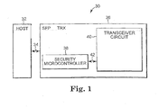
- FIG. 1 is a block diagram illustrating one embodiment of a portion of a network system 30.
- Network system 30 includes a host 32 and a transceiver 36.
- Host 32 is electrically coupled to transceiver 36 through communication link 34.
- Transceiver 36 includes a security microcontroller 38 and a transceiver circuit 40.
- Security microcontroller 38 is electrically coupled to transceiver circuit 40 through path 42.
- transceiver 36 is a small form factor pluggable (SFP) transceiver (TRX).
- SFP small form factor pluggable
- Host 32 is a mainframe computer, workstation, server, storage device, or network device such as a bridge, router, hub, or local or wide area switch. In other embodiments, host 32 is any suitable device that communicates with other devices through a transceiver.
- Transceiver 36 includes a housing for installing transceiver 36 in network system 30.
- transceiver 36 is compatible with RJ-45 style backpanels for high-end data communications and telecommunications applications and provides the advantages of fiber optic technology.
- transceiver 36 is designed for low cost storage area networks (SANs), local area networks (LANs), Fibre Channel, Gigabit Ethernet, and SONET applications.
- SANs storage area networks
- LANs local area networks
- Fibre Channel Fibre Channel
- Gigabit Ethernet Gigabit Ethernet
- SONET SONET applications.
- Transceiver 36 can be used as the network interface in mainframe computers, workstations, servers, and storage devices, and in a broad range of network devices, such as bridges, routers, hubs, and local and wide area switches.
- Security microcontroller 38 is built into transceiver 36 and disposed on a printed circuit board (PCB) that is not visible from the outside of transceiver 36.
- Security microcontroller 38 is configured to identify transceiver 36 to host 32.
- Security microcontroller 38 communicates to host 32 that transceiver 36 is an authentic transceiver and not a clone or copy.
- An authentic transceiver is a transceiver that has been certified by the manufacturer or supplier of the transceiver as meeting specified quality standards. This prevents a transceiver; such as transceiver 36, from being cloned and sold in the gray market.
- Transceiver circuit 40 includes a receiver and a transmitter.
- the receiver converts optical serial data received from an external device into electrical serial data to pass to host 32.
- the transmitter converts electrical serial data received from host 32 into optical serial data to pass to an external device.
- Transceiver circuit 40 is used to transmit and receive data between host 32 and other devices.
- transceiver 36 Upon installation of transceiver 36, host 32 communicates with security microcontroller 38 through communication link 34 to determine if transceiver 36 is authentic. If transceiver 36 is not authentic, transceiver 36 is rejected and does not function with host 32. If transceiver 36 is accepted, transceiver 36 functions with host 32. Once transceiver 36 is authenticated and accepted, host 32 uses transceiver 36 to transmit and receive data.
- Transceiver 36 includes security microcontroller 38, transceiver circuit 40, and communication link 34.
- Transceiver circuit 40 includes an automatic shutdown circuit 120, a laser driver 124, a switch 128, a transmitter (Tx) coupling unit 130, a power control circuit 140, a receiver 144, a receiver (Rx) coupling unit 148, and a digital diagnostic monitoring interface 152.
- the Rx coupling unit 148 includes a photodiode 150.
- the Tx coupling unit 130 includes a laser diode 132 and a monitor diode 136.
- the automatic shutdown circuit 120, laser driver 124, switch 128, Tx coupling unit 130, and power control circuit 140 are configured as a transmitter.
- Automatic shutdown circuit 120 is electrically coupled to laser driver 124 through path 121 and to switch 128 through path 122.
- Laser driver 124 is electrically coupled to switch 128 through path 126 and to power control circuit 140 through path 142.
- Switch 128 is electrically coupled to laser diode 132 through path 129 and laser diode 132 is optically coupled to monitor diode 136 through optical path 134.
- Monitor diode 136 is electrically coupled to power control circuit 140 and automatic shut down circuit 120 through path 138.
- Tx coupling unit 130 is coupled to fiber optic cable 118.
- the receiver 144 and Rx coupling unit 148 are configured as a receiver.
- Receiver 144 is electrically coupled to photodiode 150 through path 146.
- Rx coupling unit 148 is coupled to a fiber optic cable 119.
- Digital diagnostic monitoring interface 152 is electrically coupled to security microcontroller 38 through path 42.
- Communication link 34 includes a transmitter fault (Tx Fault) signal line 100, a transmitter disable (TxDis) signal line 102, a transmit data minus (TD-) signal line 104, and a transmit data plus (TD+) signal line 106.
- communication link 34 includes a receive data minus (RD-) signal line 108, a receive data plus (RD+) signal line 110, loss of signal (LOS) line 112, and an inter-integrated circuit (I2C) bus 114.
- I2C bus 114 can be replaced with another suitable communication bus.
- Transmitter fault signal line 100 is electrically coupled to automatic shutdown circuit 120.
- Transmitter disable signal line 102 is electrically coupled to automatic shutdown circuit 120 and laser driver 124 through path 121.
- Transmit data minus signal line 104 and transmit data plus signal line 106 are electrically coupled to laser driver 124.
- Receive data minus signal line 108, receive data plus signal line 110, and loss of signal line 112 are electrically coupled to receiver 144, and inter-integrated circuit bus 114 is electrically coupled to security microcontroller 38,
- Rx coupling unit 148 mechanically and optically couples transceiver 36 to fiber optic cable 119.
- An optical signal transmitted by an external device is received by photodiode 150 and converted by photodiode 150 to an electrical signal.
- the electrical signal is passed to receiver 144 through path 146.
- Receiver 144 converts the signal received from photodiode 150 into electrical serial data compatible with low voltage positive emitter coupled compatible logic (LVPECL).
- LVPECL compatible electrical serial data is passed to host 32 through signal lines RD- 108 and RD+ 110.
- the loss of signal on LOS signal line 112 indicates whether an optical signal is present at Rx coupling unit 148.
- Monitoring diode 136 monitors the optical output of laser diode 132 through optical path 134.
- monitoring diode 136 is mechanically built into Tx coupling unit 130.
- Monitoring diode 136 outputs a signal indicative of the output of laser diode 132 through path 13 8 to automatic shutdown circuit 120 and power control circuit 140.
- Laser driver circuit 124 drives the modulation and bias current of laser diode 132.
- the currents are controlled by power control circuit 140 to provide constant output power of laser diode 132 over varying temperatures and as the laser diode 132 ages.
- Power control circuit 140 uses the output of monitor diode 136 as a control signal to prevent the laser power from exceeding operating limits.
- Tx coupling unit 130 mechanically and optically couples transceiver 36 to fiber optic cable 118.
- Laser driver 124 receives a LVPECL compatible serial data signal from host 32 through TD- signal line 104 and TD+ signal line 106 and passes the signal to laser diode 132.
- Laser diode 132 converts the signal received from laser driver 124 into optical serial data and transmits the optical serial data through fiber optic cable 118.
- Shutdown circuit 120 automatically disables laser diode 132 and outputs a fault signal on Tx Fault signal line 100 if shutdown circuit 120 detects a laser fault. By disabling laser diode 132, shutdown circuit 120 provides laser eye safety. Shutdown circuit 120 communicates with switch 128 through path 122 to open or close switch 128 to disable or enable laser diode 132.
- transceiver 36 includes a supervisory circuit for controlling the power supply.
- the supervisory circuit provides an internal reset signal whenever the supply voltage drops below a reset threshold.
- the supervisory circuit keeps the reset signal active for at least 140 ms after the voltage has risen above the reset threshold. During this time, laser diode 132 is inactive.
- Host 32 can enable the laser driver 124 by providing a logic low level on TxDis signal line 102. Host 32 can disable the laser driver 124 by providing a logic high level on TxDis signal line 102.
- Digital diagnostic monitoring interface 152 continuously monitors transceiver 36 operating parameters.
- transceiver 36 features internal calibration. Measurements are taken and transceiver 3 6 is calibrated over varying operating temperatures and voltages to obtain normal operating parameter ranges for transceiver 36.
- digital diagnostic monitoring interface 152 generates diagnostic data that is compared to the normal operating parameter ranges by digitizing internal analog signals monitored by a diagnostic integrated circuit (IC).
- IC diagnostic integrated circuit
- the diagnostic IC has built in sensors that include alarm and warning thresholds. The threshold values are set during device manufacture and allow the user to determine when a particular value is outside of a normal operating parameter range.
- Digital diagnostic monitoring interface 152 outputs alarm and warning flags to security microcontroller 38 through path 42.
- Security microcontroller 38 passes the alarm and warning flags to host 32 through I2C bus 114.
- Alarm flags indicate conditions likely to be associated with an inoperational link that requires immediate action.
- Warning flags indicate conditions outside normal operating ranges, but not necessarily causes of immediate link failures.
- I2C bus 114 allows host 32 and security microcontroller 38 to communicate directly with each other over two active wires and a ground connection. Both host 32 and security microcontroller 38 can act as transmitters and receivers on the I2C bus, Host 32 is the bus master if host 32 initiates a data transfer to security microcontroller 38 and security microcontroller 38 is the bus slave for the data transfer. Security microcontroller 38 is the bus master if security microcontroller 38 initiates a data transfer to host 32 and host 32 is the bus slave for the data transfer.
- FIG. 3 is a block diagram illustrating one embodiment of security microcontroller 38.
- security microcontroller 38 is a single semiconductor chip.
- Security microcontroller 38 includes a voltage clock reset module 204, a read only memory (ROM) 206, a random access memory (RAM) 208, an electrically erasable and programmable read only memory (EEPROM) 210, a cryptography module 212, a central processing unit (CPU) 200, sleep mode logic sensors/filters and voltage regulator module 214, an interrupt module 216, a timer module 218, a cyclic redundancy check (CRC) module 220, a random number generator 222, an inter-integrated circuit (I2C) receiver-transmitter 224, a phase-locked loop (PLL) module 226, and an address/data bus 202.
- security microcontroller 38 does not include all of these components.
- I2C receiver-transmitter 224 can be replaced with another suitable receiver-transmitter.
- CPU 200 is electrically coupled to address/data bus 202.
- ROM 206 is electrically coupled to address/data bus 202 through path 207 and RAM 208 is electrically coupled to address/data bus 202 through path 209.
- EEPROM 210 is electrically coupled to address/data bus 202 through path 211 and cryptography module 212 is electrically coupled to address/data bus 202 through path 213.
- Interrupt module 216 is electrically coupled to address/data bus 202 through path 217 and timer module 218 is electrically coupled to address/data bus 202 through path 219.
- CRC module 220 is electrically coupled to address/data bus 202 through path 221 and random number generator 222 is electrically coupled to address/data bus 202 through path 223.
- I2C receiver-transmitter 224 is electrically coupled to address/data bus 202 through path 225 and PLL module 226 is electrically coupled to address/data bus 202 through path 227.
- Sleep mode logic sensor filters and voltage regulator module 214 is electrically coupled to CPU 200 through path 215 and voltage clock reset module 204 is electrically coupled to CPU 200 through path 205.
- CPU 200 controls the functioning of security microcontroller 38 and communicates with the other components of security microcontroller 38 directly or through address/data bus 202.
- ROM 206 stores operating system and application programs for security microcontroller 38.
- RAM 208 temporarily stores data and instructions for operating security microcontroller 38.
- EEPROM 210 stores operating parameters and other information relating to the operation of transceiver 36 and a public key/private key pair for authenticating security microcontroller 38.
- Cryptography module 212 performs encryption and decryption of communications between host 32 and security microcontroller 38.
- Random number generator 222 generates random numbers for use in cryptography module 212.
- I2C receiver-transmitter 224 transmits and receives communications from host 32.
- Voltage clock reset module 204 resets the voltage and clock for security microcontroller 38.
- Sleep mode logic sensors/filters and voltage regulator module 214 regulates the voltage in security microcontroller 38 and enables sleep mode for saving power in security microcontroller 38.
- Interrupt module 216 allows external circuits to initiate actions in security microcontroller 38.
- Timer module 218 is used for timing operations in security microcontroller 38.
- CRC module 220 performs cyclic redundancy checks on data passing to security microcontroller 38.
- PLL 226 synchronizes a clock in security microcontroller 38 with an external clock.
- Security microcontroller 38 authenticates transceiver 36 with host 32 upon installation of transceiver 36.
- each security microcontroller 38 is assigned a unique transceiver 36 specific public key/private key pair.
- the transceiver 36 specific public key is sealed (encrypted) using a private key that belongs to and is known only to the issuing authority for security microcontroller 38.
- the issuing authority is typically the OEM customer for whom security microcontroller 38 is manufactured.
- the transceiver 36 specific private key and sealed transceiver 36 specific public key are loaded into security microcontroller 3 8 in a private storage area, such as an area in EEPROM 210, where they are not directly accessible from outside security microcontroller 38.
- a global access code is associated with the transceiver 36 specific public key/private key pair for greater security.
- transceiver 36 Upon installation of transceiver 36 in system 30, host 32 attempts to authenticate transceiver 36. Host 32 sends a message to security microcontroller 38 requesting the sealed transceiver 36 specific public key of security microcontroller 38. If a global access code has been associated with the transceiver 36 specific public key/private key pair, the request message includes the access code.
- Security microcontroller 38 checks the global access code, if called for, and returns the sealed transceiver 36 specific public key associated with that access code.
- the sealed transceiver 36 specific public key serves as a certificate identification (ID) for security microcontroller 38.
- Host 32 unseals (decrypts) the sealed transceiver 36 specific public key using the known corresponding public key of the issuing authority.
- Host 32 completes the authentication of transceiver 36 by generating a random number and passing the random to security microcontroller 38.
- Security microcontroller 38 seals (encrypts) the random number using the transceiver 36 specific private key.
- host 32 generates an authentication string in place of the random number for authentication.
- security microcontroller 38 returns the result to host 32, host 32 uses the transceiver 36 specific public key obtained from the previously requested sealed transceiver 3 6 specific public key to decrypt the result.
- security microcontroller 38 contains the unique transceiver 36 specific private key associated with the transceiver 36 specific public key that was sealed by the issuing authority. Host 32 concludes that security microcontroller 38, and by extension transceiver 36 in which it is mounted, is authentic. If host 32 determines that transceiver 36 is authentic, host 32 accepts and uses transceiver 36. If, however, host 32 determines that transceiver 36 is not authentic, host 32 rejects and does not use transceiver 36.
- the public key cryptography system used to authenticate security microcontroller 38 can be any public key system that provides suitable encryption.
- the authentication application is self-contained, and does not involve existing infrastructure that limits its choice of encryption system.
- RSA is the cryptography method used to authenticate security microcontroller 38.
- elliptic curve cryptography (ECC) is used to authenticate security microcontroller 38. ECC has an advantage over RSA in that a shorter key length is required for suitable security compared to systems based on RSA.
- multiple unique transceiver 36 specific public key/private key pairs are generated and stored in each security microcontroller 38. Each key pair is associated with a different access code. Each of the transceiver specific public keys of the set of key pairs is sealed using a different private key from the issuing authority.
- the host system software is written to use one of the key pairs. A later revision or patch to the software, however, can switch to one of the other stored key pairs by changing the access code used. This provides a recovery strategy in case a transceiver specific public key/private key pair in use in one of the security microcontrollers is somehow discovered and used to create cloned security microcontrollers that can pass authentication.
- FIG. 4 is a flow diagram illustrating one embodiment of a method for authenticating a transceiver 36 including a security microcontroller 38 encoded with a transceiver 36 specific public key/private key pair.
- transceiver 36 is installed in a system 30.
- host 32 requests the certificate identification (encrypted transceiver 36 specific public key) from transceiver 36 be sent to host 32.
- transceiver 36 sends the certificate identification to host 32 from security microcontroller 38 through 12C bus 114.
- host 32 decrypts the certificate identification using a public key of the issuing authority and obtains the transceiver 36 specific public key.
- host 32 generates a random number.
- host 32 sends the random number to security microcontroller 38.
- security microcontroller 3 8 encrypts the original random number using the transceiver 36 specific private key.
- security microcontroller 38 sends the encrypted random number to host 32.
- host 32 decrypts the encrypted random number using the transceiver 36 specific public key.
- host 32 determines if the decrypted random number matches the original random number. If the decrypted random number matches the original random number, transceiver 36 is authentic and is accepted at 324. If the decrypted random number does not match the original random number, transceiver 36 is not authentic and is rejected at 322.
Landscapes
- Engineering & Computer Science (AREA)
- Computer Security & Cryptography (AREA)
- Computer Networks & Wireless Communication (AREA)
- Signal Processing (AREA)
- Small-Scale Networks (AREA)
- Optical Communication System (AREA)
Applications Claiming Priority (2)
| Application Number | Priority Date | Filing Date | Title |
|---|---|---|---|
| US10/718,753 US8165297B2 (en) | 2003-11-21 | 2003-11-21 | Transceiver with controller for authentication |
| US718753 | 2003-11-21 |
Publications (1)
| Publication Number | Publication Date |
|---|---|
| EP1533938A1 true EP1533938A1 (de) | 2005-05-25 |
Family
ID=34435791
Family Applications (1)
| Application Number | Title | Priority Date | Filing Date |
|---|---|---|---|
| EP04090443A Withdrawn EP1533938A1 (de) | 2003-11-21 | 2004-11-17 | Transceiver mit Steuerungsvorrichtung fur Authentifizierung |
Country Status (3)
| Country | Link |
|---|---|
| US (1) | US8165297B2 (de) |
| EP (1) | EP1533938A1 (de) |
| CN (2) | CN103475475B (de) |
Families Citing this family (42)
| Publication number | Priority date | Publication date | Assignee | Title |
|---|---|---|---|---|
| US8165297B2 (en) | 2003-11-21 | 2012-04-24 | Finisar Corporation | Transceiver with controller for authentication |
| EP1745572A4 (de) * | 2004-04-30 | 2010-12-08 | Utc Fire & Security Corp | Sicherheits-systemkommunikation mit verschlüsselung |
| US7970947B1 (en) * | 2005-03-10 | 2011-06-28 | Rockwell Collins, Inc. | Tactical targeting network technology small form factor user system |
| US20070180145A1 (en) * | 2006-01-27 | 2007-08-02 | Cisco Technology, Inc. (A California Corporation) | Pluggable transceiver module with encryption capability |
| US8762714B2 (en) * | 2007-04-24 | 2014-06-24 | Finisar Corporation | Protecting against counterfeit electronics devices |
| US9148286B2 (en) * | 2007-10-15 | 2015-09-29 | Finisar Corporation | Protecting against counterfeit electronic devices |
| WO2009059331A2 (en) * | 2007-11-02 | 2009-05-07 | Finisar Corporation | Anticounterfeiting means for optical communication components |
| US8819423B2 (en) * | 2007-11-27 | 2014-08-26 | Finisar Corporation | Optical transceiver with vendor authentication |
| US8117447B2 (en) * | 2008-01-10 | 2012-02-14 | Industrial Technology Research Institute | Authentication method employing elliptic curve cryptography |
| US9286493B2 (en) * | 2009-01-07 | 2016-03-15 | Clevx, Llc | Encryption bridge system and method of operation thereof |
| US8504821B2 (en) * | 2009-07-10 | 2013-08-06 | Finisar Corporation | Encrypted optoelectronic module |
| US20120008962A1 (en) * | 2010-07-09 | 2012-01-12 | Sumitomo Electric Device Innovations, Inc. | Controller for optical transceiver and a method to control the same |
| JP5776927B2 (ja) * | 2011-03-28 | 2015-09-09 | ソニー株式会社 | 情報処理装置及び方法、並びにプログラム |
| US8966234B1 (en) * | 2011-07-08 | 2015-02-24 | Cisco Technology, Inc. | Pluggable module subcomponent reset |
| US8954160B2 (en) * | 2011-09-02 | 2015-02-10 | Medtronic, Inc. | Detection of extracardiac stimulation by a cardiac rhythm management device |
| US9199087B2 (en) | 2011-11-21 | 2015-12-01 | Medtronic, Inc. | Apparatus and method for selecting a preferred pacing vector in a cardiac resynchronization device |
| WO2013086287A1 (en) | 2011-12-07 | 2013-06-13 | Adc Telecommunications, Inc. | Systems and methods for using active optical cable segments |
| IN2014KN02956A (de) | 2012-06-25 | 2015-05-08 | Adc Telecommunications Inc | |
| US9473361B2 (en) | 2012-07-11 | 2016-10-18 | Commscope Technologies Llc | Physical layer management at a wall plate device |
| US9351571B2 (en) | 2012-07-11 | 2016-05-31 | Manitowoc Foodservice Companies, Llc | Connection assembly for a base and a cabinet assembly of an ice maker |
| US9948614B1 (en) * | 2013-05-23 | 2018-04-17 | Rockwell Collins, Inc. | Remote device initialization using asymmetric cryptography |
| US9584327B2 (en) * | 2013-07-31 | 2017-02-28 | Arista Networks, Inc. | System and method for authentication for transceivers |
| US9641339B2 (en) | 2013-07-31 | 2017-05-02 | Arista Networks, Inc. | System and method for authentication for field replaceable units |
| KR20160118207A (ko) | 2013-09-24 | 2016-10-11 | 콤스코프 테크놀로지스, 엘엘씨 | 시뮬레이션되는 메모리 테이블 및 관리형 연결 지원을 갖는 플러그형 능동 광학 모듈 |
| CN104601229B (zh) * | 2013-11-01 | 2019-02-19 | 中兴通讯股份有限公司 | 光模块识别方法及装置 |
| US10178182B2 (en) * | 2014-11-24 | 2019-01-08 | Vivint, Inc. | Signal cloning |
| US9552006B1 (en) * | 2015-03-09 | 2017-01-24 | Inphi Corporation | Wideband low dropout voltage regulator with power supply rejection boost |
| US9825918B2 (en) | 2015-05-22 | 2017-11-21 | Nxp B.V. | Controller area network (CAN) device and method for operating a CAN device |
| US9935774B2 (en) | 2015-05-22 | 2018-04-03 | Nxp B.V. | Configurable cryptographic controller area network (CAN) device |
| US10095634B2 (en) * | 2015-05-22 | 2018-10-09 | Nxp B.V. | In-vehicle network (IVN) device and method for operating an IVN device |
| CN106470198B (zh) * | 2015-08-20 | 2021-02-23 | 中兴通讯股份有限公司 | 光传送网的身份验证方法、装置及系统 |
| JP6715931B2 (ja) * | 2015-11-19 | 2020-07-01 | エヌライト, インコーポレイテッドNlight, Inc. | レーザーフォールトトレランスおよびセルフキャリブレーションシステム |
| US11025034B2 (en) | 2016-08-31 | 2021-06-01 | Nlight, Inc. | Laser cooling system |
| CN109075974B (zh) * | 2016-10-25 | 2021-12-21 | 深圳市汇顶科技股份有限公司 | 指纹算法库与指纹传感器的绑定认证方法及指纹识别系统 |
| WO2018112220A1 (en) | 2016-12-15 | 2018-06-21 | Nlight, Inc. | Fiber laser packaging |
| US10354463B2 (en) * | 2017-03-20 | 2019-07-16 | Ademco Inc. | Systems and methods for secure authentication for access control, home control, and alarm systems |
| CN112119546B (zh) | 2018-03-12 | 2024-03-26 | 恩耐公司 | 具有可变盘绕光纤的光纤激光器 |
| MX391370B (es) * | 2018-04-09 | 2025-03-21 | Ip Invest Holdings Llc | Sistema y metodo para el funcionamiento seguro de un aparato |
| US11200321B2 (en) * | 2019-08-02 | 2021-12-14 | EMC IP Holding Company LLC | Maintaining trust on a data storage network |
| US11502853B2 (en) | 2019-08-02 | 2022-11-15 | EMC IP Holding Company LLC | Establishing trust on a data storage network |
| US11177953B2 (en) * | 2019-09-05 | 2021-11-16 | Infineon Technologies Ag | Trusted authentication of automotive microcontroller |
| US11184085B1 (en) * | 2020-09-03 | 2021-11-23 | Mellanox Technologies, Ltd. | Electro-optical interconnect assembly with integral tampering protection |
Citations (2)
| Publication number | Priority date | Publication date | Assignee | Title |
|---|---|---|---|---|
| US4896319A (en) * | 1988-03-31 | 1990-01-23 | American Telephone And Telegraph Company, At&T Bell Laboratories | Identification and authentication of end user systems for packet communications network services |
| US20030072059A1 (en) * | 2001-07-05 | 2003-04-17 | Wave7 Optics, Inc. | System and method for securing a communication channel over an optical network |
Family Cites Families (65)
| Publication number | Priority date | Publication date | Assignee | Title |
|---|---|---|---|---|
| US4799061A (en) * | 1985-11-18 | 1989-01-17 | International Business Machines Corporation | Secure component authentication system |
| US4905301A (en) * | 1988-07-28 | 1990-02-27 | Motorola, Inc. | Selective system scan for multizone radiotelephone subscriber units |
| US5122893A (en) * | 1990-12-20 | 1992-06-16 | Compaq Computer Corporation | Bi-directional optical transceiver |
| JPH0697931A (ja) * | 1992-09-14 | 1994-04-08 | Fujitsu Ltd | パーソナル通信端末登録制御方式 |
| JP3541522B2 (ja) * | 1995-10-09 | 2004-07-14 | 松下電器産業株式会社 | 機器間通信保護システムおよび機器 |
| US6279112B1 (en) * | 1996-10-29 | 2001-08-21 | Open Market, Inc. | Controlled transfer of information in computer networks |
| TW333630B (en) * | 1996-05-22 | 1998-06-11 | Matsushita Electric Industrial Co Ltd | An encryption apparatus for ensuring security in communication between devices |
| US5909491A (en) * | 1996-11-06 | 1999-06-01 | Nokia Mobile Phones Limited | Method for sending a secure message in a telecommunications system |
| JPH10222618A (ja) * | 1997-01-31 | 1998-08-21 | Toshiba Corp | Icカード及びicカード処理システム |
| US5850445A (en) * | 1997-01-31 | 1998-12-15 | Synacom Technology, Inc. | Authentication key management system and method |
| AUPO799197A0 (en) * | 1997-07-15 | 1997-08-07 | Silverbrook Research Pty Ltd | Image processing method and apparatus (ART01) |
| TR199902265T2 (xx) * | 1997-03-21 | 2000-01-21 | Canal + Societe Anonyme | MPEG al�c�s�/�ifre ��z�c�s�ne veri indirmek i�in y�ntem ve bunu yapmak i�in iletim sistemi. |
| JPH10327147A (ja) * | 1997-05-21 | 1998-12-08 | Hitachi Ltd | 電子認証公証方法およびシステム |
| US6223042B1 (en) * | 1997-06-26 | 2001-04-24 | At&T Wireless Services Inc | Method of intelligent roaming using network information |
| US7249108B1 (en) * | 1997-07-15 | 2007-07-24 | Silverbrook Research Pty Ltd | Validation protocol and system |
| US6362869B1 (en) * | 1997-07-15 | 2002-03-26 | Silverbrook Research Pty Ltd | Authentication system for camera print rolls |
| US6370249B1 (en) * | 1997-07-25 | 2002-04-09 | Entrust Technologies, Ltd. | Method and apparatus for public key management |
| EP0898397A2 (de) | 1997-08-22 | 1999-02-24 | Nokia Mobile Phones Ltd. | Verfahren zur gesicherten Übertragung in einem Telekommunikationssystem |
| US6052604A (en) * | 1997-10-03 | 2000-04-18 | Motorola, Inc. | Exchange which controls M SIMs and N transceivers and method therefor |
| US6493825B1 (en) * | 1998-06-29 | 2002-12-10 | Emc Corporation | Authentication of a host processor requesting service in a data processing network |
| GB9903124D0 (en) * | 1999-02-11 | 1999-04-07 | Nokia Telecommunications Oy | An authentication method |
| US6760752B1 (en) * | 1999-06-28 | 2004-07-06 | Zix Corporation | Secure transmission system |
| US7023833B1 (en) * | 1999-09-10 | 2006-04-04 | Pulse-Link, Inc. | Baseband wireless network for isochronous communication |
| DE19948606A1 (de) * | 1999-10-08 | 2001-04-12 | Seho Systemtechnik Gmbh | Verfahren und Vorrichtung zum Temperieren von Bauteilen, z.B. Halbleiterschaltkreisen und dergl. |
| CA2365236A1 (en) * | 2000-01-21 | 2001-07-26 | Sony Corporation | Data authentication system |
| AU2001231441B2 (en) | 2000-02-15 | 2004-02-05 | Memjet Technology Limited | Consumable authentication protocol and system |
| US7685423B1 (en) | 2000-02-15 | 2010-03-23 | Silverbrook Research Pty Ltd | Validation protocol and system |
| JP2003523589A (ja) * | 2000-02-18 | 2003-08-05 | サイパック アクチボラゲット | 識別および認証のための方法およびデバイス |
| US6342836B2 (en) * | 2000-02-25 | 2002-01-29 | Harry I. Zimmerman | Proximity and sensing system for baggage |
| US7002929B2 (en) * | 2001-01-19 | 2006-02-21 | Raze Technologies, Inc. | Wireless access system for allocating and synchronizing uplink and downlink of TDD frames and method of operation |
| US20020137472A1 (en) * | 2001-01-23 | 2002-09-26 | Quinn Liam B. | Wireless antenna switching system |
| US7149430B2 (en) * | 2001-02-05 | 2006-12-12 | Finsiar Corporation | Optoelectronic transceiver having dual access to onboard diagnostics |
| US7079775B2 (en) | 2001-02-05 | 2006-07-18 | Finisar Corporation | Integrated memory mapped controller circuit for fiber optics transceiver |
| US20030021418A1 (en) * | 2001-03-19 | 2003-01-30 | Kunio Arakawa | Cryptogram communication system |
| US7580988B2 (en) * | 2001-04-05 | 2009-08-25 | Intertrust Technologies Corporation | System and methods for managing the distribution of electronic content |
| US20030188175A1 (en) * | 2001-08-27 | 2003-10-02 | Volk Steven B. | System and method for identifying vendors of hidden content |
| WO2003046614A2 (en) | 2001-11-28 | 2003-06-05 | Optical Zonu Corporation | Smart single fiber optic transceiver |
| US6853197B1 (en) * | 2001-12-03 | 2005-02-08 | Atheros Communications, Inc. | Method and apparatus for insuring integrity of a connectorized antenna |
| US8312265B2 (en) * | 2001-12-11 | 2012-11-13 | Pinder Howard G | Encrypting received content |
| US8073439B2 (en) * | 2002-02-18 | 2011-12-06 | Infineon Technologies Ag | Control system and method for operating a transceiver |
| DE60314935T2 (de) * | 2002-04-16 | 2007-12-20 | Robert Bosch Gmbh | Verfahren und Einheit zur Bitstromdekodierung |
| US7181010B2 (en) * | 2002-05-24 | 2007-02-20 | Scientific-Atlanta, Inc. | Apparatus for entitling remote client devices |
| US7200868B2 (en) * | 2002-09-12 | 2007-04-03 | Scientific-Atlanta, Inc. | Apparatus for encryption key management |
| US7594114B2 (en) * | 2002-09-16 | 2009-09-22 | General Electric Company | Authentication apparatus and method for universal appliance communication controller |
| US7724907B2 (en) * | 2002-11-05 | 2010-05-25 | Sony Corporation | Mechanism for protecting the transfer of digital content |
| US8253528B2 (en) * | 2002-11-08 | 2012-08-28 | Johnson Controls Technology Company | Trainable transceiver system |
| US7356357B2 (en) * | 2003-01-16 | 2008-04-08 | Modstream, Inc. | Passive display unit and system and method of use |
| US20040177369A1 (en) * | 2003-03-06 | 2004-09-09 | Akins Glendon L. | Conditional access personal video recorder |
| US7197298B2 (en) * | 2003-04-23 | 2007-03-27 | Alps Electric Co., Ltd. | Radio-communication terminal device that prevents communication through an unauthenticated antenna |
| KR100547724B1 (ko) * | 2003-08-26 | 2006-01-31 | 삼성전자주식회사 | 데이터를 안정적으로 전송할 수 있는 기가비트 이더넷기반의 수동 광가입자망 및 이를 이용한 데이터 암호화 방법 |
| US8165297B2 (en) | 2003-11-21 | 2012-04-24 | Finisar Corporation | Transceiver with controller for authentication |
| US20050113069A1 (en) * | 2003-11-25 | 2005-05-26 | Intel Corporation | User authentication through separate communication links |
| US7228182B2 (en) * | 2004-03-15 | 2007-06-05 | Cardiac Pacemakers, Inc. | Cryptographic authentication for telemetry with an implantable medical device |
| US20070083491A1 (en) * | 2004-05-27 | 2007-04-12 | Silverbrook Research Pty Ltd | Storage of key in non-volatile memory |
| US7697691B2 (en) * | 2004-07-14 | 2010-04-13 | Intel Corporation | Method of delivering Direct Proof private keys to devices using an on-line service |
| US8924728B2 (en) * | 2004-11-30 | 2014-12-30 | Intel Corporation | Apparatus and method for establishing a secure session with a device without exposing privacy-sensitive information |
| JP4139382B2 (ja) * | 2004-12-28 | 2008-08-27 | インターナショナル・ビジネス・マシーンズ・コーポレーション | 製品/サービスに係る所有権限を認証する装置、製品/サービスに係る所有権限を認証する方法、及び製品/サービスに係る所有権限を認証するプログラム |
| US7823214B2 (en) * | 2005-01-07 | 2010-10-26 | Apple Inc. | Accessory authentication for electronic devices |
| US8000607B2 (en) * | 2005-01-25 | 2011-08-16 | Finisar Corporation | Optical transceivers with closed-loop digital diagnostics |
| JP2006211343A (ja) * | 2005-01-28 | 2006-08-10 | Renesas Technology Corp | 認証方式及び認証システム |
| US7787774B2 (en) * | 2005-09-12 | 2010-08-31 | Finisar Corporation | Authentication modes for an optical transceiver module |
| US7845016B2 (en) * | 2005-11-28 | 2010-11-30 | Cisco Technology, Inc. | Methods and apparatus for verifying modules from approved vendors |
| US8762714B2 (en) * | 2007-04-24 | 2014-06-24 | Finisar Corporation | Protecting against counterfeit electronics devices |
| US9148286B2 (en) * | 2007-10-15 | 2015-09-29 | Finisar Corporation | Protecting against counterfeit electronic devices |
| WO2009059331A2 (en) * | 2007-11-02 | 2009-05-07 | Finisar Corporation | Anticounterfeiting means for optical communication components |
-
2003
- 2003-11-21 US US10/718,753 patent/US8165297B2/en active Active
-
2004
- 2004-11-17 EP EP04090443A patent/EP1533938A1/de not_active Withdrawn
- 2004-11-22 CN CN201310388449.5A patent/CN103475475B/zh not_active Expired - Fee Related
- 2004-11-22 CN CNA2004100952010A patent/CN1620007A/zh active Pending
Patent Citations (2)
| Publication number | Priority date | Publication date | Assignee | Title |
|---|---|---|---|---|
| US4896319A (en) * | 1988-03-31 | 1990-01-23 | American Telephone And Telegraph Company, At&T Bell Laboratories | Identification and authentication of end user systems for packet communications network services |
| US20030072059A1 (en) * | 2001-07-05 | 2003-04-17 | Wave7 Optics, Inc. | System and method for securing a communication channel over an optical network |
Non-Patent Citations (1)
| Title |
|---|
| MENEZES, VANSTONE, OORSCHOT: "Handbook of applied Cryptography", 1997, CRC PRESS LLC, USA, XP002316906 * |
Also Published As
| Publication number | Publication date |
|---|---|
| US8165297B2 (en) | 2012-04-24 |
| CN103475475B (zh) | 2019-04-05 |
| CN103475475A (zh) | 2013-12-25 |
| US20050113068A1 (en) | 2005-05-26 |
| CN1620007A (zh) | 2005-05-25 |
Similar Documents
| Publication | Publication Date | Title |
|---|---|---|
| US8165297B2 (en) | Transceiver with controller for authentication | |
| JP4579969B2 (ja) | ネットワーク・ドメインのネットワークエンドポイントにおける組込みエージェントの間で暗号化キーを共有するための方法、装置及びコンピュータプログラム製品 | |
| US8762714B2 (en) | Protecting against counterfeit electronics devices | |
| US6311218B1 (en) | Method and apparatus for providing security in a star network connection using public key cryptography | |
| US7860399B2 (en) | Host-independent link validation between optical communications modules | |
| US20170295018A1 (en) | System and method for securing privileged access to an electronic device | |
| US11156987B2 (en) | Intelligent controller and sensor network bus, system and method including a message retransmission mechanism | |
| US20050114710A1 (en) | Host bus adapter for secure network devices | |
| US8819423B2 (en) | Optical transceiver with vendor authentication | |
| CN112910100B (zh) | 一种可信供电受电装置其及控制方法 | |
| CN115152176B (zh) | 通信装置和通信密码保护方法 | |
| US9148286B2 (en) | Protecting against counterfeit electronic devices | |
| US20130305053A1 (en) | Systems, methods, and apparatus to authenticate communications modules | |
| WO2003107626A2 (en) | Method for establishing secure network communications | |
| CN105409157A (zh) | 用于光网络的自适应业务加密 | |
| JP5387254B2 (ja) | 通信システム | |
| CN112491780B (zh) | 通信系统和方法 | |
| US10256980B2 (en) | System and method for authentication for field replaceable units | |
| WO2021146174A1 (en) | Intelligent controller and sensor network bus, system and method including multi-layer platform security architecture | |
| CN112270020A (zh) | 一种基于安全芯片的终端设备安全加密装置 | |
| US20150156014A1 (en) | Method And Apparatus For ONU Authentication | |
| US9584327B2 (en) | System and method for authentication for transceivers | |
| JP7531149B2 (ja) | 情報処理方法、機器、及び、プログラム | |
| CN121866746A (zh) | 对工业自动化系统的通信设备进行密码学保护的装置 | |
| CN121036978A (zh) | 密钥同步方法、设备及产品 |
Legal Events
| Date | Code | Title | Description |
|---|---|---|---|
| PUAI | Public reference made under article 153(3) epc to a published international application that has entered the european phase |
Free format text: ORIGINAL CODE: 0009012 |
|
| AK | Designated contracting states |
Kind code of ref document: A1 Designated state(s): AT BE BG CH CY CZ DE DK EE ES FI FR GB GR HU IE IS IT LI LU MC NL PL PT RO SE SI SK TR |
|
| AX | Request for extension of the european patent |
Extension state: AL HR LT LV MK YU |
|
| 17P | Request for examination filed |
Effective date: 20051122 |
|
| AKX | Designation fees paid |
Designated state(s): DE FR GB |
|
| RAP1 | Party data changed (applicant data changed or rights of an application transferred) |
Owner name: FINISAR CORPORATION |
|
| STAA | Information on the status of an ep patent application or granted ep patent |
Free format text: STATUS: THE APPLICATION IS DEEMED TO BE WITHDRAWN |
|
| 18D | Application deemed to be withdrawn |
Effective date: 20180626 |