EP1533911A1 - Transmitting/receiving filter device and communication device - Google Patents
Transmitting/receiving filter device and communication device Download PDFInfo
- Publication number
- EP1533911A1 EP1533911A1 EP03788698A EP03788698A EP1533911A1 EP 1533911 A1 EP1533911 A1 EP 1533911A1 EP 03788698 A EP03788698 A EP 03788698A EP 03788698 A EP03788698 A EP 03788698A EP 1533911 A1 EP1533911 A1 EP 1533911A1
- Authority
- EP
- European Patent Office
- Prior art keywords
- port
- transmission path
- circuit
- transmission
- transceiving
- Prior art date
- Legal status (The legal status is an assumption and is not a legal conclusion. Google has not performed a legal analysis and makes no representation as to the accuracy of the status listed.)
- Withdrawn
Links
Images





Classifications
-
- H—ELECTRICITY
- H04—ELECTRIC COMMUNICATION TECHNIQUE
- H04B—TRANSMISSION
- H04B1/00—Details of transmission systems, not covered by a single one of groups H04B3/00 - H04B13/00; Details of transmission systems not characterised by the medium used for transmission
- H04B1/38—Transceivers, i.e. devices in which transmitter and receiver form a structural unit and in which at least one part is used for functions of transmitting and receiving
- H04B1/40—Circuits
- H04B1/44—Transmit/receive switching
- H04B1/48—Transmit/receive switching in circuits for connecting transmitter and receiver to a common transmission path, e.g. by energy of transmitter
-
- H—ELECTRICITY
- H04—ELECTRIC COMMUNICATION TECHNIQUE
- H04B—TRANSMISSION
- H04B1/00—Details of transmission systems, not covered by a single one of groups H04B3/00 - H04B13/00; Details of transmission systems not characterised by the medium used for transmission
- H04B1/38—Transceivers, i.e. devices in which transmitter and receiver form a structural unit and in which at least one part is used for functions of transmitting and receiving
- H04B1/40—Circuits
- H04B1/50—Circuits using different frequencies for the two directions of communication
- H04B1/52—Hybrid arrangements, i.e. arrangements for transition from single-path two-direction transmission to single-direction transmission on each of two paths or vice versa
-
- H—ELECTRICITY
- H04—ELECTRIC COMMUNICATION TECHNIQUE
- H04B—TRANSMISSION
- H04B1/00—Details of transmission systems, not covered by a single one of groups H04B3/00 - H04B13/00; Details of transmission systems not characterised by the medium used for transmission
- H04B1/38—Transceivers, i.e. devices in which transmitter and receiver form a structural unit and in which at least one part is used for functions of transmitting and receiving
- H04B1/40—Circuits
- H04B1/50—Circuits using different frequencies for the two directions of communication
Definitions
- the present invention relates to a transceiving filter device that selectively passes a transmission signal and a received signal, and to a communication apparatus including the transceiving filter device.
- a base station in a mobile communication system includes a transceiving filter device having an amplification circuit between a tower antenna and a transceiving circuit for amplifying a received signal.
- Patent Document 1 International Publication No. 02/31997 pamphlet shows a transceiving filter device having first and second transmission paths between a first port connected to an antenna and a second port connected to a transceiving circuit.
- Fig. 8 This structure is shown in Fig. 8.
- reference symbol ANT denotes an antenna
- reference numeral 10 denotes a transceiving circuit
- reference numeral P1 denotes a first transmission path that allows a received signal to pass
- reference numeral P2 denotes a second transmission path that allows a transmission signal to pass.
- the first transmission path P1 includes receiving filters Rx1 and Rx2 having a bandpass characteristic that allows a received signal to pass, and an amplification circuit LNA.
- the second transmission path P2 includes a transmitting filter Tx1 having a bandstop characteristic that stops only a received signal.
- a received signal input from the antenna ANT is amplified in the first transmission path P1, and is then sent to the transceiving circuit 10, and a transmission signal from the transceiving circuit 10 is sent to the antenna ANT via the second transmission path P2.
- the two transmission paths may form a feedback loop.
- the transmitting filter Tx1 passes the transmission frequency band and stops the receiving frequency band.
- the output signal of the amplification circuit LNA is oscillated because of positive feedback in the path of Rx2 ⁇ Tx1 ⁇ Rx1 ⁇ LNA.
- a large amount of attenuation in the receiving frequency band of the transmitting filter Tx1 must be maintained so that the loop gain is equal to or less than 1.
- the present invention provides a transceiving filter device including a first transmission path and a second transmission path between a first port connected to an antenna and a second port connected to a transceiving circuit, the first transmission path including an amplification circuit that amplifies a received signal and a receiving filter that allows a receiving-frequency-band signal to pass, the second transmission path allowing a transmission signal to pass, wherein an element that prevents positive feedback of the received signal in a loop formed of the first transmission path and the second transmission path is disposed in the loop.
- the second transmission path includes a transmitting filter that passes the transmission signal and that stops a receiving-frequency-band signal, and a circuit having directivity in which the received signal amplified by the amplification circuit is transmitted to the second port and the transmission signal input from the second port is transmitted to the second transmission path is disposed at the output side of the amplification circuit of the first transmission path and at a connection between the first transmission path and the second transmission path, wherein this circuit serves as the element that prevents positive feedback.
- the received signal passing through the first transmission path is transmitted to the second port, and is not transmitted to the second transmission path. Positive feedback of the received signal does not occur, thus preventing oscillation.
- the circuit having directivity is formed of a coupled-line directional coupler that transmits the received signal amplified by the amplification circuit to the second port and that transmits the transmission signal input from the second port to the second transmission path, and a termination resistor that terminates a portion of the amplified received signal.
- the circuit having directivity is formed of a 90° hybrid circuit that transmits the received signal amplified by the amplification circuit to the second port and that transmits the transmission signal input from the second port to the second transmission path, and a termination resistor that terminates a portion of the amplified received signal.
- the 90° hybrid circuit has a plurality of stages.
- the circuit having directivity is formed of a circulator that transmits the received signal amplified by the amplification circuit to the second port and that transmits the transmission signal input from the second port to the second transmission path.
- the present invention further provides a communication apparatus including a duplexer antenna and a transceiving circuit, wherein the transceiving filter device is disposed between the antenna and the transceiving circuit.
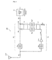
- Fig. 1 shows the structure of a communication apparatus having a transceiving filter device according to a first embodiment.
- reference symbol ANT denotes an antenna of a base station
- a transceiving circuit 10 is a circuit that transmits and receives a communication signal in the base station.
- the components other than the antenna ANT and the transceiving circuit 10 form a transceiving filter device 100.
- the antenna ANT is connected to a first port #1 of the transceiving filter device 100, and the transceiving circuit 10 is connected to a second port #2 of the transceiving filter device 100.
- the transceiving filter device 100 and the antenna ANT are disposed on the tower top portion of the base station.
- Reference numerals Rx1 and Rx2 denote receiving filters having a bandpass characteristic that allows a receiving-frequency-band signal to pass and that stops a transmission-frequency-band signal.
- Reference symbol LNA denotes a low-noise amplification circuit.
- the two receiving filters Rx1 and Rx2 are disposed on the input and output sides of the amplification circuit LNA, respectively, and these components are placed in a first transmission path P1.
- Reference numeral Tx1 denotes a transmitting filter having a bandstop filter characteristic that allows a transmission-frequency-band signal to pass and that stops a receiving-frequency-band signal.
- the transmitting filter Tx1 is placed in a second transmission path P2.
- Reference numeral 11 denotes a coupled-line directional coupler.
- the directional coupler 11 couples a line between ports (1) and (3) thereof and a line between ports (2) and (4) thereof, and separates the ports (1) and (4) and the ports (3) and (2).
- the ports (2) and (4) of the directional coupler 11 are connected to the second port #2 and the transmitting filter Tx1, respectively.
- the port (1) is connected to the receiving filter Rx2.
- the port (3) terminates with a resistor R.
- an input signal from the port (1) of the directional coupler 11 is output to the ports (2) and (3).
- An input signal from the port (2) is output to the port (4). Therefore, a received signal from the antenna ANT passes through the receiving filter Rx1, and is then amplified by the amplification circuit LNA.
- the amplified signal passes through the receiving filter Rx2, and is then output to the second port #2 via the directional coupler 11.
- a transmission signal from the transceiving circuit 10 is input from the second port #2, passing through the transmitting filter Tx1 via the directional coupler 11, and is then output to the antenna ANT from the first port #1.
- the received signal output from the receiving filter Rx2 does not return to the second transmission path P2, and is not oscillated since positive feedback does not occur.
- Fig. 2 shows the structure of a communication apparatus having a transceiving filter device according to a second embodiment.
- 90° hybrid circuits 12 and 13 and receiving filters Rx2 and Rx2' are disposed at the connection between the first transmission path P1 and the second transmission path P2.
- hybrid circuits 12 and 13 are power-halving circuits having directivity in the signal transmission direction.
- the hybrid circuit 12 power-halves the received signal amplified by the amplification circuit LNA, and the hybrid circuit 13 outputs the received signal which has passed through the receiving filters Rx2 and Rx2' to the port #2. As described below, the received signal which has passed through the receiving filters Rx2 and Rx2' is not transmitted to the second transmission path P2.
- the receiving filters Rx2 and Rx2' disposed between the two 90° hybrid circuits 12 and 13 pass the receiving frequency band and stop the transmission frequency band. This prevents a transmission signal from entering the first transmission path P1 from the port #2.
- the structure of the other components is similar to that of the first embodiment.
- Fig. 3 shows the operation of the hybrid circuits 12 and 13.
- the lines at the four sides of each of the hybrid circuits 12 and 13 are represented by La, Lb, Lc, and Ld.
- the impedance of the lines Lc and Ld is Zo
- the impedance of the lines La and Lb is given by Zo/ ⁇ 2.
- Each line has an electrical length of one-quarter the wavelength of the transmission frequency. Therefore, the received signal input to the hybrid circuit 12 is power-halved into two opposite-phase signals, which are then input to the receiving filters Rx2 and Rx2', respectively.
- the two receiving filters Rx2 and Rx2' have substantially the same filter characteristic.
- the signals which have passed through the receiving filters Rx2 and Rx2' are phase-combined again by the hybrid circuit 13, and the result is transmitted to the port #2.
- the signals which are to be transmitted in the direction indicated by a broken line shown in Fig. 3 are combined in opposite phase, and are cancelled, so as not to be transmitted.
- the receiving filters Rx2 and Rx2' inserted between the two hybrid circuits 12 and 13 allow received signals, once branched, to be superposed in phase in the direction of the port #2 and to be superposed in opposite phase in the direction of the port #1 when they are combined again.
- the transmission signal input from the port #2 is input to the receiving filters Rx2 and Rx2' via the hybrid circuit 13, but this signal is stopped by the receiving filters Rx2 and Rx2' and is not input to the output side of the amplification circuit LNA shown in Fig. 2. Therefore, the amplification circuit LNA is not damaged and does not suffer from distortion such as intermodulation distortion.
- the received signal is transmitted with directivity to the port #2, resulting in no positive feedback of the received signal by the loop of the two transmission paths P1 and P2 shown in Fig. 2.
- Fig. 4 is a block diagram of the transceiving filter device.
- the basic structure of this transceiving filter device is the same as that of the transceiving filter device shown in Fig. 2.
- one of two 90° hybrid circuits that is, a 90° hybrid circuit 14 has a two-stage structure.
- the structure of the remaining components is similar to that shown in Fig. 2.
- Fig. 5 shows the structure of the hybrid circuit 14 portion.
- Each of lines L1 through L7 has an electrical length of one-quarter the wavelength of the transmission frequency.
- the impedances of these lines are as follows:
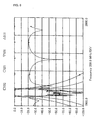
- Fig. 6 shows characteristics of the two-stage hybrid circuit, in which the y-axis designates the transmission loss or the reflection loss, expressed in dB.
- the center frequency of the receiving frequency band is 1950 MHz, and the transmission frequency band is outside the range of 1920 MHz to 1980 MHz.
- the curve indicated by circles represents the transmission characteristic (S21 characteristic) in the direction of ports (1) ⁇ (2)
- the curve indicated by rectangles represents the transmission characteristic (S32 characteristic) in the direction of ports (2) ⁇ (3) of the hybrid circuit
- the curve indicated by downward-pointing triangles represents the transmission characteristic (S31 characteristic) in the (1) ⁇ (3) direction
- the curve indicated by upward-pointing triangles represents the reflection characteristic (S11 characteristic) of the port (1).
- the S32 characteristic maintains substantially 0 dB across a broad frequency band including the transmission frequency band, thus achieving a low insertion loss characteristic. Therefore, the transmission signal is transmitted from the port (2) to the port (3) with low losses.
- the S21 characteristic also exhibits substantially 0 dB in the receiving frequency band, thus achieving a low insertion loss characteristic. Therefore, the received signal is transmitted from the port (1) to the port (2) with low losses.
- a 90° hybrid circuit with three or more stages may also be used.
- Fig. 7 shows the structure of a communication apparatus having a transceiving filter device according to a fourth embodiment.
- a circulator 15 is disposed at the connection between the first transmission path P1 and the second transmission path P2.
- the circulator 15 is a circulator with a forward direction in the direction of ports (1) ⁇ (2) and (2) ⁇ (3).
- the received signal passing through the transmission path P1 is input to the port (1) of the circulator 15, and is transmitted to the port #2 from the port (2).
- the transmission signal input from the port #2 to the port (2) of the circulator 15 is output from the port (3), and is transmitted to the second transmission path P2.
- Such a 2-GHz-band circulator can be manufactured at low cost, and the cost of the overall transceiving filter device can be reduced.
- a transceiving filter device including a first transmission path and a second transmission path between a first port connected to an antenna and a second port connected to a transceiving circuit
- the first transmission path including an amplification circuit that amplifies a received signal and a receiving filter that allows a receiving-frequency-band signal to pass
- the second transmission path allowing a transmission signal to pass, positive feedback in which the received signal returns to the input side of the first transmission path via the second transmission path does not occur, thus preventing oscillation. Therefore, it is not necessary to increase the stop bandwidth (receiving frequency bandwidth) of the transmitting filter in the second transmission path or to reduce the pass bandwidth of the first transmission path for the received signal. As a result, the insertion loss, noise figure, and group delay characteristics of the transmission signal or the received signal can be improved.
- a circuit having directivity in which the received signal amplified by the amplification circuit is transmitted to the second port and the transmission signal input from the second port is transmitted to the second transmission path is disposed at the output side of the amplification circuit of the first transmission path and at a connection between the first transmission path and the second transmission path. Therefore, the received signal passing through the first transmission path is transmitted to the second port, and is not transmitted to the second transmission path. Positive feedback of the received signal does not occur, thus ensuring that oscillation is prevented.
- the circuit having directivity is formed of a coupled-line directional coupler and a termination resistor, thus preventing oscillation with the simple circuit structure.
- the circuit having directivity is formed of a 90° hybrid circuit and a termination resistor, thus preventing oscillation with the simple circuit structure.
- the 90° hybrid circuit has a plurality of stages, thus increasing the pass bandwidth for the transmission signal.
- the circuit having directivity is formed of a circulator, thus reducing the cost.
- the transceiving filter device is disposed between a duplexer antenna and a transceiving circuit, thus improving the insertion loss, noise figure, and group delay characteristics of the transmission signal or received signal. Therefore, a high-communication-performance communication apparatus capable of high-speed transmission with a low data error rate can be realized.
- a transceiving filter device provides improvement in insertion loss, noise figure, and group delay characteristics of a transmission signal or received signal, and is suitable for a communication apparatus for use in, for example, microwave-band or millimeter-wave-band radio communication or electromagnetic wave transmission and reception.
Landscapes
- Engineering & Computer Science (AREA)
- Computer Networks & Wireless Communication (AREA)
- Signal Processing (AREA)
- Transceivers (AREA)
- Filters And Equalizers (AREA)
Abstract
Description
Claims (7)
- A transceiving filter device comprising a first transmission path and a second transmission path between a first port connected to an antenna and a second port connected to a transceiving circuit, the first transmission path including an amplification circuit that amplifies a received signal and a receiving filter that allows a receiving-frequency-band signal to pass, the second transmission path allowing a transmission signal to pass, wherein an element that prevents positive feedback of the received signal in a loop formed of the first transmission path and the second transmission path is disposed in the loop.
- A transceiving filter device according to Claim 1, wherein the second transmission path includes a transmitting filter that passes the transmission signal and that stops a receiving-frequency-band signal, and a circuit having directivity in which the received signal amplified by the amplification circuit is transmitted to the second port and the transmission signal input from the second port is transmitted to the second transmission path is disposed at the output side of the amplification circuit of the first transmission path and at a connection between the first transmission path and the second transmission path, said circuit serving as the element that prevents positive feedback.
- A transceiving filter device according to Claim 2, wherein the circuit having directivity comprises a coupled-line directional coupler that transmits the received signal amplified by the amplification circuit to the second port and that transmits the transmission signal input from the second port to the second transmission path, and a termination resistor that terminates a portion of the received signal amplified by the amplification circuit.
- A transceiving filter device according to Claim 2, wherein the circuit having directivity comprises a 90° hybrid circuit that transmits the received signal amplified by the amplification circuit to the second port and that transmits the transmission signal input from the second port to the second transmission path, and a termination resistor that terminates a portion of the received signal amplified by the amplification circuit.
- A transceiving filter device according to Claim 4, wherein the 90° hybrid circuit has a plurality of stages.
- A transceiving filter device according to Claim 2, wherein the circuit having directivity comprises a circulator that transmits the received signal amplified by the amplification circuit to the second port and that transmits the transmission signal input from the second port to the second transmission path.
- A communication apparatus comprising an antenna connected to the first port of the transceiving filter device according to any one of Claims 1 through 6, and a transceiving circuit connected to the second port of the transceiving filter device.
Applications Claiming Priority (3)
| Application Number | Priority Date | Filing Date | Title |
|---|---|---|---|
| JP2002269121 | 2002-09-13 | ||
| JP2002269121A JP3937986B2 (en) | 2002-09-13 | 2002-09-13 | Transmission / reception filter device and communication device |
| PCT/JP2003/010283 WO2004025850A1 (en) | 2002-09-13 | 2003-08-13 | Transmitting/receiving filter device and communication device |
Publications (2)
| Publication Number | Publication Date |
|---|---|
| EP1533911A1 true EP1533911A1 (en) | 2005-05-25 |
| EP1533911A4 EP1533911A4 (en) | 2010-03-31 |
Family
ID=31986805
Family Applications (1)
| Application Number | Title | Priority Date | Filing Date |
|---|---|---|---|
| EP03788698A Withdrawn EP1533911A4 (en) | 2002-09-13 | 2003-08-13 | Transmitting/receiving filter device and communication device |
Country Status (7)
| Country | Link |
|---|---|
| US (1) | US7116966B2 (en) |
| EP (1) | EP1533911A4 (en) |
| JP (1) | JP3937986B2 (en) |
| KR (1) | KR100644536B1 (en) |
| CN (1) | CN1557054A (en) |
| AU (1) | AU2003255019A1 (en) |
| WO (1) | WO2004025850A1 (en) |
Families Citing this family (17)
| Publication number | Priority date | Publication date | Assignee | Title |
|---|---|---|---|---|
| JP2006222551A (en) * | 2005-02-08 | 2006-08-24 | Fujitsu Media Device Kk | Electronic circuit device |
| JP5740833B2 (en) * | 2010-04-20 | 2015-07-01 | ソニー株式会社 | Communication apparatus and communication system |
| US8570106B2 (en) * | 2011-05-13 | 2013-10-29 | Qualcomm, Incorporated | Positive feedback common gate low noise amplifier |
| CN105103462A (en) | 2012-12-11 | 2015-11-25 | 南加利福尼亚大学 | Passive leakage cancellation networks for duplexers and coexisting wireless communication systems |
| WO2015089091A1 (en) | 2013-12-10 | 2015-06-18 | University Of Southern California | Enhancing isolation and impedance matching in hybrid-based cancellation networks and duplexers |
| WO2015123668A1 (en) | 2014-02-14 | 2015-08-20 | University Of Southern California | Hybrid-based cancellation in presence of antenna mismatch |
| WO2015123586A1 (en) | 2014-02-14 | 2015-08-20 | University Of Southern California | Reflection and hybrid reflection filters |
| US9871543B2 (en) * | 2014-02-19 | 2018-01-16 | University Of Southern California | Miniature acoustic resonator-based filters and duplexers with cancellation methodology |
| US9912326B2 (en) | 2015-09-08 | 2018-03-06 | Abtum Inc. | Method for tuning feed-forward canceller |
| US9762416B2 (en) | 2015-09-08 | 2017-09-12 | Abtum Inc. | Reflection coefficient reader |
| US10581650B2 (en) | 2015-09-08 | 2020-03-03 | Qorvo Us, Inc. | Enhancing isolation in radio frequency multiplexers |
| US9866201B2 (en) | 2015-09-08 | 2018-01-09 | Abtum Inc. | All-acoustic duplexers using directional couplers |
| US9755668B2 (en) | 2015-09-30 | 2017-09-05 | Abtum Inc. | Radio frequency complex reflection coefficient reader |
| US10038458B2 (en) | 2015-10-06 | 2018-07-31 | Abtum Inc. | Reflection-based radio-frequency multiplexers |
| KR102527018B1 (en) | 2015-10-12 | 2023-04-27 | 압툼 인크. | Hybrid coupler based radio frequency multiplexer |
| KR102419926B1 (en) | 2016-09-21 | 2022-07-11 | 코르보 유에스, 인크. | Improved Isolation of Hybrid-Based Radio Frequency Duplexers and Multiplexers |
| KR102597059B1 (en) | 2016-10-13 | 2023-11-02 | 한국전자통신연구원 | Microwave filter system including a feedback structure |
Family Cites Families (9)
| Publication number | Priority date | Publication date | Assignee | Title |
|---|---|---|---|---|
| DE4238282A1 (en) | 1992-11-13 | 1994-05-19 | Philips Patentverwaltung | Radio |
| JP3248785B2 (en) * | 1992-12-14 | 2002-01-21 | 富士通株式会社 | Wireless transmission / reception device capable of loopback test |
| GB2297459A (en) * | 1995-01-26 | 1996-07-31 | Airtech Ltd | A mast head device |
| JP3278377B2 (en) | 1997-05-13 | 2002-04-30 | 三菱電機株式会社 | Microwave transceiver module |
| JP2001358605A (en) | 2000-06-13 | 2001-12-26 | Matsushita Electric Ind Co Ltd | Wireless communication device and wireless communication method |
| US6885855B1 (en) | 2000-10-10 | 2005-04-26 | Adc Telecommunications, Inc. | High frequency amplification circuit |
| JP2002124901A (en) | 2000-10-17 | 2002-04-26 | Nagano Japan Radio Co | Wireless device |
| DE60034130D1 (en) * | 2000-11-22 | 2007-05-10 | Ericsson Telefon Ab L M | RF antenna switch |
| FI20002881A7 (en) * | 2000-12-29 | 2002-06-30 | Nokia Corp | Arrangement and method for reducing radio transmitter losses |
-
2002
- 2002-09-13 JP JP2002269121A patent/JP3937986B2/en not_active Expired - Lifetime
-
2003
- 2003-08-13 AU AU2003255019A patent/AU2003255019A1/en not_active Abandoned
- 2003-08-13 KR KR1020047013526A patent/KR100644536B1/en not_active Expired - Fee Related
- 2003-08-13 WO PCT/JP2003/010283 patent/WO2004025850A1/en not_active Ceased
- 2003-08-13 EP EP03788698A patent/EP1533911A4/en not_active Withdrawn
- 2003-08-13 US US10/487,880 patent/US7116966B2/en not_active Expired - Lifetime
- 2003-08-13 CN CNA038010313A patent/CN1557054A/en active Pending
Also Published As
| Publication number | Publication date |
|---|---|
| US20040242164A1 (en) | 2004-12-02 |
| AU2003255019A1 (en) | 2004-04-30 |
| CN1557054A (en) | 2004-12-22 |
| EP1533911A4 (en) | 2010-03-31 |
| WO2004025850A1 (en) | 2004-03-25 |
| JP2004112106A (en) | 2004-04-08 |
| JP3937986B2 (en) | 2007-06-27 |
| KR20040089687A (en) | 2004-10-21 |
| US7116966B2 (en) | 2006-10-03 |
| KR100644536B1 (en) | 2006-11-10 |
Similar Documents
| Publication | Publication Date | Title |
|---|---|---|
| US7116966B2 (en) | Transmitting/receiving filter device and communication device | |
| EP3210306B1 (en) | Radio frequency multiplexer | |
| US12301270B2 (en) | Radio-frequency front-end circuit and communication apparatus | |
| US7142884B2 (en) | Combined front-end circuit for wireless transmission systems | |
| US10756408B2 (en) | Directional coupler, high-frequency front-end module, and communication device | |
| US6512427B2 (en) | Spurious signal reduction circuit | |
| CN103546189B (en) | Radio frequency front-end circuit and system | |
| US7236519B2 (en) | Transceiving filter and communication device | |
| KR102246038B1 (en) | Communication module | |
| JP3970735B2 (en) | Composite filter, antenna duplexer, and communication device | |
| JP2004200853A (en) | High frequency circuit device | |
| EP3701629B1 (en) | Radio frequency front end for wireless communication | |
| KR100906776B1 (en) | IS filter module with switch LAN | |
| CN100388825C (en) | A signal combination device and base station common antenna feeder system realized by using it | |
| KR100962252B1 (en) | Filter module suppressing interference signal | |
| CN114362787B (en) | Antenna connection circuits, devices and unmanned equipment | |
| JPH08195695A (en) | Transmitter-receiver with shared antenna | |
| US20230216167A1 (en) | Filter topology for improved matching | |
| JP2009060511A (en) | Communication device | |
| JP2855989B2 (en) | High frequency signal amplifier circuit | |
| KR20210081874A (en) | Front end module | |
| EP0977301A1 (en) | Coupler and mobile phone | |
| KR20010103453A (en) | Feu filter module apparatus of base station inthe wll system | |
| KR20000050621A (en) | Gain control possility amplification circuit in the mobile communication terminal | |
| KR20090090966A (en) | Wii repeater suppresses interference signals |
Legal Events
| Date | Code | Title | Description |
|---|---|---|---|
| PUAI | Public reference made under article 153(3) epc to a published international application that has entered the european phase |
Free format text: ORIGINAL CODE: 0009012 |
|
| 17P | Request for examination filed |
Effective date: 20040210 |
|
| AK | Designated contracting states |
Kind code of ref document: A1 Designated state(s): AT BE BG CH CY CZ DE DK EE ES FI FR GB GR HU IE IT LI LU MC NL PT RO SE SI SK TR |
|
| AX | Request for extension of the european patent |
Extension state: AL LT LV MK |
|
| DAX | Request for extension of the european patent (deleted) | ||
| RAP1 | Party data changed (applicant data changed or rights of an application transferred) |
Owner name: MURATA MANUFACTURING CO., LTD. |
|
| A4 | Supplementary search report drawn up and despatched |
Effective date: 20100302 |
|
| STAA | Information on the status of an ep patent application or granted ep patent |
Free format text: STATUS: THE APPLICATION IS DEEMED TO BE WITHDRAWN |
|
| 18D | Application deemed to be withdrawn |
Effective date: 20100601 |