EP1533878B1 - Verfahren und System zur Vorfertigung von elektrischen Installationen - Google Patents
Verfahren und System zur Vorfertigung von elektrischen Installationen Download PDFInfo
- Publication number
- EP1533878B1 EP1533878B1 EP04292602A EP04292602A EP1533878B1 EP 1533878 B1 EP1533878 B1 EP 1533878B1 EP 04292602 A EP04292602 A EP 04292602A EP 04292602 A EP04292602 A EP 04292602A EP 1533878 B1 EP1533878 B1 EP 1533878B1
- Authority
- EP
- European Patent Office
- Prior art keywords
- sheath
- box
- sheaths
- prefabricating
- bowl
- Prior art date
- Legal status (The legal status is an assumption and is not a legal conclusion. Google has not performed a legal analysis and makes no representation as to the accuracy of the status listed.)
- Expired - Lifetime
Links
- 238000000034 method Methods 0.000 title claims abstract description 21
- 238000010616 electrical installation Methods 0.000 title description 21
- 238000009434 installation Methods 0.000 claims abstract description 16
- 238000009417 prefabrication Methods 0.000 claims description 28
- 238000004804 winding Methods 0.000 claims description 14
- 238000005520 cutting process Methods 0.000 claims description 12
- 238000010586 diagram Methods 0.000 claims description 7
- 230000000295 complement effect Effects 0.000 claims description 3
- WABPQHHGFIMREM-UHFFFAOYSA-N lead(0) Chemical compound [Pb] WABPQHHGFIMREM-UHFFFAOYSA-N 0.000 claims description 3
- 230000035515 penetration Effects 0.000 claims description 3
- 238000005096 rolling process Methods 0.000 claims 2
- 238000009966 trimming Methods 0.000 claims 1
- 238000005553 drilling Methods 0.000 abstract description 11
- 238000004519 manufacturing process Methods 0.000 abstract description 6
- 238000005452 bending Methods 0.000 description 7
- 238000009987 spinning Methods 0.000 description 6
- 210000002105 tongue Anatomy 0.000 description 4
- 241000212322 Levisticum officinale Species 0.000 description 3
- 239000001645 levisticum officinale Substances 0.000 description 3
- 241000239290 Araneae Species 0.000 description 2
- 241000238413 Octopus Species 0.000 description 2
- 241001417494 Sciaenidae Species 0.000 description 2
- 230000008901 benefit Effects 0.000 description 2
- 241000863032 Trieres Species 0.000 description 1
- 239000006096 absorbing agent Substances 0.000 description 1
- 230000000903 blocking effect Effects 0.000 description 1
- 239000003086 colorant Substances 0.000 description 1
- 230000036461 convulsion Effects 0.000 description 1
- 238000013016 damping Methods 0.000 description 1
- 238000004080 punching Methods 0.000 description 1
- 230000035939 shock Effects 0.000 description 1
Images


Classifications
-
- H—ELECTRICITY
- H02—GENERATION; CONVERSION OR DISTRIBUTION OF ELECTRIC POWER
- H02G—INSTALLATION OF ELECTRIC CABLES OR LINES, OR OF COMBINED OPTICAL AND ELECTRIC CABLES OR LINES
- H02G3/00—Installations of electric cables or lines or protective tubing therefor in or on buildings, equivalent structures or vehicles
-
- H—ELECTRICITY
- H02—GENERATION; CONVERSION OR DISTRIBUTION OF ELECTRIC POWER
- H02G—INSTALLATION OF ELECTRIC CABLES OR LINES, OR OF COMBINED OPTICAL AND ELECTRIC CABLES OR LINES
- H02G11/00—Arrangements of electric cables or lines between relatively-movable parts
- H02G11/02—Arrangements of electric cables or lines between relatively-movable parts using take-up reel or drum
Definitions
- the method and system for prefabrication of electrical installations according to the invention are for the purpose of prefabrication of electrical circuits intended to be installed in residential buildings, industrial buildings and commercial buildings.
- the purpose of the present invention is to overcome certain disadvantages of the prior art by proposing a prefabrication system for electrical installations, which makes it possible to greatly reduce the prefabrication time and especially to reduce the risks of workshop errors to almost zero. .
- a system for prefabrication of electrical installations characterized in that it comprises a bending machine containing a drum reel or coiling bowl provided with means for holding at least one branch box, means for transfer of a sheath equipped with conducting wire, which make it possible to present this equipped sheath in front of a hole made in the box and designed to snap the sheath therein, as well as means for rotating the reel drum or the coiling bowl after snapping the sheath onto the junction box to cause the sheath to curl in the drum or bowl.
- the holding means of the junction box are arranged on the flanges of the drum drum or around the center of the bobbing bowl and consist of a tube at the free end of which are formed two shaped housing each housing housing a tongue of complementary shape formed at the base of the junction box, said box then being fixed to the tube by rotation in the direction of coiling, this rotation causing the penetration of the tongues in a slot of the tube, which is perpendicular to said tube, for locking the box in translation, and said slot being provided with stops to block the rotating box.
- the coater-monteuse comprises at least one groove disposed on the flanges of the drum winder or the walls of the coiling bowl to allow to pass means to bind the equipped rolled sleeves at the end of prefabrication.
- the prefabrication system comprises a piercing system of the junction box.
- the prefabrication system comprises a spinner for threading determined threads in a specific sheath.
- the prefabrication system comprises a sheath selection system comprising transfer means for placing the selected sheath in the spinning axis of the spinning machine and locking means for jacks to block the sheath in position.
- the sheath selection system is of the barrel or drawer type.
- the prefabrication system comprises a threader consisting of flexible capillary tubes, which leads the son from the wire distributors to the input of the spinner.
- the prefabrication system comprises a sheath cutter device disposed before the sheath selection system and a wire cutting / stripping device disposed at the outlet of the threader.
- Another object of the invention is to provide a method of prefabrication of electrical installations.
- the step of winding the equipped sheaths is followed by a step of bonding said wound sheaths.
- the box is removed from the reel drum or the coiling bowl, then a second box is fixed in place of the first box in the drum reel or lovage bowl and a fitted sheath snapped onto the first box is connected to the second box being snapped onto a suitable hole of the second box, then a new sheath is equipped and snapped onto the second box and coiled.
- the selection of the sheath is performed by a selection system
- the introduction of wire into the sheath is performed by a spinner
- the attachment of the sheath to the box is performed by a sheath transfer system, these three systems being controlled via a software module.
- the attachment of the box on the bower-editor is preceded by a step of drilling holes in the box through a drilling system, each of the holes made being adapted to receive a sheath equipped with conductive wire.
- the prefabrication method comprises a step of sorting, by the software module, sheaths and threads to be threaded into each sheath, in an order of assembly on the junction box, this order of assembly being determined according to of parameters or characteristics of the sheaths and threads to be slipped into the sheaths.
- each of the equipped sheaths is directly fixed to the junction box at the exit of the spinner and coiled as it exits the reel drum or the coiling bowl after about 1 meter of exit, none of the sheaths not crossing each other.
- the parameters and characteristics of the sheaths and son taken into account during the sorting step include the diameter and the length of the sheath, the color, the section and the over-length of the threads to be threaded into the sheath, as well as the hole of the box in which snap the equipped sheath, these parameters and characteristics being stored in a file that can be used by the software module.
- each sheath is cut by a cutting device located before the sheath selection system and each wire is cut and stripped by a cutting / stripping device at the outlet of the threader.
- the system for prefabrication of electrical installations according to the invention makes it possible to produce electrical installations consisting of one or more branch boxes (2) connected together by sheaths (1). equipped with lead wire and on which are snapped one or more sleeves (1) also equipped with wire.
- the system for prefabrication of electrical installations comprises a drilling system (14) of the junction boxes (2), display means (15), computer means, a threader (9), a device for cutting / stripping (12) of the wires, a sheath selection system (7), a sheath cutting device (17), a spinner (11), a bending machine and a transfer system (13) of the equipped sheath (1) in the bending machine.
- the threader (9) causes the threads to thread into the sheaths (1) selected by the selection system (7) from thread distributors (10) to the spinner (11).
- Wire distributors are wire coils of different diameters and colors. In general, only about twenty different coils of wire to prefabricate an electrical installation.
- the threader (9) consists of flexible capillary tubes (8) each guiding a thread. This flexibility makes it possible to cushion the jerk with the rotation of the unwinders of thread.
- the mounting of the capillary tubes (8) with a cantilever length serves as a shock absorber at the start of the son unwinders.
- the system may be made by a series of perforated plates but it will no longer fulfill the damping function.
- the cutting / stripping device (12), disposed at the outlet of the threader (9), is used to strip and cut to the desired length the threads entering the spinner (11).
- Each sheath (1) to be equipped is selected by the sheath selection system (7) before spinning.
- the latter consists of a slide device (7) or barrel, two cylinders each ensuring the blocking of a sheath, and a transfer cylinder for placing the right sheath in the spinning axis.
- the spinner (11) allows to introduce the selected son in the sheath (1) selected.
- the sheath (1) equipped is then put in place by snapping on the box (2) fixed on the coater-monteuse by the transfer system (13) sheath.
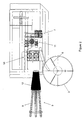
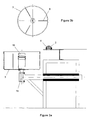
- the coater-assembler represented in particular in FIG. 3a, comprises a winding drum or a coiling bowl (3) on which is fixed a bypass box (2) previously pierced by the drilling system (14) with holes ( 4) adapted to snap fitted sheaths (1).
- the box Bypass (2) is fixed on a box support, for example a tube, located on the flanges of the drum drum or around the center of the cowl.
- the fastening system (16) of the junction box (2) on this support is, for example, but without limitation, a machined tip at the free end of the tube, as shown in Figure 3a.
- This fixing system can be fixed or interchangeable and in any case adapted to the junction box (2).
- the fastening system (16) of the junction box (2) consists of a tube at the free end of which are formed two ear-shaped housings, each of housings housing a tongue of complementary shape formed at the base of the junction box, said box then being fixed to the tube by rotation in the direction of coiling, this rotation causing the penetration of the tongues in a slot of the tube, which is perpendicular to said tube, for locking the box in translation, and said slot being provided with stops to block the rotating box.
- the coater can be used in automatic manufacturing as well as in manual production. However, in the latter case, it is not getting any benefit from the system.
- the mower-editor also comprises a motorized system (18) for rotating the drum drum or coiling bowl (3) around the axis of symmetry of the latter to wind the sheaths (1) equipped around the box bypass (2).
- the equipped sheaths (1) are directly fixed by snapping on the junction box at the output of the spinner and coiled as they arrive in the loosening bowl by stopping after about 1 meter of output.
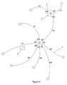
- the octopus-shaped electrical installation is thus realized, which may comprise one or more junction boxes (2), as shown in particular in FIG. 4.
- the equipped sheaths wound on the branch boxes (2) are attached by links (manual or automatic), which are inserted via grooves (6) formed in the flanges of the drum drum or in the walls of the bowl coiling (3).
- the computer means also include a drawing software (eg Autocad).
- a user of the method and of the prefabrication system according to the invention enters into memory in the computer means a diagram of the electrical installation to be produced, as shown in FIG. 4.
- the diagram represents each junction box (2), identified by FIG. letters (A, B), and the characteristics (5) of each sheath leaving said box (diameter and length of the sheath, number, section and over-length of the wires, hole of the box on which to snap the fitted sheath) .
- the over-wire length connects the end of the sheath to the various outlets, switches or other housings present in the apartment or other where the electrical installation will be placed. None of the sheaths cross each other.
- the identification of the threads is done by a color code.
- FIG. 5 An example of this text file is shown in Figure 5. It consists of several columns. The first column contains the list of the holes, marked by numbers, of each box, indicated by a letter. The second column indicates the length of the sheath to snap into each hole listed in the first column. The third column indicates the over-length of wire protruding from each sheath. The fourth column indicates whether or not there is a reservation box. The fifth column indicates the diameter of each sheath, for example 20 mm. The sixth and seventh columns indicate the color code of the son of different determined sections, for example but not limited to 2.5 mm and 1.5 mm respectively, to slip into the sheath having the characteristics indicated on the same line in the previous columns.
- the text file is processed by a specific program, called software module, which sorts the ducts and wires in the order of assembly of the electrical installation and sends this list to the on-board PLC on the prefabrication system according to the invention. who stores it. At the time of prefabrication of the electrical installation, the ducts will be selected, equipped with wire, and snapped on the box in the order of assembly of the electrical installation.
- software module which sorts the ducts and wires in the order of assembly of the electrical installation and sends this list to the on-board PLC on the prefabrication system according to the invention. who stores it.
- the ducts will be selected, equipped with wire, and snapped on the box in the order of assembly of the electrical installation.
- the sorted text files are stored in queue on the prefabrication system according to the invention and are executed at the request by the operator.
- Display means (15), for example a touch screen, is connected to the controller. These display means display in order the various steps to be performed by the operator.
- the display means (15) first display the drilling characteristics of the holes (4) to be made on the junction box (2) by means of the piercing system (14): the number, the location and the diameter of the holes.
- the piercing system (14) also having a punching function for marking the numerical markings of the holes on the junction box (2)
- the display means (15) also display the numerical markings to punch in the box, by means of of the piercing system (14).
- the display means display the characteristics (diameter, length) of the sheaths (1) to be selected by the selection system (7) and the characteristics (over-length, diameter, color code ) threads to be pulled by the threader (9) to the spinner (11) and threaded into the good sheath (1) by the spinner (11).
- the display means display the mark of the hole (4) of the junction box (2) on which said sheath (1) is to be snapped. The equipped sheath is transferred to the coater-assembler, either manually or by the transfer system (13).
- the operator realizes the junction box, assisted by the controller that controls the various elements of the prefabrication system according to the invention.
- the selection and placement of the sheath of good diameter in the axis of the spinner (11) is done automatically by the sheath selection system (7) after reading the characteristics of the sheath (1). ).
- the stop (automatic or pedal foot) after one meter of sheath extracted to snap on the junction box (2) allows snapping.
- the drilling indications can be made during spinning.
- This manufacturing method according to the invention provides in practice less than 0.01% error or about one error per 100 dwellings.
- the display means (15) is also provided with a manual control page of the operations by keypad and matching functions. The choice of startup pages is done through the menu.
- the box A will be equipped first. It is first pierced by the drilling system, holes A1 to A7 at the planned locations, and then fixed in the coiler-editor.
- the sheath selection system (7) selects the sheath G1, which is cut to the correct length by the sheath cutter (17), taking into account the parameters (5) of the sheath, and then places said sheath G1. in the axis of the spinner (11).
- the threads to be threaded into the sheath G1 are selected (section, color), taking into account the parameters (5) of the threads, by the operator or by a drawer or barrel selection system of the same type as that used to select sheaths.
- the threads are then pulled by the threader (9), cut and stripped by the cutting / stripping device (12) of yarn, also taking into account the parameters (5) son.
- the threads are then threaded into the sheath G1 by the spinner (11), then the sheath G1 equipped with the conductive threads is transferred by the sheath transfer system (13) into the bending machine where it is snapped onto the hole A1 of the spool. box A.
- the sheath G1 is then coiled around the box.
- the sheaths G2 to G7 are then selected, equipped with suitable son, snapped onto the box A on the adapted holes and coiled in the same way as the sheath G1.
- the sheaths G1 to G7 are then attached by liures passed through the grooves (6) of the drum drum or the bowl (3) and box A is removed from the boring machine.
- Box B which was drilled while box A is being fitted, is attached to the bending machine instead of box A.
- Sheath G2, which is connected to box A, is snapped into place first. on hole B2 of box B, then coiled.
- the sheaths G'1 and G'3 are then selected, equipped with suitable son, snapped onto the box B on the adapted holes and coiled in the same way as the sheath G1 on the box A.
- the sheaths G'1, G2 and G'3 are also attached by links at the end of prefabrication.
- the prefabricated electrical installation is ready for delivery and installation in an apartment or other.
Landscapes
- Engineering & Computer Science (AREA)
- Architecture (AREA)
- Civil Engineering (AREA)
- Structural Engineering (AREA)
- Storage Of Web-Like Or Filamentary Materials (AREA)
- Wire Processing (AREA)
- Flow Control (AREA)
- Manufacturing Of Electrical Connectors (AREA)
- Manufacture Of Tobacco Products (AREA)
Claims (19)
- System zur Fertigung von elektrischen Installationen, dadurch gekennzeichnet, dass dieses eine Wickel- und Montagevorrichtung umfasst, welche eine Trommel zum Aufwickeln oder einen Wickelrotor (3) beinhaltet, der mit Haltevorrichtungen (16) für mindestens eine Verteilerdose (2) vorgesehen ist, sowie Transfermittel (13) für eine Isolierhülle (1), die einen Leiterdraht enthält, so dass diese Isolierhülle (1) vor eine Öffnung (4) gebracht werden kann, die sich in der Dose (2) befindet und zum Einrasten der Isolierhülle (1) in dieser Öffnung vorgesehen ist, sowie Antriebsmittel (18) zum Drehen der Trommel oder des Wickelrotors nach dem Einrasten der Isolierhülle (1) in der Verteilerdose (2), wonach sich die Isolierhülle (1) in der Trommel oder dem Rotor (3) aufwickelt.
- System zur Fertigung von elektrischen Installationen nach Anspruch 1, dadurch gekennzeichnet, dass die Haltevorrichtungen (16) der Verteilerdose (2) auf den Scheiben der Aufwickeltrommel oder in der Nähe des Zentrums des Wickelrotors (3) angeordnet sind und aus einem Rohr gebildet sind, an dessen freiem Ende zwei ohrmuschelförmige Hohlstellen ausgebildet sind, wobei jede Hohlstelle einen Bremsschuh mit komplementärer Form an der Basis der Verteilerdose aufnimmt, wobei die Verteilerdose dann auf dem Rohr durch Drehen im Wickelsinn befestigt wird, wobei diese Drehung das Eindringen der Bremsschuhe In einen Schlitz des Rohres, der senkrecht auf das Rohr ausgebildet ist, bewirkt, um somit die Verteilerdose an einer Translation zu hindern, und wobei der Schlitz mit Endbegrenzern versehen ist, um die Verteilerdose gegen Rotation zu blockieren.
- System zur Fertigung von elektrischen Installationen nach Anspruch 1 oder 2, dadurch gekennzeichnet, dass die Wickel- und Montagevorrichtung mindestens eine Rille (6) umfasst, die an den Scheiben der Aufwickeltrommel oder an den Wänden des Wickelrotors (3) vorgesehen ist, um den Durchtritt der Verbindungsmittel der Isolierhüllen (1), die für die Fertigung vorgesehen sind, zu gestatten.
- System zur Fertigung von elektrischen Installationen nach einem der Ansprüche 1 bis 3, dadurch gekennzeichnet, dass es ein System zum Durchbohren (14) der Verteilerdose (2) umfasst.
- System zur Fertigung von elektrischen Installationen nach einem der Ansprüche 1 bis 4, dadurch gekennzeichnet, dass es eine Einfädelvorrichtung (11) beinhaltet, welche das Einfädeln von vorbestimmten Leiterdrähten in vorbestimmte Isolierhüllen (1) gestattet.
- System zur Fertigung von elektrischen Installationen nach Anspruch 5, dadurch gekennzeichnet, dass es ein System (7) zur Auswahl der Isollerhüllen (1) beinhaltet, welches Transfermittel umfasst, die es ermöglichen, die ausgewählte Isolierhülle (1) In den Einfädelkopf der Elnfädelvorrichtung (11) zu positionieren, und Befestigungsmittel mit Klemmhebeln, um die Isolierhülle in dieser Positon festzuhalten.
- System zur Fertigung von elektrischen Installationen nach Anspruch 6, dadurch gekennzeichnet, dass das System (7) zur Auswahl der Isolierhüllen (1) vom Typ her zylindrisch oder schubladenartig ist.
- System zur Fertigung von elektrischen Installationen nach einem der Ansprüche 1 bis 7, dadurch gekennzeichnet, dass es Folgendes umfasst:- Datenverarbeitungsmittel, die ein Softwaremodul beinhalten, das dafür konfiguriert ist, die Isolierhüllen (1) nach einer vorgegebenen Reihenfolge der Montage an die Verteilerdosen (2) auszuwählen, wobei die Softwarekonfiguration Parameter und Kenngrößen (5) der zu verwendenden Isolierhüllen und Leiterdrähte berücksichtigt;- Anzeigemittel (15), die es ermöglichen, die Hinweise für die Durchbohrung der Verteilerdosen (2) und die Montage der Isolierhüllen und Leiterdrähte, die eingefädelt werden sollen, in der vorgegebenen Reihenfolge anzuzeigen.
- System zur Fertigung von elektrischen Installationen nach einem der Ansprüche 1 bis 7, dadurch gekennzeichnet, dass es eine Elnfädelvorrichtung (9) beinhaltet, die aus dünnen Kapillarrohren (8) gebildet ist, die die Leiterdrähte von den Drähteverteilern (10) zum Kopf der Einfädelvorrichtung (11) führen.
- System zur Fertigung von elektrischen Installationen nach einem der Ansprüche 1 bis 7, dadurch gekennzeichnet, dass es eine Schneidevorrichtung für Isolierhüllen (1) beinhaltet, die vor dem System (7) zur Auswahl der Isolierhüllen angeordnet ist und eine Vorrichtung zum Schneiden und Abisolleren (12) der Leiterdrähte, die am Ausgang der Einfädelvorrichtung (9) vorgesehen ist.
- Verfahren zur Fertigung von elektrischen Installationen, praktisch umgesetzt mittels einer automatischen Wickel- und Montagevorrichtung, die eine Trommel zum Aufwickeln oder einen Wickelrotor (3) beinhaltet, sowie Haltevorrichtungen (16) für mindestens eine Verteilerdose (2) nach Anspruch 1, dadurch gekennzeichnet, dass das Verfahren Folgendes umfasst:- eine Etappe der Befestigung der Dose (2) auf der Wickel- und Montagevorrichtung unter Verwendung der Haltevorrichtnugen (16);- eine Etappe der Anzeige durch die Anzeigemittel (15) der Hinweise für die Durchbohrung der Dose (2) und für die Montage der Isolierhüllen und der Leiterdrähte, die eingefädelt werden sollen, in der vorgegebenen Reihenfolge;- eine Etappe der Auswahl der Isolierhülle (1), der Einführung der Leiterdrähte in die Isolierhülle (1) und der Befestigung dieser Isolierhülle durch Einrasten in eine Öffnung (4), erzeugt in der Dose und definiert in einem Schema;- eine Etappe des Umwickelns der vorgesehenen Isolierhülle (1) um die Dose (2) aus der Aufwickeltrommel oder dem Wickelrotor (3),- die vorherigen Etappen werden für jede Isolierhülle, die an der Dose montiert werden soll, gemäß einer vorgegebenen Reihenfolge der Montage wiederholt.
- Verfahren nach Anspruch 11, dadurch gekennzeichnet, dass nach der Etappe des Aufwickelns der vorgesehenen Isolierhüllen (1) eine Etappe der Verbindung der aufgewickelten Isolierhüllen folgt.
- Verfahren nach Anspruch 11, dadurch gekennzeichnet, dass nach dem Verbinden der Isolierhüllen (1) die Dose (2) aus der Aufwickeltrommel oder dem Wickelrotor (3) herausgenommen wird, danach eine zweite Dose im Wickelrotor (3) an Stelle der ersten befestigt wird und eine vorgesehene, auf der ersten Dose (2) eingerastete Isolierhülle mit der zweiten Dose verbunden wird, Indem sie in eine angepasste Öffnung (4) der zweiten Dose eingerastet wird, danach eine weitere Isolierhülle vorgesehen wird und in der zweiten Dose eingerastet und danach aufgewickelt wird.
- Verfahren nach einem der Ansprüche 11 bis 13, dadurch gekennzeichnet, dass der Befestigung der Dose (2) auf der Wickel- und Montagevorrichtung eine Etappe der Bohrung von Öffnungen (4) in der Dose mit Hilfe einer Bohrvorrichtung (14) vorausgeht, wobei jede Bohrung für die Aufnahme einer mit Leiterdraht ausgestatteten Isolierhülle (1) vorgesehen ist.
- Verfahren nach einem der Ansprüche 11 bis 14, dadurch gekennzeichnet, dass die Wahl der Isolierhülle (1) von einem Auswahlsystem (7) vorgenommen wird, das Einführen des Leiterdrahts in die Isolierhülle (1) von einer Einfädelvorrichtung (11) ausgeführt wird und die Befestigung der Isolierhülle (1) auf der Dose (2) von einem Transfersystem (13) der Isolierhüllen durchgeführt wird, wobei diese drei Systeme (7, 11, 13) mittels einem Softwaremodul gesteuert werden.
- Verfahren nach Anspruch 15, dadurch gekennzeichnet, dass dieses eine vom Softwaremodul vorgenommene Auswahletappe der Isolierhüllen und der Leiterdrähte umfasst, die in jede Isolierhülle (1) eingeführt werden sollen, sowie einer Montagereihenfolge auf der Verteilerdose (2), wobei diese Montagereihenfolge von den Parametern und Kenngrößen (5) der Isolierhüllen und der einzuführenden Leiterdrähte bestimmt ist.
- Verfahren nach Anspruch 15 oder 16, dadurch gekennzeichnet, dass jede der vorgesehenen Isolierhüllen (1) am Ausgang der Einfädelvorrichtung (11) direkt auf der Verteilerdose (2) befestigt wird und beim Heraustreten nach etwa einem Meter auf die Trommel oder den Wickelrotor (3) aufgewickelt wird, ohne dass sich die Isolierhüllen überkreuzen.
- Verfahren nach Anspruch 16 oder 17, dadurch gekennzeichnet, dass die Parameter und Kenngrößen (5) der Isolierhüllen und Leitungsdrähte, die in der Auswahletappe berücksichtigt werden, den Durchmesser und die Länge der Isolierhülle (1), die Farbe, den Querschnitt und den Längenüberschuss der Leitungsdrähte, die in die Isolierhüllen (1) eingeführt werden sollen, sowie die Öffnung (4) der Dose (2), in welche die vorgesehene Isolierhülle eingerastet wird, einschließen, wobei diese Parameter und Kenngrößen in einer Datei gespeichert werden, die von dem Softwaremodul gelesen werden kann.
- Verfahren nach einem der Ansprüche 16 bis 18, dadurch gekennzeichnet, dass jede Islolierhülle (1) von einer Schneidevorrichtung (17) geschnitten wird, die vor dem Auswahlsystem (7) der Isolierhüllen angeordnet ist, und jeder Leitungsdraht von einer Schneide- und Abisollervorrichtung (12) beim Ausgang aus der EInfädelvorrichtung (9) geschnitten und abisoliert wird.
Applications Claiming Priority (2)
| Application Number | Priority Date | Filing Date | Title |
|---|---|---|---|
| FR0313558 | 2003-11-19 | ||
| FR0313558A FR2862446B1 (fr) | 2003-11-19 | 2003-11-19 | Prefabrication des installations electriques par systeme automatique loveuse-monteuse automatique |
Publications (2)
| Publication Number | Publication Date |
|---|---|
| EP1533878A1 EP1533878A1 (de) | 2005-05-25 |
| EP1533878B1 true EP1533878B1 (de) | 2007-02-28 |
Family
ID=34430023
Family Applications (1)
| Application Number | Title | Priority Date | Filing Date |
|---|---|---|---|
| EP04292602A Expired - Lifetime EP1533878B1 (de) | 2003-11-19 | 2004-11-03 | Verfahren und System zur Vorfertigung von elektrischen Installationen |
Country Status (4)
| Country | Link |
|---|---|
| EP (1) | EP1533878B1 (de) |
| AT (1) | ATE355643T1 (de) |
| DE (1) | DE602004004981D1 (de) |
| FR (1) | FR2862446B1 (de) |
Family Cites Families (2)
| Publication number | Priority date | Publication date | Assignee | Title |
|---|---|---|---|---|
| FR2353978A1 (fr) * | 1976-06-04 | 1977-12-30 | Fabrelec | Installation electrique prefabriquee pour locaux d'habitation ou autres |
| FR2566593B1 (fr) * | 1984-06-25 | 1987-01-16 | Labeyrie Ets | Procede de planification d'un reseau electrique d'un batiment a usage d'habitation et installation electrique prefabriquee obtenue selon ce procede |
-
2003
- 2003-11-19 FR FR0313558A patent/FR2862446B1/fr not_active Expired - Fee Related
-
2004
- 2004-11-03 DE DE602004004981T patent/DE602004004981D1/de not_active Expired - Lifetime
- 2004-11-03 EP EP04292602A patent/EP1533878B1/de not_active Expired - Lifetime
- 2004-11-03 AT AT04292602T patent/ATE355643T1/de not_active IP Right Cessation
Also Published As
| Publication number | Publication date |
|---|---|
| ATE355643T1 (de) | 2006-03-15 |
| DE602004004981D1 (de) | 2007-04-12 |
| EP1533878A1 (de) | 2005-05-25 |
| FR2862446A1 (fr) | 2005-05-20 |
| FR2862446B1 (fr) | 2006-01-13 |
Similar Documents
| Publication | Publication Date | Title |
|---|---|---|
| EP0382605B1 (de) | Vorrichtung zur Darstellung eines Verdrahtungsstücks in einer Ebene | |
| KR940001957A (ko) | 스풀에 금속선을 권취하는 방법과 장치 | |
| EP1533878B1 (de) | Verfahren und System zur Vorfertigung von elektrischen Installationen | |
| FR2755259A1 (fr) | Procede de mise en correspondance d'un boitier de commande de groupe avec un boitier de commande et/ou un boitier d'action et/ou un boitier de mesure | |
| CN203405660U (zh) | 透镜装置及摄像装置 | |
| EP0454905B1 (de) | Verfahren zum Einlegen von schmelzgespleisten optischen Fibern in ein Gehäuse | |
| EP2222508B1 (de) | Verfahren für den entwurf einer elektroverdrahtung für ein fahrzeug und verfahren zur herstellung einer derartigen verdrahtung | |
| FR2773241A1 (fr) | Procede d'assistance a l'administration d'une application distribuee basee sur un fichier binaire de configuration dans un systeme informatique | |
| CA1182887A (fr) | Commande numerique de plusieurs machines-outils par un mini-ordinateur | |
| CN101295904A (zh) | 用于转子的绕线机和生产转子的方法 | |
| BE569903A (de) | ||
| EP0942304B1 (de) | Verseilvorrichtung für ein faseroptisches Band | |
| EP1514147B1 (de) | Verfahren zur herstellung eines optischen kabels und diesbezügliche maschine | |
| JP2012160433A (ja) | ワイヤーハーネス布線治具、分岐ワイヤーハーネスの製造方法及びワイヤーハーネス分岐構造 | |
| EP0728117B1 (de) | Verfahren zur versetzten anordnung der lagen einer wicklung | |
| CN210339886U (zh) | 便于固定的漆包线生产用收线装置 | |
| EP0451195A1 (de) | Ärmelführer aus optischen fasern. | |
| JP3326066B2 (ja) | 組電線用素線の印字方法及び測長・印字装置 | |
| DE3107831C2 (de) | Wickelvorrichtung zur Herstellung elektrisch leitender Verbindungen | |
| DE3424209C1 (de) | Vorrichtung zum mehrlagigen SZ-Verseilen von Adern für nachrichtentechnische Kabel | |
| FR2668633A1 (fr) | Dispositif d'identification de cable electrique et procedes d'obtention s'y rapportant. | |
| FR2586406A1 (fr) | Appareil de commande de machine de bobinage et machine le comportant. | |
| JP2006023451A (ja) | 光ファイバトレイ及びそのトレイを用いた光ファイバ余長処理方法 | |
| FR3125653A1 (fr) | boite à fil électrique | |
| JP5019631B2 (ja) | 光ファイバケーブル及び光ファイバケーブルの製造方法 |
Legal Events
| Date | Code | Title | Description |
|---|---|---|---|
| PUAI | Public reference made under article 153(3) epc to a published international application that has entered the european phase |
Free format text: ORIGINAL CODE: 0009012 |
|
| AK | Designated contracting states |
Kind code of ref document: A1 Designated state(s): AT BE BG CH CY CZ DE DK EE ES FI FR GB GR HU IE IS IT LI LU MC NL PL PT RO SE SI SK TR |
|
| AX | Request for extension of the european patent |
Extension state: AL HR LT LV MK YU |
|
| 17P | Request for examination filed |
Effective date: 20051018 |
|
| GRAP | Despatch of communication of intention to grant a patent |
Free format text: ORIGINAL CODE: EPIDOSNIGR1 |
|
| AKX | Designation fees paid |
Designated state(s): AT BE BG CH CY CZ DE DK EE ES FI FR GB GR HU IE IS IT LI LU MC NL PL PT RO SE SI SK TR |
|
| GRAS | Grant fee paid |
Free format text: ORIGINAL CODE: EPIDOSNIGR3 |
|
| RAP1 | Party data changed (applicant data changed or rights of an application transferred) |
Owner name: CASSIER, HERVE |
|
| RIN1 | Information on inventor provided before grant (corrected) |
Inventor name: CASSIER, HERVE |
|
| GRAA | (expected) grant |
Free format text: ORIGINAL CODE: 0009210 |
|
| AK | Designated contracting states |
Kind code of ref document: B1 Designated state(s): AT BE BG CH CY CZ DE DK EE ES FI FR GB GR HU IE IS IT LI LU MC NL PL PT RO SE SI SK TR |
|
| PG25 | Lapsed in a contracting state [announced via postgrant information from national office to epo] |
Ref country code: IE Free format text: LAPSE BECAUSE OF FAILURE TO SUBMIT A TRANSLATION OF THE DESCRIPTION OR TO PAY THE FEE WITHIN THE PRESCRIBED TIME-LIMIT Effective date: 20070228 Ref country code: AT Free format text: LAPSE BECAUSE OF FAILURE TO SUBMIT A TRANSLATION OF THE DESCRIPTION OR TO PAY THE FEE WITHIN THE PRESCRIBED TIME-LIMIT Effective date: 20070228 Ref country code: NL Free format text: LAPSE BECAUSE OF FAILURE TO SUBMIT A TRANSLATION OF THE DESCRIPTION OR TO PAY THE FEE WITHIN THE PRESCRIBED TIME-LIMIT Effective date: 20070228 Ref country code: DK Free format text: LAPSE BECAUSE OF FAILURE TO SUBMIT A TRANSLATION OF THE DESCRIPTION OR TO PAY THE FEE WITHIN THE PRESCRIBED TIME-LIMIT Effective date: 20070228 Ref country code: PL Free format text: LAPSE BECAUSE OF FAILURE TO SUBMIT A TRANSLATION OF THE DESCRIPTION OR TO PAY THE FEE WITHIN THE PRESCRIBED TIME-LIMIT Effective date: 20070228 Ref country code: FI Free format text: LAPSE BECAUSE OF FAILURE TO SUBMIT A TRANSLATION OF THE DESCRIPTION OR TO PAY THE FEE WITHIN THE PRESCRIBED TIME-LIMIT Effective date: 20070228 Ref country code: SI Free format text: LAPSE BECAUSE OF FAILURE TO SUBMIT A TRANSLATION OF THE DESCRIPTION OR TO PAY THE FEE WITHIN THE PRESCRIBED TIME-LIMIT Effective date: 20070228 |
|
| REG | Reference to a national code |
Ref country code: GB Ref legal event code: FG4D Free format text: NOT ENGLISH |
|
| REG | Reference to a national code |
Ref country code: CH Ref legal event code: EP |
|
| REF | Corresponds to: |
Ref document number: 602004004981 Country of ref document: DE Date of ref document: 20070412 Kind code of ref document: P |
|
| REG | Reference to a national code |
Ref country code: IE Ref legal event code: FG4D Free format text: LANGUAGE OF EP DOCUMENT: FRENCH |
|
| PG25 | Lapsed in a contracting state [announced via postgrant information from national office to epo] |
Ref country code: BG Free format text: LAPSE BECAUSE OF FAILURE TO SUBMIT A TRANSLATION OF THE DESCRIPTION OR TO PAY THE FEE WITHIN THE PRESCRIBED TIME-LIMIT Effective date: 20070529 |
|
| PG25 | Lapsed in a contracting state [announced via postgrant information from national office to epo] |
Ref country code: SE Free format text: LAPSE BECAUSE OF FAILURE TO SUBMIT A TRANSLATION OF THE DESCRIPTION OR TO PAY THE FEE WITHIN THE PRESCRIBED TIME-LIMIT Effective date: 20070531 |
|
| PG25 | Lapsed in a contracting state [announced via postgrant information from national office to epo] |
Ref country code: ES Free format text: LAPSE BECAUSE OF FAILURE TO SUBMIT A TRANSLATION OF THE DESCRIPTION OR TO PAY THE FEE WITHIN THE PRESCRIBED TIME-LIMIT Effective date: 20070608 |
|
| PG25 | Lapsed in a contracting state [announced via postgrant information from national office to epo] |
Ref country code: IS Free format text: LAPSE BECAUSE OF FAILURE TO SUBMIT A TRANSLATION OF THE DESCRIPTION OR TO PAY THE FEE WITHIN THE PRESCRIBED TIME-LIMIT Effective date: 20070628 |
|
| PG25 | Lapsed in a contracting state [announced via postgrant information from national office to epo] |
Ref country code: PT Free format text: LAPSE BECAUSE OF FAILURE TO SUBMIT A TRANSLATION OF THE DESCRIPTION OR TO PAY THE FEE WITHIN THE PRESCRIBED TIME-LIMIT Effective date: 20070730 |
|
| NLV1 | Nl: lapsed or annulled due to failure to fulfill the requirements of art. 29p and 29m of the patents act | ||
| GBV | Gb: ep patent (uk) treated as always having been void in accordance with gb section 77(7)/1977 [no translation filed] |
Effective date: 20070228 |
|
| REG | Reference to a national code |
Ref country code: IE Ref legal event code: FD4D |
|
| PG25 | Lapsed in a contracting state [announced via postgrant information from national office to epo] |
Ref country code: SK Free format text: LAPSE BECAUSE OF FAILURE TO SUBMIT A TRANSLATION OF THE DESCRIPTION OR TO PAY THE FEE WITHIN THE PRESCRIBED TIME-LIMIT Effective date: 20070228 Ref country code: GB Free format text: LAPSE BECAUSE OF FAILURE TO SUBMIT A TRANSLATION OF THE DESCRIPTION OR TO PAY THE FEE WITHIN THE PRESCRIBED TIME-LIMIT Effective date: 20070228 |
|
| PG25 | Lapsed in a contracting state [announced via postgrant information from national office to epo] |
Ref country code: RO Free format text: LAPSE BECAUSE OF FAILURE TO SUBMIT A TRANSLATION OF THE DESCRIPTION OR TO PAY THE FEE WITHIN THE PRESCRIBED TIME-LIMIT Effective date: 20070228 Ref country code: CZ Free format text: LAPSE BECAUSE OF FAILURE TO SUBMIT A TRANSLATION OF THE DESCRIPTION OR TO PAY THE FEE WITHIN THE PRESCRIBED TIME-LIMIT Effective date: 20070228 |
|
| PLBE | No opposition filed within time limit |
Free format text: ORIGINAL CODE: 0009261 |
|
| STAA | Information on the status of an ep patent application or granted ep patent |
Free format text: STATUS: NO OPPOSITION FILED WITHIN TIME LIMIT |
|
| PG25 | Lapsed in a contracting state [announced via postgrant information from national office to epo] |
Ref country code: DE Free format text: LAPSE BECAUSE OF FAILURE TO SUBMIT A TRANSLATION OF THE DESCRIPTION OR TO PAY THE FEE WITHIN THE PRESCRIBED TIME-LIMIT Effective date: 20070530 |
|
| 26N | No opposition filed |
Effective date: 20071129 |
|
| PG25 | Lapsed in a contracting state [announced via postgrant information from national office to epo] |
Ref country code: GR Free format text: LAPSE BECAUSE OF FAILURE TO SUBMIT A TRANSLATION OF THE DESCRIPTION OR TO PAY THE FEE WITHIN THE PRESCRIBED TIME-LIMIT Effective date: 20070529 Ref country code: IT Free format text: LAPSE BECAUSE OF FAILURE TO SUBMIT A TRANSLATION OF THE DESCRIPTION OR TO PAY THE FEE WITHIN THE PRESCRIBED TIME-LIMIT Effective date: 20070228 |
|
| BERE | Be: lapsed |
Owner name: CASSIER, HERVE Effective date: 20071130 |
|
| PG25 | Lapsed in a contracting state [announced via postgrant information from national office to epo] |
Ref country code: MC Free format text: LAPSE BECAUSE OF NON-PAYMENT OF DUE FEES Effective date: 20071130 |
|
| PG25 | Lapsed in a contracting state [announced via postgrant information from national office to epo] |
Ref country code: BE Free format text: LAPSE BECAUSE OF NON-PAYMENT OF DUE FEES Effective date: 20071130 |
|
| PG25 | Lapsed in a contracting state [announced via postgrant information from national office to epo] |
Ref country code: EE Free format text: LAPSE BECAUSE OF FAILURE TO SUBMIT A TRANSLATION OF THE DESCRIPTION OR TO PAY THE FEE WITHIN THE PRESCRIBED TIME-LIMIT Effective date: 20070228 |
|
| REG | Reference to a national code |
Ref country code: CH Ref legal event code: PL |
|
| PG25 | Lapsed in a contracting state [announced via postgrant information from national office to epo] |
Ref country code: CY Free format text: LAPSE BECAUSE OF FAILURE TO SUBMIT A TRANSLATION OF THE DESCRIPTION OR TO PAY THE FEE WITHIN THE PRESCRIBED TIME-LIMIT Effective date: 20070228 |
|
| PG25 | Lapsed in a contracting state [announced via postgrant information from national office to epo] |
Ref country code: LU Free format text: LAPSE BECAUSE OF NON-PAYMENT OF DUE FEES Effective date: 20071103 |
|
| PG25 | Lapsed in a contracting state [announced via postgrant information from national office to epo] |
Ref country code: TR Free format text: LAPSE BECAUSE OF FAILURE TO SUBMIT A TRANSLATION OF THE DESCRIPTION OR TO PAY THE FEE WITHIN THE PRESCRIBED TIME-LIMIT Effective date: 20070228 Ref country code: HU Free format text: LAPSE BECAUSE OF FAILURE TO SUBMIT A TRANSLATION OF THE DESCRIPTION OR TO PAY THE FEE WITHIN THE PRESCRIBED TIME-LIMIT Effective date: 20070901 |
|
| PG25 | Lapsed in a contracting state [announced via postgrant information from national office to epo] |
Ref country code: LI Free format text: LAPSE BECAUSE OF NON-PAYMENT OF DUE FEES Effective date: 20081130 Ref country code: CH Free format text: LAPSE BECAUSE OF NON-PAYMENT OF DUE FEES Effective date: 20081130 |
|
| REG | Reference to a national code |
Ref country code: FR Ref legal event code: PLFP Year of fee payment: 12 |
|
| REG | Reference to a national code |
Ref country code: FR Ref legal event code: PLFP Year of fee payment: 13 |
|
| REG | Reference to a national code |
Ref country code: FR Ref legal event code: PLFP Year of fee payment: 14 |
|
| PGFP | Annual fee paid to national office [announced via postgrant information from national office to epo] |
Ref country code: FR Payment date: 20171123 Year of fee payment: 14 |
|
| PG25 | Lapsed in a contracting state [announced via postgrant information from national office to epo] |
Ref country code: FR Free format text: LAPSE BECAUSE OF NON-PAYMENT OF DUE FEES Effective date: 20181130 |