EP1533865B1 - On-board signal transmitter for implementing keyless procedure - Google Patents
On-board signal transmitter for implementing keyless procedure Download PDFInfo
- Publication number
- EP1533865B1 EP1533865B1 EP04077304A EP04077304A EP1533865B1 EP 1533865 B1 EP1533865 B1 EP 1533865B1 EP 04077304 A EP04077304 A EP 04077304A EP 04077304 A EP04077304 A EP 04077304A EP 1533865 B1 EP1533865 B1 EP 1533865B1
- Authority
- EP
- European Patent Office
- Prior art keywords
- vehicle
- loop
- wire
- wire conductors
- seen
- Prior art date
- Legal status (The legal status is an assumption and is not a legal conclusion. Google has not performed a legal analysis and makes no representation as to the accuracy of the status listed.)
- Active
Links
- 238000000034 method Methods 0.000 title claims abstract description 7
- 239000004020 conductor Substances 0.000 claims abstract description 52
- 230000005540 biological transmission Effects 0.000 description 20
- 238000004891 communication Methods 0.000 description 8
- 238000001514 detection method Methods 0.000 description 6
- 230000005855 radiation Effects 0.000 description 6
- 238000005259 measurement Methods 0.000 description 5
- 239000003990 capacitor Substances 0.000 description 3
- 230000008901 benefit Effects 0.000 description 2
- 238000009434 installation Methods 0.000 description 2
- 230000008054 signal transmission Effects 0.000 description 2
- 238000004804 winding Methods 0.000 description 2
- 229910000859 α-Fe Inorganic materials 0.000 description 2
- CYJRNFFLTBEQSQ-UHFFFAOYSA-N 8-(3-methyl-1-benzothiophen-5-yl)-N-(4-methylsulfonylpyridin-3-yl)quinoxalin-6-amine Chemical compound CS(=O)(=O)C1=C(C=NC=C1)NC=1C=C2N=CC=NC2=C(C=1)C=1C=CC2=C(C(=CS2)C)C=1 CYJRNFFLTBEQSQ-UHFFFAOYSA-N 0.000 description 1
- 230000003213 activating effect Effects 0.000 description 1
- 230000007423 decrease Effects 0.000 description 1
- 230000004807 localization Effects 0.000 description 1
- 239000000463 material Substances 0.000 description 1
- 239000002184 metal Substances 0.000 description 1
- 238000012544 monitoring process Methods 0.000 description 1
- 238000012545 processing Methods 0.000 description 1
- 230000001960 triggered effect Effects 0.000 description 1
Images


Classifications
-
- H—ELECTRICITY
- H01—ELECTRIC ELEMENTS
- H01Q—ANTENNAS, i.e. RADIO AERIALS
- H01Q3/00—Arrangements for changing or varying the orientation or the shape of the directional pattern of the waves radiated from an antenna or antenna system
- H01Q3/24—Arrangements for changing or varying the orientation or the shape of the directional pattern of the waves radiated from an antenna or antenna system varying the orientation by switching energy from one active radiating element to another, e.g. for beam switching
-
- H—ELECTRICITY
- H01—ELECTRIC ELEMENTS
- H01Q—ANTENNAS, i.e. RADIO AERIALS
- H01Q1/00—Details of, or arrangements associated with, antennas
- H01Q1/27—Adaptation for use in or on movable bodies
- H01Q1/32—Adaptation for use in or on road or rail vehicles
- H01Q1/3208—Adaptation for use in or on road or rail vehicles characterised by the application wherein the antenna is used
- H01Q1/3233—Adaptation for use in or on road or rail vehicles characterised by the application wherein the antenna is used particular used as part of a sensor or in a security system, e.g. for automotive radar, navigation systems
- H01Q1/3241—Adaptation for use in or on road or rail vehicles characterised by the application wherein the antenna is used particular used as part of a sensor or in a security system, e.g. for automotive radar, navigation systems particular used in keyless entry systems
-
- H—ELECTRICITY
- H01—ELECTRIC ELEMENTS
- H01Q—ANTENNAS, i.e. RADIO AERIALS
- H01Q1/00—Details of, or arrangements associated with, antennas
- H01Q1/27—Adaptation for use in or on movable bodies
- H01Q1/32—Adaptation for use in or on road or rail vehicles
- H01Q1/325—Adaptation for use in or on road or rail vehicles characterised by the location of the antenna on the vehicle
- H01Q1/3291—Adaptation for use in or on road or rail vehicles characterised by the location of the antenna on the vehicle mounted in or on other locations inside the vehicle or vehicle body
-
- H—ELECTRICITY
- H01—ELECTRIC ELEMENTS
- H01Q—ANTENNAS, i.e. RADIO AERIALS
- H01Q7/00—Loop antennas with a substantially uniform current distribution around the loop and having a directional radiation pattern in a plane perpendicular to the plane of the loop
Landscapes
- Engineering & Computer Science (AREA)
- Remote Sensing (AREA)
- Computer Security & Cryptography (AREA)
- Radar, Positioning & Navigation (AREA)
- Lock And Its Accessories (AREA)
- Details Of Aerials (AREA)
- Support Of Aerials (AREA)
- Aerials With Secondary Devices (AREA)
- Variable-Direction Aerials And Aerial Arrays (AREA)
Abstract
Description
- The present invention relates to an on-board signal transmitter for a motor vehicle, capable of communicating with a portable receiver for implementing a keyless entry and/or keyless ignition procedure.
- A typical configuration for keyless car systems is the use of a two way radio communication between the vehicle and an electronic key. For security reasons, the position of the electronic key has to be monitored while the communication occurs. For detecting the position of the electronic key with respect to the vehicle, i.e. the inside-outside detection and the outside zone detection, in state of the art systems, there is a proven advantage in using a low frequency communication (e.g. 20 kHz, 125 kHz, 13,56MHz). For the communication and data exchange between the car and the electronic key, a higher frequency is recommended (e.g. 315MHz, 433MHz, 868MHz, 2,45GHz) in order to benefit from a higher data rate and to save communication time, i.e. extend the battery life.
- For the uplink (vehicle to electronic key), the state of the art system includes the use of ferrite core coil antennas placed in door handles or inside the doors. Each antenna has to be tuned and separately wired to the central unit. This is labour-intensive and costly, because a fully protected keyless system would require up to ten ferrite antennas.
-
FR2839785 signal transmission system 50 of this prior art vehicle. It includes a pair ofoutput wires 51 and 52 which are electrically connected to a pair ofcorresponding connection points vehicle body 55. Anantenna driver circuit 56 with acurrent transformer 57 generates an electrical current in theoutput wires 51 and 52 so as to radiate a magnetic field which can serve to communicate with an electronic key. Due to the conductivity of the metal, an electrical current Ibody is caused to flow through thevehicle body 55 from one connection point to the other as shown in Fig. 1. - This prior art discloses also a loop antenna made of wire which extends around the passenger compartment of a car. However, due to the large size of the loop, the radiated magnetic field is not homogeneous throughout the passenger compartment and decreases rapidly in the middle of the loop.
-
WO 99/23716 US 4,873,530 discloses an antenna device used in automotive keyless entry system comprising two loop antennas connected in series. - An object of the invention is to provide an on-board transmitter device with transmission antennas, which makes it possible to obtain a precise localisation of an electronic key while reducing the material and installation cost of the device.
- Another object of the invention is to provide simple and cost-effective antenna systems, making it possible to attain a consistent coverage of the vehicle's interior space.
- The invention provides a vehicle comprising an on-board signal transmitter capable of communicating with a portable receiver for implementing a keyless entry and/or keyless ignition procedure comprising the features of
claim 1. - This feature makes it possible to arrange a loop antenna at any position independently of the position of the transmitter by covering the distance between the transmitter output and the loop antenna with wire conductors that are twisted together. Intertwined wire conductors do not contribute substantially to the magnetic radiation of the antenna. Hence, such a configuration is substantially equivalent to a magnetic loop which closes at the branching point. Since the intertwined portion of the pair of wire conductors does not affect the radiation pattern of the loop antenna, the antenna can be placed at all appropriate locations with respect to the transmission areas to be covered, regardless of the location of the transmitter in the vehicle. Hence, the antenna system is very flexible and can be easily adapted to all types of vehicles.
- According to another embodiment of the invention, said loop antenna is entirely constituted by said wire conductors. Indeed, as a preference, the two wire conductors are two portions of a single wire in an uninterrupted circuit which is arranged in the form of a whole loop.
- A portion of the two wire conductors located between said intertwined portion and said transmitter form a second loop antenna arranged around at least a portion of the vehicle interior space, as seen in projection, wherein said intertwined portion connects both loop antennas in series. In accordance with the same principle, it is possible to build a number of series-connected loop antennas with interconnections made of intertwined wires.
- According to the invention, the two wire conductors include a further intertwined portion which extends from said second loop antenna to said transmitter.
- Advantageously, both loop antennas and both intertwined pairs are made of a single wire in an uninterrupted circuit, wherein the two wire conductors are two portions of said single wire.
- According to specific embodiments of the invention, at least one loop is formed around the luggage compartment of the vehicle as seen in vertical projection, and/or around a centre portion of the passenger compartment of the vehicle as seen in vertical projection, and/or around a right-hand half and/or a left-hand half of the passenger compartment of the vehicle as seen in vertical projection, and/or around a front half and/or a rear half of the passenger compartment of the vehicle as seen in lateral projection, and/or around the whole passenger compartment of the vehicle as seen in longitudinal projection. These configurations provide well-defined transmission areas which are most useful for monitoring the presence or absence of the electronic key during the communication.
- To allow better understanding of the subject matter of the invention, the appended schematic drawings will now be described as purely illustrative and by no means exhaustive examples.
- In the drawings:
- Figure 1 shows the signal transmission system of a prior art vehicle,
- Figure 2 is a plane view from above showing a vehicle fitted with a signal transmitter in accordance with a first example not part of the invention.
- Figure 3 shows the transmission antennas in the vehicle of Fig. 2,
- Figure 4 shows transmission areas which can be selectively attained with the signal transmitter of Fig. 2,
- Figure 5 shows a transmitter architecture suitable for the example of Fig. 2,
- Figure 6 is a view similar to Fig. 2 showing a vehicle in accordance with a second example,
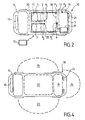
- Figure 7 is a perspective view showing a vehicle in accordance with a third example,
- Figure 8 shows a modified example of the signal transmitter,
- Figure 9 is a perspective view showing a vehicle in accordance with a fourth example,
- Figure 10 is a perspective view showing a vehicle in accordance with a fifth example,
- Figure 11 is a plane view from above showing a vehicle in accordance with an embodiment of the invention.
- All the figures relate to an automotive vehicle equipped with a keyless entry system. The vehicle is designated by
number 10 in Fig. 2. This system includes an on-board central control unit which is able to carry out a two-way radio communication with anelectronic key 12, shown on Fig. 2, in accordance with an encrypted protocol in order to recognize the electronic key and to actuate the vehicle locks once theelectronic key 12 has been recognized. The central control unit includes the antenna drivers and a logical data processing unit, such as a digital processor. For example, the communication can be triggered by actuating a door handle. In the following, the description is focused on the uplink from the on-board central unit to theelectronic key 12. The other elements of the system are known by persons skilled in the art. - The on-board central unit includes a low frequency signal transmitter 11 (operating at e.g. 20 kHz, 125 kHz or 13,56MHz) with a number of output terminals O1-O5 connected by wire conductors 1-5 to a number of connection points P1-P5 on the
vehicle body floor 13. In order to clarify the positions of the connection points, some usual components of the vehicle are shown in dot-dashed lines on Fig. 2,i.e. air intake 15,engine compartment 16,front seats 17,back seats 18,luggage compartment 19,passenger compartment 20 andrear lights 21. For example, P1 and P2 are located on both sides of the transmission tunnel in the middle of thepassenger compartment 20. - The wire conductors 1-5 are preferably arranged in the existing wiring harnesses of the vehicle, i.e. the collection of wires and cables which supply power and/or data signals to different elements of the vehicle. For example, a wiring harness for the rear lights is generally arranged in a tunnel which runs along the bottom of the door frames. The wire conductors 1-5 are individually insulated by an insulating covering.
- The wire conductors 1-5 and the corresponding connection points P1-P5 are arranged in such a manner that a number of specific areas inside the vehicle are substantially surrounded each by a hybrid loop made of a pair of the wire conductors and the portion of the body floor located between the corresponding pair of connection points. For example, as shown in Figs.1 and 2, the front middle portion of the passenger compartment, i.e. between the
front seats 17, is substantially surrounded bywire conductors luggage compartment 19 andwire conductors passenger compartment 20 andwire conductors 1 and 3; the left-hand side ofpassenger compartment 20 andwire conductors transmitter 11 selects one of the above mentioned pair of wire conductors and generates an electrical current into it, so that the resulting magnetic field will have greater amplitude in the corresponding specified area than anywhere else. When a signal is transmitted to the electronic key 12 using a selected pair of wire conductors, a specific antenna identification code can be included in the signal in order to identify the corresponding transmission antenna. - The portions of the wire conductors 1-5 which follow the same path are twisted together, as shown with dashed lines in Fig. 3. Wire conductors 1-3 form an intertwined bundle of
wire conductors 22 which extends from thetransmitter 11 up to a branching point B2 wherewire 2 separates from the bundle and a branching point B1 wherewire 1 separates from wire 3. The additional portion of intertwined wires does not affect the magnetic field of the hybrid loop antennas. - Fig. 5 shows the
transmitter 11 with output selection means in more details. The transmitter includes an electrical generator 30 which generates electrical current in the primary winding 32 of acurrent transformer 31. The electrical generator 30 can be designed as thedriver circuit 56 of Fig. 1. The secondary winding 33 oftransformer 31 is connectable to different pairs of the output terminals O1-O5 through aswitching device 34 comprising four contact relays A-D. Tuning capacitors C1-C4 are connected between the relays A, B and D and the output terminals O1, O3 and O5. A different capacitor is needed for tuning each hybrid loop if they have a different inductivity. Each contact relay has a default position denoted by 0 and an activated position denoted by 1. The relays A-D are controlled by the central unit of the system (not shown). - Based on this antenna architecture, it should be possible to detect the electronic key 12 in every possible situation inside and outside the
vehicle 10. Possible transmission areas inside and outside the vehicle are shown in Fig. 4.Area 20 is inside the passenger compartment.Area 19 is inside the luggage compartment.Area 23 is outside the vehicle on the left-hand side.Area 24 is outside the vehicle behind the luggage compartment.Area 25 is outside the vehicle on the right-hand side. - To find out the current position of the
electronic key 12 inside or outside the car, the hybrid loop antennas are driven sequentially as described in Table 1 with the same power level or with different levels. The process for locating theelectronic key 12 is based on a measurement of the field amplitude at the electronic key reception antenna. Accordingly, every time it receives a signal, the electronic key 12 measures the field amplitude (i.e. an electric tension at the receiving antenna) and communicates that value to the on-board central unit, together with the antenna identification code as the case may be. The on-board central unit detects that theelectronic key 12 is in one of the transmission areas when it receives a response to a signal which was transmitted using to the corresponding activated wires and when the corresponding field measurement condition is verified. - In Table 1, the factors k0 and k1 are preset levels (k0=k1 or k0<k1), which define whether the key is inside or outside the car. Such preset levels can be achieved with experimental calibration measurements. Although the status of relay D does not matter in some cases, a simpler control of the switching device is achieved by using the same control signal for switching both relays C and D together (i.e. C status=D status at all times).
- Fig 6 shows a second example 110 of the vehicle. The connection points P3 and P5 are modified to P'3 and P'5 in comparison to the first example. The
transmitter 111 is placed at the right-hand front comer of the vehicle compartment instead of the left-hand rear comer. The elements which are identical or analogous to those of the first example are denoted by the same reference number increased by 100. Thetransmitter 111 is identical to thetransmitter 11 of Fig. 5 and is connected to wire conductors 101-105 as shown in Fig. 5. Wire portions which follow the same path are preferably twisted or intertwined together. The transmission areas are substantially the same as in the first example. The detection of the electronic key is carried out in the same manner, using the switching and detection rules shown in Table 2. Here, the default position of the contact relays A-D is selected in such a manner that the antenna wire conductors which are excited in that position are those which cover a transmission zone located on the driver's lateral side of the vehicle (area 23), so that a faster response time is obtained when the driver requests access to the car by actuating the driver door handle. - Fig 7 shows a third example 210 of the vehicle. The doors are omitted for the sake of clarity. The elements which are identical or analogous to those of the first example are denoted by the same reference number increased by 200. The
transmitter 211 is placed on the left-hand side of the luggage compartment and has a circuitry similar to that shown on Fig. 5 with three output terminals to which wire conductors 201-203 are connected.Wire conductors body floor 213 from thetransmitter 211 up to a branching point B3 located at the bottom of the left-handcentral pillar 40. This first portion ofwire conductors wire pair 222 with a regular helical intertwining in order to minimize the magnetic radiation of this portion. From point B3,wire 201 extends along thebody floor 213, along the front side of thefront door frame 44 and up the left-hand front pillar 41 up to connection point P201. From point B3,wire 202 runs along thecentral pillar 40 up to connection point P202. Wire 203 runs along the left-handrear pillar 42 up to connection point P203. Connection points P201-P203 are located on the left-hand side of thevehicle roof 43 so that electrical current can flow from one to the other. - When
wire conductors areas wire conductors areas - In an example alternative to that of Fig. 5, the transmitter includes electrical driving means in the form of several driver circuits connected to different pairs of output terminals. The central control unit is provided with driver circuit selection means operable in several states for selectively activating the different driver circuits. A switching device such as
device 34 is not needed in that case. - With the transmitter type shown in Fig. 5, the antenna wire conductors are fed through a
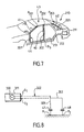
transformer 31, which prevents any short-circuited connection between the driver circuit and the vehicle body from occurring. Alternatively, it is possible to drive the antenna wire conductors directly without a transformer, as shown in the modified embodiment of Fig. 8. As shown in Fig. 8, the modifiedtransmitter 311 includes a low frequency generator 330 (e.g. 20 kHz or 125 kHz) with two output terminals O1 and O2 which are connected to the vehicle body at connection points P1 and P2 throughwire conductors Number 322 represents an intertwined portion.Capacitors 47 and 48 are arranged on each wire, for example at the connection points P1 and P2, so as to avoid the risk of a short-circuited connection for DC current between the generator and the vehicle body. While only two antenna output terminals and antenna wire conductors are shown for the sake of conciseness, it is clear that any number of output terminals can be similarly connected to the car body. Again, the corresponding output selection means can take the form of a switching device arranged between a single driver circuit and a number of output terminals or the form of a number of selectable driver circuits or other forms. - Fig 9 shows a fourth example 410 of the vehicle. The elements which are identical or analogous to those of the first example are denoted by the same reference number increased by 400. The
transmitter 411 is placed on the left-hand side of the luggage compartment and has output terminals to whichinsulated wire conductors central pillar 40, thewire conductors body floor 413. This first portion ofwire conductors twisted wire pair 422 with a regular helical intertwining in order to minimize the magnetic radiation of this portion. From point B401,wire 401 has aportion 401a which extends transversally across the vehicle on thebody floor 413 and a portion 401b which runs along the right-hand central pillar up to connection point P401. From point B401,wire 402 runs up thecentral pillar 40 up to connection point P402. Connection points P401 and P402 are located on the underside of thevehicle top 43 at opposite sides of the vehicle body. Thevehicle top 43 makes an electrical connection between both sides of the vehicle. Hence,wires - A similar hybrid loop antenna is obtained in the
vehicle 510 shown on Fig. 10, where elements which are identical or analogous to those of the first example are denoted by the same reference number increased by 500. Here, the intertwinedwire pair 522 runs along the left-handrear pillar 42 of the vehicle body and along the left-hand side of thevehicle body top 43 up to branching point B501 which is located at the top of the left-handcentral pillar 40. From point B501, theinsulated wire 501 has aportion 501 a which extends transversally across the vehicle on the underside of thevehicle top 43 and aportion 501b which runs along the right-hand central pillar down to connection point P501. From point B501,insulated wire 502 runs along thecentral pillar 40 down to connection point P502. Connection points P501 and P502 are located on thebody floor 513 at opposite sides of the vehicle body. Thebody floor 513 makes an electrical connection between both sides of the vehicle. - The hybrid loop antennas of Fig. 9 and 10 can also be made at the front end or at the rear end of the passenger compartment by passing the wires along the front or rear pillars of the vehicle body instead of the centre pillars. The pair of
wires 401/402 or 501/502 shown on Figs. 9 and 10 can be used as the only transmission antenna of the system, in which case only two transmitter outputs are needed. They can also be combined with other hybrid loops as shown in the preceding embodiments, in which case the transmitter will be fitted with more outputs and include output selection means, as described above. - The position of the central control unit with the transmitter and the positions and number of the connection points need not be the same as the illustrative examples shown in the figures. In fact, the path of the antenna wire conductors can be easily adapted to any desired position of the transmitter because suitable locations for connection points are available on most parts of any vehicle body and because intertwined wire pairs can be formed wherever a wire portion is not intended to radiate. In other words, the proposed antenna architecture offers great flexibility.
- With reference to Figure 11, the only embodiment of the invention is now described. The same reference numbers as in Fig. 2 refer to the same vehicle elements as in the first example. In
vehicle 610, thetransmitter 611 has two output terminals which feed two series-connectedloop antennas loop antennas passenger compartment 20 and theluggage compartment area 19, respectively.Loop antenna 61 is located on thebody floor 13 at the centre of thepassenger compartment 20, i.e. around the transmission tunnel and gear box.Loop antenna 62 is located on thebody floor 13 around theluggage compartment area 19, as seen from above on Fig. 11. Both loops are series-connected through an intertwinedwire pair 60, which does not affect the radiation pattern of each loop. An intertwinedwire pair 622 is also used for connectingloop antenna 62 to the transmitter output terminals. - More precisely, intertwined
wire pair 622 extends from the transmitter output terminals to a first branching point B601 where twowire portions Wire portions luggage compartment 19 in mutually opposite directions down to meeting point B603 which is located in the middle of the vehicle at the front side of the luggage compartment. From points B601 to B603;wire portions form loop antenna 62. At point B603,wire portions wire pair 60 which extends longitudinally along thebody floor 13 down to a second branching point B602 where twowire portions wire portions loop antenna 61. - Both loop antennas and both intertwined wire pairs can be made with a single uninterrupted wire. They can also be made of a number of shorter wire portions which are series-connected with appropriate connectors, in order to simplify the installation of the antenna assembly. As a preference, the corresponding wire or wire portions are placed in the wiring harnesses of the vehicle. Alternatively, they can be connected through one or more standard connectors between different on-board system modules of the vehicle.
-
Transmitter 611 includes an antenna driver circuit, which can be similar to that shown on Fig. 1, i.e. with an electrical current transformer for impedance matching. - More than two series-connected loop antennas can be formed similarly. In this embodiment, a very simple and cost-effective antenna assembly is obtained, which provides a number of well-defined transmission areas, because the intertwined wire portions not affect the radiation pattern of the loop antennas, while making it possible to use a simple driver circuit with two output terminals.
- The invention is also applicable to keyless ignition systems.
Table 1: detection logic for localising the electronic key in the example of Fig. 2 Transmission area (see Fig. 4) Activated Wires Condition on Field Measurement Status of Relays (see Fig. 5) 20 1 and 2 Field Strength>k1 A=0, B=1 C=0, D=0 19 4 and 5 Field Strength>k1 A=1, B=0 or 1 C=1, D=0 or 1 23 2 and 4 Field Strength<k0 A=0, B=1 C=1, D=1 24 4 and 5 Field Strength<k0 A=1, B=0 or 1 C=1, D=0 or 1 25 1 and 3 Field Strength<k0 A=0, B=0 C=0, D=0 or 1 Table 2: detection logic for localising the electronic key in the example of Fig. 6 Transmission area (see Fig. 4) Activated Wires Condition on Field Measurement Status of Relays (see Fig. 5) 20 101 and 102 Field Strength>k1 A=0, B=1 C=0, D=0 19 104 and 105 Field Strength>k1 A=1, B=0 or 1 C=1, D=0 or 1 23 102 and 103 Field Strength<k0 A=0, B=0 C=0, D=0 or 1 24 104 and 105 Field Strength<k0 A= 1, B=0 or 1 C=1, D=0 or 1 25 101 and 104 Field Strength<k0 A=0, B=1 C=1, D=1
Claims (10)
- Vehicle (610) comprising an on-board signal transmitter (611) capable of communicating with a portable receiver (12) for implementing a keyless entry and/or keyless ignition procedure, said signal transmitter having a loop antenna (61) made of conductive material and arranged around at least a portion of the vehicle interior space (19, 20), as seen in projection, for radiating a magnetic field, said loop antenna (61) being connected to the signal transmitter by two wire conductors which extend from the signal transmitter,
wherein the two wire conductors (601, 602) are twisted together along a portion of their length (60) down to a branching point (B602) where the two wire conductors separate from one another in order to form at least a portion of said loop antenna (61),
characterized in that a portion (603, 604) of the two wire.conductors located between the branching point (B602) and said transmitter (611) forms a second loop antenna (62) arranged around at least a portion of the vehicle interior space, as seen in projection, wherein an intertwined portion of said two wire conductors connects both loop antennas (61, 62) in series and a further intertwined portion (622) of said two wire conductors extends between said second loop antenna (62) and said transmitter (611). - Vehicle as claimed in claim 1, characterized in that said loop antenna (61) is entirely constituted by said wire conductors (601, 602).
- Vehicle as claimed in claim 2, characterized in that the two wire conductors (601, 602) are two portions of a single wire in an uninterrupted circuit which is arranged in the form of a whole loop (61).
- Vehicle as claimed in claim 1, characterized in that both loop antennas (61, 62) and both intertwined pairs (60, 622) are made of a single wire in an uninterrupted circuit, wherein the two wire conductors are two portions of said single wire.
- Vehicle as claimed in any one of claims 1 to 4, characterized in that at least one loop is formed around the luggage compartment (19) of the vehicle, as seen in vertical projection.
- Vehicle as claimed in any one of claims 1 to 5, characterized in that at least one loop is formed around a centre portion of the passenger compartment (20) of the vehicle, as seen in vertical projection.
- Vehicle as claimed in any one of claims 1 to 6, characterized in that at least one loop is formed around a right-hand half and/or a left-hand half of the passenger compartment (20) of the vehicle, as seen in vertical projection.
- Vehicle as claimed in any one of claims 1 to 7, characterized in that at least one loop is formed around a front half and/or a rear half of the passenger compartment (20) of the vehicle, as seen in lateral projection.
- Vehicle as claimed in any one of claims 1 to 8, characterized in that at least one loop is formed around the passenger compartment (20) of the vehicle, as seen in longitudinal projection.
- Vehicle as claimed in any one of claims 1 to 9, characterized in that the wire conductors (601-604) are arranged within the wiring harnesses of the vehicle.
Applications Claiming Priority (3)
| Application Number | Priority Date | Filing Date | Title |
|---|---|---|---|
| GB0325577 | 2003-11-03 | ||
| GBGB0325577.5A GB0325577D0 (en) | 2003-11-03 | 2003-11-03 | Antenna system |
| EP04291697A EP1548871B1 (en) | 2003-11-03 | 2004-07-05 | On-board signal transmitter for implementing keyless procedure |
Related Parent Applications (1)
| Application Number | Title | Priority Date | Filing Date |
|---|---|---|---|
| EP04291697A Division EP1548871B1 (en) | 2003-11-03 | 2004-07-05 | On-board signal transmitter for implementing keyless procedure |
Publications (2)
| Publication Number | Publication Date |
|---|---|
| EP1533865A1 EP1533865A1 (en) | 2005-05-25 |
| EP1533865B1 true EP1533865B1 (en) | 2008-01-23 |
Family
ID=29725821
Family Applications (2)
| Application Number | Title | Priority Date | Filing Date |
|---|---|---|---|
| EP04077304A Active EP1533865B1 (en) | 2003-11-03 | 2004-07-05 | On-board signal transmitter for implementing keyless procedure |
| EP04291697A Active EP1548871B1 (en) | 2003-11-03 | 2004-07-05 | On-board signal transmitter for implementing keyless procedure |
Family Applications After (1)
| Application Number | Title | Priority Date | Filing Date |
|---|---|---|---|
| EP04291697A Active EP1548871B1 (en) | 2003-11-03 | 2004-07-05 | On-board signal transmitter for implementing keyless procedure |
Country Status (4)
| Country | Link |
|---|---|
| EP (2) | EP1533865B1 (en) |
| AT (2) | ATE385053T1 (en) |
| DE (2) | DE602004011449T2 (en) |
| GB (1) | GB0325577D0 (en) |
Families Citing this family (5)
| Publication number | Priority date | Publication date | Assignee | Title |
|---|---|---|---|---|
| DE102005015594B4 (en) * | 2005-04-05 | 2007-04-12 | Texas Instruments Deutschland Gmbh | Non-contact access system and immobilizer with different frequencies using the same antenna coil |
| DE102005032379A1 (en) * | 2005-07-08 | 2007-01-11 | Conti Temic Microelectronic Gmbh | Access control system for a motor vehicle |
| DE502005002506D1 (en) * | 2005-08-01 | 2008-02-21 | Delphi Tech Inc | antenna means |
| EP1777532A1 (en) * | 2005-10-18 | 2007-04-25 | Delphi Technologies, Inc. | Method and driving apparatus for testing an antenna |
| DE102006042344A1 (en) * | 2006-09-08 | 2008-04-03 | Conti Temic Microelectronic Gmbh | Radio arrangement for e.g. remote keyless entry system in passenger car, has antenna electrically connected with radio station by cable, arranged in undersurface of outer side of vehicle and including antenna units |
Family Cites Families (6)
| Publication number | Priority date | Publication date | Assignee | Title |
|---|---|---|---|---|
| JPS6278379A (en) * | 1985-09-30 | 1987-04-10 | 日産自動車株式会社 | Locking and unlocking control apparatus for vehicle |
| US5812095A (en) * | 1995-10-06 | 1998-09-22 | Ford Motor Company | Mounting structure for combined automotive trim accessory and antenna |
| DE19748327A1 (en) * | 1997-10-31 | 1999-05-20 | Siemens Ag | Antenna device, in particular for an anti-theft system of a motor vehicle |
| DE19752149C2 (en) * | 1997-11-25 | 2003-06-18 | Ford Global Tech Inc | Antenna arrangement for keyless use of a vehicle |
| FR2810946B3 (en) * | 2000-07-03 | 2002-04-19 | Valeo Electronique | MOTOR VEHICLE EQUIPPED WITH AN IMPROVED "HANDS-FREE" ACCESS SYSTEM FOR LOCATING A PORTABLE BADGE |
| JP3899505B2 (en) * | 2000-08-30 | 2007-03-28 | オムロン株式会社 | Wireless device |
-
2003
- 2003-11-03 GB GBGB0325577.5A patent/GB0325577D0/en not_active Ceased
-
2004
- 2004-07-05 EP EP04077304A patent/EP1533865B1/en active Active
- 2004-07-05 DE DE602004011449T patent/DE602004011449T2/en active Active
- 2004-07-05 AT AT04077304T patent/ATE385053T1/en not_active IP Right Cessation
- 2004-07-05 AT AT04291697T patent/ATE329379T1/en not_active IP Right Cessation
- 2004-07-05 EP EP04291697A patent/EP1548871B1/en active Active
- 2004-07-05 DE DE602004001122T patent/DE602004001122T2/en active Active
Also Published As
| Publication number | Publication date |
|---|---|
| DE602004011449T2 (en) | 2009-01-15 |
| ATE329379T1 (en) | 2006-06-15 |
| EP1548871A1 (en) | 2005-06-29 |
| EP1533865A1 (en) | 2005-05-25 |
| DE602004001122T2 (en) | 2007-01-04 |
| GB0325577D0 (en) | 2003-12-03 |
| DE602004011449D1 (en) | 2008-03-13 |
| DE602004001122D1 (en) | 2006-07-20 |
| EP1548871B1 (en) | 2006-06-07 |
| ATE385053T1 (en) | 2008-02-15 |
Similar Documents
| Publication | Publication Date | Title |
|---|---|---|
| US20050159131A1 (en) | Communicator and vehicle controller | |
| US6563474B2 (en) | Remote access device having multiple inductive coil antenna | |
| US9378603B2 (en) | Keyless entry system | |
| JP2546842B2 (en) | Vehicle locking / unlocking control device | |
| US8614645B2 (en) | Antenna module for a motor vehicle | |
| US5723912A (en) | Remote keyless entry system having a helical antenna | |
| EP0889538B1 (en) | Antenna apparatus for vehicles | |
| US20040257296A1 (en) | Door handle for a vehicle | |
| EP1533865B1 (en) | On-board signal transmitter for implementing keyless procedure | |
| JP4985106B2 (en) | On-vehicle antenna device and array antenna | |
| US6392607B1 (en) | Antenna system especially for an anti-theft system of a motor vehicle | |
| KR100767479B1 (en) | Method for Displaying Vehicle Security Status And Smart Key System Using The Same | |
| JP4297934B2 (en) | Vehicle communication device | |
| JP5088026B2 (en) | Smart keyless entry system | |
| US6937197B2 (en) | Antenna for a central locking system of an automotive vehicle | |
| JP3826881B2 (en) | Vehicle door handle device | |
| JP2008078971A (en) | In-vehicle wireless receiver and wireless-receiver setting method | |
| US7106263B2 (en) | Window-integrated antenna for LMS and diversitary FM reception in mobile motor vehicles | |
| JP4638814B2 (en) | Communication device | |
| JP4638297B2 (en) | Portable machine | |
| JP4641232B2 (en) | Vehicle antenna device | |
| JP2007174237A (en) | Receiver for vehicle | |
| WO2019142656A1 (en) | On-vehicle antenna device | |
| JP2544055B2 (en) | Automotive glass antenna | |
| JP4382476B2 (en) | Automotive identification device |
Legal Events
| Date | Code | Title | Description |
|---|---|---|---|
| PUAI | Public reference made under article 153(3) epc to a published international application that has entered the european phase |
Free format text: ORIGINAL CODE: 0009012 |
|
| 17P | Request for examination filed |
Effective date: 20050212 |
|
| AK | Designated contracting states |
Kind code of ref document: A1 Designated state(s): AT BE BG CH CY CZ DE DK EE ES FI FR GB GR HU IE IT LI LU MC NL PL PT RO SE SI SK TR |
|
| AX | Request for extension of the european patent |
Extension state: AL HR LT LV MK |
|
| AKX | Designation fees paid |
Designated state(s): AT BE BG CH CY CZ DE DK EE ES FI FR GB GR HU IE IT LI LU MC NL PL PT RO SE SI SK TR |
|
| 17Q | First examination report despatched |
Effective date: 20070621 |
|
| GRAP | Despatch of communication of intention to grant a patent |
Free format text: ORIGINAL CODE: EPIDOSNIGR1 |
|
| GRAS | Grant fee paid |
Free format text: ORIGINAL CODE: EPIDOSNIGR3 |
|
| GRAA | (expected) grant |
Free format text: ORIGINAL CODE: 0009210 |
|
| AC | Divisional application: reference to earlier application |
Ref document number: 1548871 Country of ref document: EP Kind code of ref document: P |
|
| AK | Designated contracting states |
Kind code of ref document: B1 Designated state(s): AT BE BG CH CY CZ DE DK EE ES FI FR GB GR HU IE IT LI LU MC NL PL PT RO SE SI SK TR |
|
| REG | Reference to a national code |
Ref country code: GB Ref legal event code: FG4D |
|
| REG | Reference to a national code |
Ref country code: CH Ref legal event code: EP |
|
| REG | Reference to a national code |
Ref country code: IE Ref legal event code: FG4D |
|
| REF | Corresponds to: |
Ref document number: 602004011449 Country of ref document: DE Date of ref document: 20080313 Kind code of ref document: P |
|
| NLV1 | Nl: lapsed or annulled due to failure to fulfill the requirements of art. 29p and 29m of the patents act | ||
| PG25 | Lapsed in a contracting state [announced via postgrant information from national office to epo] |
Ref country code: ES Free format text: LAPSE BECAUSE OF FAILURE TO SUBMIT A TRANSLATION OF THE DESCRIPTION OR TO PAY THE FEE WITHIN THE PRESCRIBED TIME-LIMIT Effective date: 20080504 Ref country code: LI Free format text: LAPSE BECAUSE OF FAILURE TO SUBMIT A TRANSLATION OF THE DESCRIPTION OR TO PAY THE FEE WITHIN THE PRESCRIBED TIME-LIMIT Effective date: 20080123 Ref country code: FI Free format text: LAPSE BECAUSE OF FAILURE TO SUBMIT A TRANSLATION OF THE DESCRIPTION OR TO PAY THE FEE WITHIN THE PRESCRIBED TIME-LIMIT Effective date: 20080123 Ref country code: CH Free format text: LAPSE BECAUSE OF FAILURE TO SUBMIT A TRANSLATION OF THE DESCRIPTION OR TO PAY THE FEE WITHIN THE PRESCRIBED TIME-LIMIT Effective date: 20080123 |
|
| ET | Fr: translation filed | ||
| REG | Reference to a national code |
Ref country code: CH Ref legal event code: PL |
|
| PG25 | Lapsed in a contracting state [announced via postgrant information from national office to epo] |
Ref country code: AT Free format text: LAPSE BECAUSE OF FAILURE TO SUBMIT A TRANSLATION OF THE DESCRIPTION OR TO PAY THE FEE WITHIN THE PRESCRIBED TIME-LIMIT Effective date: 20080123 Ref country code: BG Free format text: LAPSE BECAUSE OF FAILURE TO SUBMIT A TRANSLATION OF THE DESCRIPTION OR TO PAY THE FEE WITHIN THE PRESCRIBED TIME-LIMIT Effective date: 20080423 |
|
| PG25 | Lapsed in a contracting state [announced via postgrant information from national office to epo] |
Ref country code: BE Free format text: LAPSE BECAUSE OF FAILURE TO SUBMIT A TRANSLATION OF THE DESCRIPTION OR TO PAY THE FEE WITHIN THE PRESCRIBED TIME-LIMIT Effective date: 20080123 Ref country code: PL Free format text: LAPSE BECAUSE OF FAILURE TO SUBMIT A TRANSLATION OF THE DESCRIPTION OR TO PAY THE FEE WITHIN THE PRESCRIBED TIME-LIMIT Effective date: 20080123 Ref country code: PT Free format text: LAPSE BECAUSE OF FAILURE TO SUBMIT A TRANSLATION OF THE DESCRIPTION OR TO PAY THE FEE WITHIN THE PRESCRIBED TIME-LIMIT Effective date: 20080623 Ref country code: SI Free format text: LAPSE BECAUSE OF FAILURE TO SUBMIT A TRANSLATION OF THE DESCRIPTION OR TO PAY THE FEE WITHIN THE PRESCRIBED TIME-LIMIT Effective date: 20080123 |
|
| PG25 | Lapsed in a contracting state [announced via postgrant information from national office to epo] |
Ref country code: SE Free format text: LAPSE BECAUSE OF FAILURE TO SUBMIT A TRANSLATION OF THE DESCRIPTION OR TO PAY THE FEE WITHIN THE PRESCRIBED TIME-LIMIT Effective date: 20080423 Ref country code: CZ Free format text: LAPSE BECAUSE OF FAILURE TO SUBMIT A TRANSLATION OF THE DESCRIPTION OR TO PAY THE FEE WITHIN THE PRESCRIBED TIME-LIMIT Effective date: 20080123 Ref country code: DK Free format text: LAPSE BECAUSE OF FAILURE TO SUBMIT A TRANSLATION OF THE DESCRIPTION OR TO PAY THE FEE WITHIN THE PRESCRIBED TIME-LIMIT Effective date: 20080123 Ref country code: NL Free format text: LAPSE BECAUSE OF FAILURE TO SUBMIT A TRANSLATION OF THE DESCRIPTION OR TO PAY THE FEE WITHIN THE PRESCRIBED TIME-LIMIT Effective date: 20080123 Ref country code: SK Free format text: LAPSE BECAUSE OF FAILURE TO SUBMIT A TRANSLATION OF THE DESCRIPTION OR TO PAY THE FEE WITHIN THE PRESCRIBED TIME-LIMIT Effective date: 20080123 |
|
| PG25 | Lapsed in a contracting state [announced via postgrant information from national office to epo] |
Ref country code: RO Free format text: LAPSE BECAUSE OF FAILURE TO SUBMIT A TRANSLATION OF THE DESCRIPTION OR TO PAY THE FEE WITHIN THE PRESCRIBED TIME-LIMIT Effective date: 20080123 |
|
| PLBE | No opposition filed within time limit |
Free format text: ORIGINAL CODE: 0009261 |
|
| STAA | Information on the status of an ep patent application or granted ep patent |
Free format text: STATUS: NO OPPOSITION FILED WITHIN TIME LIMIT |
|
| 26N | No opposition filed |
Effective date: 20081024 |
|
| GBPC | Gb: european patent ceased through non-payment of renewal fee |
Effective date: 20080705 |
|
| PG25 | Lapsed in a contracting state [announced via postgrant information from national office to epo] |
Ref country code: MC Free format text: LAPSE BECAUSE OF NON-PAYMENT OF DUE FEES Effective date: 20080731 |
|
| PG25 | Lapsed in a contracting state [announced via postgrant information from national office to epo] |
Ref country code: EE Free format text: LAPSE BECAUSE OF FAILURE TO SUBMIT A TRANSLATION OF THE DESCRIPTION OR TO PAY THE FEE WITHIN THE PRESCRIBED TIME-LIMIT Effective date: 20080123 |
|
| PG25 | Lapsed in a contracting state [announced via postgrant information from national office to epo] |
Ref country code: GB Free format text: LAPSE BECAUSE OF NON-PAYMENT OF DUE FEES Effective date: 20080705 |
|
| PG25 | Lapsed in a contracting state [announced via postgrant information from national office to epo] |
Ref country code: IE Free format text: LAPSE BECAUSE OF NON-PAYMENT OF DUE FEES Effective date: 20080707 Ref country code: CY Free format text: LAPSE BECAUSE OF FAILURE TO SUBMIT A TRANSLATION OF THE DESCRIPTION OR TO PAY THE FEE WITHIN THE PRESCRIBED TIME-LIMIT Effective date: 20080123 |
|
| PG25 | Lapsed in a contracting state [announced via postgrant information from national office to epo] |
Ref country code: HU Free format text: LAPSE BECAUSE OF FAILURE TO SUBMIT A TRANSLATION OF THE DESCRIPTION OR TO PAY THE FEE WITHIN THE PRESCRIBED TIME-LIMIT Effective date: 20080724 Ref country code: LU Free format text: LAPSE BECAUSE OF NON-PAYMENT OF DUE FEES Effective date: 20080705 |
|
| PG25 | Lapsed in a contracting state [announced via postgrant information from national office to epo] |
Ref country code: TR Free format text: LAPSE BECAUSE OF FAILURE TO SUBMIT A TRANSLATION OF THE DESCRIPTION OR TO PAY THE FEE WITHIN THE PRESCRIBED TIME-LIMIT Effective date: 20080123 |
|
| PG25 | Lapsed in a contracting state [announced via postgrant information from national office to epo] |
Ref country code: GR Free format text: LAPSE BECAUSE OF FAILURE TO SUBMIT A TRANSLATION OF THE DESCRIPTION OR TO PAY THE FEE WITHIN THE PRESCRIBED TIME-LIMIT Effective date: 20080424 |
|
| REG | Reference to a national code |
Ref country code: FR Ref legal event code: TP Owner name: DELPHI INTERNATIONAL OPERATIONS LUXEMBOURG S.A, LU Effective date: 20131218 |
|
| REG | Reference to a national code |
Ref country code: DE Ref legal event code: R081 Ref document number: 602004011449 Country of ref document: DE Owner name: DELPHI INTERNATIONAL OPERATIONS LUXEMBOURG S.A, LU Free format text: FORMER OWNER: DELPHI TECHNOLOGIES, INC., TROY, US Effective date: 20140410 Ref country code: DE Ref legal event code: R082 Ref document number: 602004011449 Country of ref document: DE Representative=s name: REITSTOETTER KINZEBACH, DE Effective date: 20140410 Ref country code: DE Ref legal event code: R081 Ref document number: 602004011449 Country of ref document: DE Owner name: DELPHI INTERNATIONAL OPERATIONS LUXEMBOURG S.A, LU Free format text: FORMER OWNER: DELPHI TECHNOLOGIES, INC., TROY, MICH., US Effective date: 20140410 |
|
| REG | Reference to a national code |
Ref country code: FR Ref legal event code: PLFP Year of fee payment: 13 |
|
| REG | Reference to a national code |
Ref country code: FR Ref legal event code: PLFP Year of fee payment: 14 |
|
| REG | Reference to a national code |
Ref country code: FR Ref legal event code: PLFP Year of fee payment: 15 |
|
| REG | Reference to a national code |
Ref country code: DE Ref legal event code: R081 Ref document number: 602004011449 Country of ref document: DE Owner name: APTIV TECHNOLOGIES LIMITED, BB Free format text: FORMER OWNER: DELPHI INTERNATIONAL OPERATIONS LUXEMBOURG S.A R.L., 4940 HAUTCHARAGE, LU Ref country code: DE Ref legal event code: R082 Ref document number: 602004011449 Country of ref document: DE Ref country code: DE Ref legal event code: R081 Ref document number: 602004011449 Country of ref document: DE Owner name: APTIV TECHNOLOGIES LIMITED, BB Free format text: FORMER OWNER: DELPHI INTERNATIONAL OPERATIONS LUXEMBOURG S.A R.L., 4940 BASCHARAGE, LU |
|
| PGFP | Annual fee paid to national office [announced via postgrant information from national office to epo] |
Ref country code: IT Payment date: 20190726 Year of fee payment: 16 Ref country code: FR Payment date: 20190725 Year of fee payment: 16 |
|
| PG25 | Lapsed in a contracting state [announced via postgrant information from national office to epo] |
Ref country code: FR Free format text: LAPSE BECAUSE OF NON-PAYMENT OF DUE FEES Effective date: 20200731 |
|
| PG25 | Lapsed in a contracting state [announced via postgrant information from national office to epo] |
Ref country code: IT Free format text: LAPSE BECAUSE OF NON-PAYMENT OF DUE FEES Effective date: 20200705 |
|
| P01 | Opt-out of the competence of the unified patent court (upc) registered |
Effective date: 20230425 |
|
| PGFP | Annual fee paid to national office [announced via postgrant information from national office to epo] |
Ref country code: DE Payment date: 20230725 Year of fee payment: 20 |