EP1533797A1 - Optical information recording medium - Google Patents
Optical information recording medium Download PDFInfo
- Publication number
- EP1533797A1 EP1533797A1 EP03795223A EP03795223A EP1533797A1 EP 1533797 A1 EP1533797 A1 EP 1533797A1 EP 03795223 A EP03795223 A EP 03795223A EP 03795223 A EP03795223 A EP 03795223A EP 1533797 A1 EP1533797 A1 EP 1533797A1
- Authority
- EP
- European Patent Office
- Prior art keywords
- pits
- land pre
- optical information
- information recording
- recording media
- Prior art date
- Legal status (The legal status is an assumption and is not a legal conclusion. Google has not performed a legal analysis and makes no representation as to the accuracy of the status listed.)
- Withdrawn
Links
Images








Classifications
-
- G—PHYSICS
- G11—INFORMATION STORAGE
- G11B—INFORMATION STORAGE BASED ON RELATIVE MOVEMENT BETWEEN RECORD CARRIER AND TRANSDUCER
- G11B7/00—Recording or reproducing by optical means, e.g. recording using a thermal beam of optical radiation by modifying optical properties or the physical structure, reproducing using an optical beam at lower power by sensing optical properties; Record carriers therefor
- G11B7/24—Record carriers characterised by shape, structure or physical properties, or by the selection of the material
- G11B7/2407—Tracks or pits; Shape, structure or physical properties thereof
- G11B7/24085—Pits
-
- G—PHYSICS
- G11—INFORMATION STORAGE
- G11B—INFORMATION STORAGE BASED ON RELATIVE MOVEMENT BETWEEN RECORD CARRIER AND TRANSDUCER
- G11B7/00—Recording or reproducing by optical means, e.g. recording using a thermal beam of optical radiation by modifying optical properties or the physical structure, reproducing using an optical beam at lower power by sensing optical properties; Record carriers therefor
- G11B7/007—Arrangement of the information on the record carrier, e.g. form of tracks, actual track shape, e.g. wobbled, or cross-section, e.g. v-shaped; Sequential information structures, e.g. sectoring or header formats within a track
-
- G—PHYSICS
- G11—INFORMATION STORAGE
- G11B—INFORMATION STORAGE BASED ON RELATIVE MOVEMENT BETWEEN RECORD CARRIER AND TRANSDUCER
- G11B7/00—Recording or reproducing by optical means, e.g. recording using a thermal beam of optical radiation by modifying optical properties or the physical structure, reproducing using an optical beam at lower power by sensing optical properties; Record carriers therefor
- G11B7/007—Arrangement of the information on the record carrier, e.g. form of tracks, actual track shape, e.g. wobbled, or cross-section, e.g. v-shaped; Sequential information structures, e.g. sectoring or header formats within a track
- G11B7/00745—Sectoring or header formats within a track
-
- G—PHYSICS
- G11—INFORMATION STORAGE
- G11B—INFORMATION STORAGE BASED ON RELATIVE MOVEMENT BETWEEN RECORD CARRIER AND TRANSDUCER
- G11B7/00—Recording or reproducing by optical means, e.g. recording using a thermal beam of optical radiation by modifying optical properties or the physical structure, reproducing using an optical beam at lower power by sensing optical properties; Record carriers therefor
- G11B7/24—Record carriers characterised by shape, structure or physical properties, or by the selection of the material
- G11B7/2407—Tracks or pits; Shape, structure or physical properties thereof
- G11B7/24073—Tracks
- G11B7/24082—Meandering
Definitions
- This invention relates to optical information recording media, and in particular to optical information recording media having an optical recording layer, comprising at least light absorbing material or similar, and a metal film or other light reflecting layer on a translucent substrate, and which is capable of recording and reproduction at high density and at high speed, using for example short-wavelength red laser light of wavelength 630 to 670 nm or blue laser light of wavelength 400 to 410 nm.
- DVD-R Digital Versatile (or Video) Disc Writable
- CD-R Compact Disc Writable
- Differences include, for example, the fact that the optical pickup uses short-wavelength red laser light of wavelength 630 to 670 nm and an objective lens with a high numerical aperture (NA) of 0.6 to 0.65.
- NA numerical aperture
- Fig. 15 is an enlarged plane view of principal portions of conventional optical information recording media 1 and a graph of the RF signals and land pre-pit signals thereof;
- Fig. 16 is a cross-sectional view along line XVI-XVI in Fig. 15;
- Fig. 17 is a cross-sectional view along line XVII-XVII in Fig. 15;
- Fig. 18 is a cross-sectional view along line XVIII-XVIII in Fig. 15.
- the optical information recording media 1 has a translucent substrate 2, a light absorbing layer 3 (optical recording layer) formed on the substrate 2, a light reflecting layer 4 formed on the light absorbing layer 3, and a protective layer 5 formed on the light reflecting layer 4.
- a spiral-shape pregroove 6 is formed in the above substrate 2. On the left and right of this pregroove are positioned portions other than the pregroove 6, that is, lands 7. Land pre-pits 8 are formed at a prescribed period in the lands 7, and address information and other sector information is recorded.
- the optical information recording media 1 when the optical information recording media 1 is irradiated with laser light 9 (recording light, forming the circular spot 9S in Fig. 15), the light absorbing layer 3 absorbs the energy of this laser light 9 and so is heated, and thermal transformation occurs on the side of the substrate 2 to form the recorded pit 10.
- laser light 9 recording light, forming the circular spot 9S in Fig. 15
- the light absorbing layer 3 absorbs the energy of this laser light 9 and so is heated, and thermal transformation occurs on the side of the substrate 2 to form the recorded pit 10.
- Fig. 15 mainly depicts the pregrooves 6, lands 7, land pre-pits 8, and recorded pit 10, omitting the light reflecting layer 5 and protective layer 5 of the optical information recording media 1.
- the substrate 2 and light absorbing layer 3 are in contact at the first layer interface 11.
- the light absorbing layer 3 and light reflecting layer 4 are in contact at the second layer interface 12.
- the light reflecting layer 4 and protective layer 5 are in contact at the third layer interface 13.
- the translucent substrate 2 is formed primarily from a resin with excellent shock resistance, and which is a material with high transparency and with refractive index for laser light in the range of, for example, 1.4 to 1.6 approximately; for example, polycarbonate, glass plate, acrylic plate, epoxy plate, or similar may be used.
- the light absorbing layer 3 is a layer comprising light absorbing material (light-absorption material) formed on the substrate 2; upon irradiation with laser light 9, this layer undergoes heating, fusion, sublimation, deformation, or degeneration.
- This light absorbing layer 3 uniformly coating the surface of the substrate 2 with a cyanine dye or similar, dissolved in a solvent, using spin-coating or other means.
- an arbitrary optical recording material can be adopted, but an optically absorptive organic dye is preferable.
- the light reflecting layer 4 is a metal film, formed by evaporation deposition, sputtering or similar means from for example gold, silver, copper, aluminum, or an alloy comprising any of these.
- the protective layer 5 is formed from a resin having excellent shock resistance, similar to the substrate 2.
- an ultraviolet-curing resin may be applied by a spin-coating method and then cured by irradiation with ultraviolet rays to form the layer.
- the RF signal (on the left side in the figure) of a recorded pit 10 not adjacent to a land pre-pit 8 is obtained at an appropriate level.
- a land pre-pit signal (in the center of the figure) for a land pre-pit 8 not adjacent to a recorded pit 10 can also be obtained at an appropriate level.
- the signal amplitude decreases, and the AR (Aperture Ratio, an index of the rate of decrease in amplitude) declines.
- the AR is the ratio (as a percentage) of the land pre-pit signal in a portion in which there is a maximum-length recorded pit 10 to the land pre-pit signal in a portion with no recorded pit 10; the DVD-R standard requires that the AR be 15% or higher.
- Fluctuations in the RF signal may lead to RF readout errors; the DVD-R standard requires, as a criterion for fluctuation of RF signals, that RF readout errors be fewer than 250.
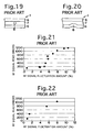
- Fig. 21 is a graph showing RF readout errors in relation to the amount of fluctuation in the RF signal in the case of circular land pre-pits 8.
- Fig. 22 is a graph showing RF readout errors in relation to the amount of fluctuation in the RF signal in the case of meandering land pre-pits 8.
- meandering land pre-pits 8 have a narrower margin with respect to the amount of RF signal fluctuation resulting in an error, and the optimal design range for such pre-pits must be set strictly with respect to various optical pickup types and spot dimensions, as well as angular fluctuations, focal fluctuations, tracking fluctuations, and other disturbances which readily occur at high speeds in particular.
- meandering land pre-pits 8 that the extent or protrusion length on the inside and outside of the arc portion of the meandering shape, or the distance between arc end portions, cannot easily be set in an appropriate combination for the inside and for the outside.
- the amount of RF signal fluctuation is the amount of fluctuation in the level (when there is a land pre-pit 8 adjacent to the recorded pit 10) relative to the level when there is no fluctuation (when there is no land pre-pit 8 adjacent to the recorded pit 10), in percent; in order for there to be fewer than 250 RF readout errors, according to Fig. 22, the RF signal fluctuation amount for meandering land pre-pits 8 must be at least 1% (1% as an absolute value) or lower.
- Fig. 24 is a graph of RF signals for which the unrecorded optical depth is approximately ⁇ /6.2 (similarly, 3T pit signals) and of land pre-pit signals in the same media.
- ⁇ is the wavelength of the laser light 9.
- the unrecorded optical depth can be calculated from the depth of the pregroove 6, the thickness of the dye on the land 7, the thickness of the dye in the pregroove 6, the refractive index n of the dye and substrate 2, and other parameters; but from the graphs of Fig. 23 and Fig. 24, when land pre-pits 8 are circular the extent of fluctuation in the RF signal is seen to depend heavily on the depth of the pregroove 6 and on the thickness of the dye in the deposited film state.
- a meandering land pre-pit 8 is not so greatly influenced by differences in the unrecorded optical depth compared with circular land pre-pits 8, and depending on the deposited film state, optimization is possible without greatly affecting the RF signal.
- meandering land pre-pits 8 when meandering land pre-pits 8 are adopted, if the laser light 9 is shifted from the center direction (detracked) of the optical information recording media 1 (disc) due to some external disturbance, because meandering land pre-pits 8 generally protrude in an arc shape in the outward radial direction of the disc, when a land pre-pit 8 and recorded pit 10 overlap a portion of the land pre-pit 8 encroaches into the recorded pit 10 and affects the shape and size of the recorded pit, so that there is the problem that the recorded pit 10 cannot attain the necessary size and a satisfactory RF signal cannot easily be obtained.
- This invention was devised in light of the above problems, and has as an object the provision of optical information recording media, and in particular DVD-R discs, enabling recording of optical information at high densities.
- a further object of this invention is the provision of optical information recording media in which the shape of meandering land pre-pits is optimized, and address information and other sector information on the optical information recording media can be obtained satisfactorily.
- a further object of this invention is the provision of optical information recording media with optimal design conditions set to reduce land pre-pit readout errors, while simultaneously reducing the RF readout errors of recorded pits.
- a further object of this invention is the provision of optical information recording media enabling the stabilization of RF signal fluctuation amounts up to approximately 1% with respect to meandering land pre-pits in particular, while maintaining a land pre-pit AR (amplitude decrease rate index) of 15% or higher.
- a further object of this invention is the provision of optical information recording media enabling the stabilization of RF signal fluctuation amounts up to approximately 1% even in cases of recording at high speeds of for example four or more times the conventional linear speed (3.5 m/sec), while maintaining a land pre-pit AR (amplitude decrease rate index) of 15% or higher.
- a further object of this invention is the provision of optical information recording media in which, by designing the shape and/or the size of land pre-pits in an optimal relative positional relationship with the energy distribution of the laser light spot, enables acquisition of the land pre-pit signal.
- a further object of this invention is the provision of optical information recording media which can further clarify diffraction of laser light at land pre-pit portions, enabling the acquisition of satisfactory land pre-pit signals.
- a further object of this invention is the provision of optical information recording media enabling optimization of land pre-pit signals, without being greatly influenced by differences in the unrecorded optical depth, and without the state of the deposited film greatly influencing the RF signal.
- a further object of this invention is the provision of optical information recording media in which, by designing the shape and/or the size of land pre-pits in relation to the optimal relative size of recorded pits written by laser light, the signals of the recorded pits and land pre-pits can both be obtained satisfactorily.
- a further object of this invention is the provision of optical information recording media enabling acquisition of the required RF signal, with minimal influence on recorded pits, even when there is shifting from the center direction (detracking) of laser light on the optical information recording media (disc).
- a further object of this invention is the provision of optical information recording media in which, through choice of an appropriate length for land pre-pits in the scanning direction, land pre-pit signals can be obtained.
- this invention is optical information recording media which, focusing on optimization of the shape and/or the size of meandering land pre-pits, the inside protruding portion and outside protruding portion, and the size relative to the laser light spot, has a translucent substrate on which are formed a pregroove and land pre-pits in the lands on either side of the pregroove, an optical recording layer provided on this substrate and enabling recording by recording light, and a light reflecting layer provided on this optical recording layer and which reflects the above recording light, and which enables recording, by irradiation with the above recording light of the above optical recording layer through the above substrate, of information which can be read optically;
- the optical information recording media is characterized in that the above land pre-pits are continuous along the above pregroove and protrude in the radial direction of the above substrate, and that, if e is the base of natural logarithms, then the inside edge portion of the inside protruding portion and the outside edge portion of the outside protru
- the above inside edge portion and the above outside edge portion of the above land pre-pits can be positioned so as to converge toward the center position of the above spot due to the above recording light.
- the shape of meandering land pre-pits can itself be substantially a triangular shape.
- these distances L in and L out can be made smaller than the above spot diameter within the range of the diameter of the spot of the above recording light in the 1/e 2 portion of the Gaussian energy distribution of the spot.
- the inside maximum protrusion portion of the above inside protruding portion, and the outside maximum protrusion portion of the above outside protruding portion can be positioned within the range of the above spot diameter of the above recording light in the 1/e 2 portion of the Gaussian energy distribution of the spot.
- the above inside edge portion and the above outside edge portion can be positioned within the range of the diameter of the spot of the above recording light in the 1/e portion of the Gaussian energy distribution of the spot.
- the shape of meandering land pre-pits which generally protrude in an arc shape, can itself be substantially a triangular shape.
- the above land pre-pits can be made in a triangular shape, an arc shape, a trapezoidal shape, or another arbitrary shape.
- the inside edge portion of the inside protruding portion and the outside edge portion of the outside protruding portion of land pre-pits are positioned to be within the range of the diameter of the spot of the above recording light in the 1/e 2 portion of the Gaussian energy distribution of the spot, so that the diffraction state of laser light irradiating a land pre-pit is satisfactory on the land pre-pit inside and outside and the land pre-pit signal can be more clearly acquired by the laser light, and even when a recorded pit exists near a land pre-pit the effect on the RF signal can be reduced.
- land pre-pit signals can be optimized without being greatly affected by differences in unrecorded optical depths, and depending on the deposited film state, without greatly affecting the RF signal.
- RF fluctuations can be stabilized at approximately 1% during reproduction and the AR of land pre-pits can be maintained at 15% or higher, so that readout errors for RF signals and land pre-pits can be avoided, and necessary sector information can be reliably obtained even from DVD-R discs at high densities and high speeds.
- this invention is optical information recording media which, focusing on optimization of the shape and/or the size of meandering land pre-pits, the inside protruding portion and outside protruding portion, and the size relative to recorded pits, has a translucent substrate on which are formed a pregroove and land pre-pits in the lands on either side of the pregroove, an optical recording layer provided on this substrate and enabling recording of recorded pits by recording light, and a light reflecting layer provided on this optical recording layer and which reflects the above recording light, and which enables recording, by irradiation with the above recording light of the above optical recording layer through the above substrate, of information which can be read optically;
- the optical information recording media is characterized in that the above land pre-pits are continuous along the above pregroove and protrude in the radial direction of the above substrate, and that, if L in is the distance between the two inside edge portions of inside protruding portions of the above land pre-pits, L out is the distance between the
- the above distances L in and L out can be limited to the range 3.36T to 5.22T.
- the above distance L in can be limited to the range 3T to 4T.
- the above distance L in can be limited to the range 3.36T to 3.73T.
- the above distance L out can be limited to the range 4T to 6T.
- the above distance L out can be limited to the range 4.85T to 5.22T.
- the above land pre-pits can be formed in triangular shapes, arc shapes, trapezoidal shapes, or other arbitrary shapes.
- the distance between the two inside edge portions of inside protruding portions of land pre-pits L in and the distance between the two outside edge portions of outside protruding portions of land pre-pits L out are set in the range 3T to 6T, so that even in states in which recorded pits having ten different lengths 3T, 4T, ..., 10T, 11T, 14T overlap with land pre-pits, the RF signal can be obtained satisfactorily without exerting a critical influence on the shape and/or size of recorded pits, and readout errors for land pre-pit signals can also be reduced.
- this invention is optical information recording media which, focusing on appropriate ranges for the distance L in between the two inside edge portions of inside protruding portions of land pre-pits and for the distance L out between the two outside edge portions of outside protruding portions of land pre-pits, has a translucent substrate on which are formed a pregroove and land pre-pits in the lands on either side of the pregroove, an optical recording layer provided on this substrate and enabling recording of recorded pits by recording light, and a light reflecting layer provided on this optical recording layer and which reflects the above recording light, and which enables recording, by irradiation with the above recording light of the above optical recording layer through the above substrate, of information which can be read optically;
- the optical information recording media is characterized in that, when the distance between the two inside edge portions of the above land pre-pits is L in and the distance between the two outside edge portions of the above land pre-pits is L out , these values are set such that 0.40 ⁇ m ⁇ L in ⁇
- the above distances L in and L out can be set such that 0.45 ⁇ m ⁇ L in ⁇ 0.50 ⁇ m and 0.65 ⁇ m ⁇ L out ⁇ 0.70 ⁇ m.
- the above land pre-pits can be formed in a meandering shape.
- the distances L in and L out be in the above range, and so in general the shape of meander-shape or meandering land pre-pits which protrude in an arc shape may be a shape which is substantially triangular.
- the above land pre-pits may be in a triangular shape, an arc shape, a trapezoidal shape, or another arbitrary shape.
- optical information recording media of this invention the third invention
- the conditions for the distances L in and L out of 0.40 ⁇ m ⁇ L in ⁇ 0.80 ⁇ m and 0.40 ⁇ m ⁇ L out ⁇ 0.80 ⁇ m are set, so that the diffraction state of laser light incident on land pre-pits is satisfactory on the land pre-pit outside and inside, a clear land pre-pit signal can be obtained using this laser light, and even when a recorded pit exists near the land pre-pit, the effect on the RF signal can be reduced.
- the land pre-pit signal can be optimized without being greatly influenced by differences in unrecorded optical depth, and depending on the deposited film state, without greatly affecting the RF signal.
- the RF fluctuation amount during reproduction can be stabilized at approximately 1%
- the land pre-pit AR can be maintained at 15% or higher
- readout errors for RF signals and land pre-pits can be avoided, and necessary sector information can be reliably obtained even from DVD-R discs at high densities and high speeds.
- this invention is optical information recording media which, focusing on the arc shape of meandering land pre-pits, the disc radial-direction inside protruding length on the inside of the arc and the radial-direction outside protruding length on the outside of the arc, has a translucent substrate on which are formed a pregroove and land pre-pits in the lands on either side of the pregroove, an optical recording layer provided on this substrate and enabling recording by recording light, and a light reflecting layer provided on this optical recording layer and which reflects the above recording light, and which enables recording, by irradiation with the above recording light of the above optical recording layer through the above substrate, of information which can be read optically;
- the optical information recording media is characterized in that the above land pre-pits are continuous along the above pregroove and protrude in the radial direction of the above substrate in an arc shape, and that, if the inside protrusion length in the radial direction on the inside of the arc
- the above R in and R out can be set such that 0.140 ⁇ m ⁇ R in ⁇ 0.173 ⁇ m and 0.100 ⁇ m ⁇ R out ⁇ 0.192 ⁇ m.
- R in and R out can be set such that R in ⁇ R out .
- R in and R out can be set such that 0.140 ⁇ m ⁇ R in ⁇ 0.156 ⁇ m and 0.156 ⁇ m ⁇ R out ⁇ 0.192 ⁇ m.
- R in and R out can be set such that 0.120 ⁇ m ⁇ R in ⁇ 0.130 ⁇ m and 0.180 ⁇ m ⁇ R out ⁇ 0.244 ⁇ m.
- the recording depth in the unrecorded state in the above pregroove can be set to ⁇ /8 to ⁇ /5.
- the above optical recording layer can comprise light absorbing material capable of absorbing the above recording light.
- optical information recording media of this invention for the inside protrusion length in the radial direction on the inside of the arc R in and the outside protrusion length in the radial direction on the outside of the arc R out , the values 0.120 ⁇ m ⁇ R in ⁇ 0.182 ⁇ m and 0.100 ⁇ m ⁇ R out ⁇ 0.250 ⁇ m are set, so that when a land pre-pit and a recorded pit are adjacent, and/or when there is partial overlap, not only is the outside protruding length R out of the land pre-pit stipulated, but the inside protruding length R in is also stipulated; hence the RF fluctuation during reproduction can be stabilized at approximately 1%, the AR of land pre-pits 8 can be maintained at 15% or higher, readout errors for RF signals and land pre-pits can be avoided, and necessary sector information can be reliably obtained even from DVD-R discs at high densities and high speeds.
- Fig. 1 is an enlarged plane view showing in enlargement the optical information recording media 20 and in particular a portion of a meandering land pre-pit 21 and a portion of a circular spot 9S of laser light 9 irradiating same; the Gaussian energy distribution of the circular spot 9S of laser light 9 is also shown.
- a land pre-pit 21 is formed in a portion of the pregroove 6 in an arc shape, protruding outward in the radial direction of the optical information recording media 20.
- a land pre-pit 21 is delineated by the inside protruding portion 23 which extends in substantially a triangular shape from the pair of inside edge portions 22 on the left and right in the figure, and by the outside protruding portion 25 which extends in substantially a triangular shape from the outside edge portions 24, and is formed so as to protrude in substantially a triangular shape on the side of the land 7 from the pregroove 6 on the outside circumference in the radial direction of the optical information recording media 20.
- Substantially an isosceles triangle is formed between the most prominently protruding edge portion 26 on the inside of the inside protruding portion 23 and the pair of inside edge portions 22.
- Substantially an isosceles triangle is formed between the most prominently protruding edge portion 27 on the outside of the outside protruding portion 25 and the pair of outside edge portions 24.
- inside protruding portion 23 and outside protruding portion 25 can be designed based on the shapes of arbitrary curves.
- optical information recording media 20 are similar to those of the optical information recording media 1 shown in Fig. 15 through Fig. 18.
- the distance between the two inside edge portions 22 of the inside triangular shape of the land pre-pit 21 is L in .
- the distance between the two outside edge portions 24 of the outside triangular shape of the land pre-pit 21 is L out .
- Fig. 2 is a vertical cross-sectional view of the land pre-pit 21, and as shown in the figure, the inside wall of the land pre-pit 21 in the substrate 2 has an inclination angle G of 40 to 80°, and the above distances L in and L out are defined as the width at one-half the depth D of the land pre-pit 21 (the half-maximum width).
- the land pre-pits 21 of this invention are such that the inside edge portions 22 of the inside protruding portion 23 and the outside edge portions 24 of the outside protruding portion 25 of a land pre-pit 21 are positioned within the range of the spot diameter E2 which is the 1/e 2 portion of the Gaussian energy distribution of the circular spot 9S of the laser light 9, where e is the base of natural logarithms (approximately 2.72).
- the distances L in and L out of land pre-pits 21 are made smaller than the spot diameter E2 in the effective energy range, which is the 1/e 2 portion of the Gaussian energy distribution of the circular spot 9S of laser light 9.
- the most prominently protruding inside edge portion 26 of the inside protruding portion 23 and the most prominently protruding outside edge portion 27 of the outside protruding portion 25 be positioned within the spot diameter E2 of the 1/e 2 portion of the Gaussian energy distribution of the circular spot 9S of laser light 9.
- inside edge portions 22 and outside edge portions 24 of land pre-pits 21, and also the most prominently protruding inside edge portion 26 and the most prominently protruding outside edge portion 27 be positioned within the range of the spot diameter E1 of the 1/e portion of the Gaussian energy distribution of the circular spot 9S of laser light 9.
- optical information recording media 20 having land pre-pits 21 configured in this way, intensity differences due to diffraction of laser light at the land pre-pit portions 21 can be made clear and the accuracy of detection of land pre-pits 21 can be improved so that land pre-pit signals can be obtained; in addition, the effect on RF signals can be reduced, and fluctuations therein can be held below a prescribed level.
- Fig. 3 is an enlarged plane view illustrating the state of irradiation with laser light 9 (circular spot 9S) of a land pre-pit 21.
- a land pre-pit 21 When directing the circular spot 9S of the laser light 9 onto a land pre-pit 21 to obtain a signal from the land pre-pit 21, diffraction of the laser light 9 by the land pre-pit 21 results in a clear difference above and below the range of the circular spot 9S (in the spot upper range 9A and spot lower range 9B), enhancing the detection accuracy, so that even if the land pre-pit 21 is in proximity to a recorded pit 10, the AR of the land pre-pit signal is maintained at 15% or higher and readout errors are avoided, while the RF signal fluctuation amount can be held to less than 1%.
- a land pre-pit 21 is positioned within the circular spot 9S of the laser light 9, then adjustment is possible depending on the state of the deposited film in this portion without being greatly affected by differences in the unrecorded optical depth in the range from ⁇ /8 to ⁇ /5 and without greatly affecting the RF signal, so that optimization is possible.
- the shape of the land pre-pits 21 can be chosen arbitrarily.
- Fig. 4 is an enlarged plane view showing another example of a land pre-pit (land pre-pit 30); this land pre-pit 30 protrudes in an arc shape in the outward radial direction of the optical information recording media 20, and the inside edge portions 22 and most prominently protruding inside edge portion 26 of the inside protruding portion 23, as well as the outside edge portions 24 and most prominently protruding outside edge portion 27 of the outside protruding portion 25, are positioned within the range of the circular spot 9S.
- this land pre-pit 30 protrudes in an arc shape in the outward radial direction of the optical information recording media 20, and the inside edge portions 22 and most prominently protruding inside edge portion 26 of the inside protruding portion 23, as well as the outside edge portions 24 and most prominently protruding outside edge portion 27 of the outside protruding portion 25, are positioned within the range of the circular spot 9S.
- Fig. 5 is an enlarged plane view showing still another example of a land pre-pit (land pre-pit 31); this land pre-pit 31 protrudes in a trapezoidal shape in the outward radial direction of the optical information recording media 20, and the inside edge portions 22 and most prominently protruding inside edge portion 26 of the inside protruding portion 23, as well as the outside edge portions 24 and most prominently protruding outside edge portion 27 of the outside protruding portion 25, are positioned within the range of the circular spot 9S.
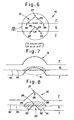
- optical information recording media 40 of a second aspect of the invention (second invention) is explained, based on Fig. 6 through Fig. 8.
- Fig. 6 is an enlarged plane view showing in enlargement the optical information recording media 40, and in particular a portion of a meandering land pre-pit 21 and a portion of a circular spot 9S of laser light 9 irradiating the media.
- land pre-pits 21 are formed in a portion of the pregroove 6 to protrude in an arc shape in the radial direction on the outer circumference side of the optical information recording media 40.
- the land pre-pits 21 of this invention are such that the distances L in and L out range between the shortest pit length, 3T, to twice this length (6T).
- the distances L in and L out be in the range from 3.36T to 5.22T.
- the distance L in be in the range from 3T to 4T, and more preferably still, in the range from 3.36T to 3.73T.
- the distance L out be in the range from 4T to 6T, and more preferably still, in the range from 4.85T to 5.22T.
- Fig. 7 is an enlarged plane view for a case in which a recorded pit 10 overlaps with a portion of a conventional meandering land pre-pit 8
- Fig. 8 is an enlarged plane view for a case in which a recorded pit 10 overlaps with a portion of a meandering land pre-pit 8 of this invention, showing in particular the state in which the laser light 9 is slightly shifted to the disc radial-direction center side (detracking).
- tracking of the laser light 9 ideally should involve movement of the center 9C along the center line 6C of the pregroove 6; but in actuality, as recording speeds are increased, the center 9C of the laser light 9 deviates from the center line 6C of the pregroove 6, and recorded pits 10 may be recorded.
- the distances L in and L out are within the range 3T to 6T.
- the inside edge portions 22 of the inside protruding portion 23 in particular are positioned closer to each other than in the case of conventional arc-shape land pre-pits 8, so that the area of encroachment of the land 7 (inside protruding portion 23) on the portion of the recorded pit 10 is smaller than in the prior art, and the effect exerted on the shape and size of the recorded pit 10 can be reduced.
- a land pre-pit 21 is positioned within the circular spot 9S of the laser light 9, then adjustment is possible depending on the state of the deposited film in this portion without being greatly affected by differences in the unrecorded optical depth in the range from ⁇ /8 to ⁇ /5 and without greatly affecting the RF signal, so that optimization is possible.
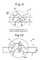
- Fig. 9 is an enlarged plane view showing in enlargement the optical information recording media 50, and in particular a portion of a meandering land pre-pit 21 and a portion of a circular spot 9S of laser light 9 irradiating this pre-pit.
- land pre-pits 21 are formed in a portion of the pregroove 6, protruding in an arc shape in the radial direction on the outer circumference side of the optical information recording media 50.
- the land pre-pits 21 of this invention are such that 0.40 ⁇ m ⁇ L in ⁇ 0.80 ⁇ m, and 0.40 ⁇ m ⁇ L out ⁇ 0.80 ⁇ m.
- the inside edge portions 22 of the inside protruding portion 23 and outside edge portions 24 of the outside protruding portion 25 of these land pre-pits 21 are positioned within the range of the circular spot 9S of the laser light 9.
- the land pre-pits 21 are positioned within the circular spot 9S of the laser light 9.
- optical information recording media 50 having land pre-pits 21 configured in this way, intensity differences due to diffraction of laser light at the land pre-pit portions 21 can be made clear and the accuracy of detection of land pre-pits 21 can be improved so that land pre-pit signals can be obtained; in addition, the effect on RF signals can be reduced, and fluctuations therein can be held below a prescribed level.
- the margin with respect to external disturbances is increased, and moreover the detection accuracy is improved, so that even if the land pre-pit 21 is in proximity to a recorded pit 10, the AR of the land pre-pit signal is maintained at 15% or higher and readout errors are avoided, while the RF signal fluctuation amount can be held to less than 1%.
- a land pre-pit 21 is positioned within the circular spot 9S of the laser light 9, then adjustment is possible depending on the state of the deposited film in this portion without being greatly affected by differences in the unrecorded optical depth in the range from ⁇ /8 to ⁇ /5 and without greatly affecting the RF signal, so that optimization is possible.
- optical information recording media 60 of a fourth aspect of this invention (fourth invention) is explained, based on Fig. 10 through Fig. 14.
- Fig. 10 is an enlarged plane view of a portion of a meandering land pre-pit 8 in the optical information recording media 60.
- Land pre-pits 8 are formed in circular arc shapes or elliptical arc shapes, similarly to those of the prior art shown in Fig. 20, in portions of the pregroove 6 protruding in an arc shape on the outside circumference side in the radial direction of the optical information recording media 60.
- a land pre-pit 8 is delineated by the inside arc-shape portion 62 extending in an arc shape from the pair of inside arc edge portions 61 on the left and right in the figure and by the outside arc-shape portion 64 extending in an arc shape from the outside arc-shape edge portions 63, and is formed protruding in a circular arc shape on the outside circumference side in the radial direction of the optical information recording media 60.
- the inside arc-shape portion 62 and outside arc-shape portion 64 are both based on an elliptical arc shape, and are formed in arc shapes by selecting the curve of a portion of an ellipse.
- the inside arc-shape portion 62 and outside arc-shape portion 64 can be designed based on a triangular shape, arc shape, trapezoidal shape, or other arbitrary shape or arbitrary curve.
- the other portions of the optical information recording media 60 are similar to those of the optical information recording media 1 shown in Fig. 15 through Fig. 18.
- the inside protrusion length in the radial direction on the arc inner side of a land pre-pit 8 (the distance from the additional line connecting the inside arc shape edge portions 61 on both sides to the additional line tangent to the inside arc-shape portion 62 at the most prominently protruding portion 65 of the circular arc of the inside arc-shape portion 62) is R in .
- the outside protrusion length in the radial direction on the arc outer side of a land pre-pit 8 (the distance from the additional line connecting the outside arc shape edge portions 63 on both sides to the additional line tangent to the outside arc-shape portion 64 at the most prominently protruding portion 66 of the circular arc of the outside arc-shape portion 64) is R out .
- the inner wall portion of a land pre-pit 8 in the substrate 2 has an inclination angle G of from 40 to 80°, and each of the above additional lines is drawn at the width at one-half the depth D of the land pre-pit 8 (the half-maximum width).
- the land pre-pits 8 of this invention be such that 0.120 ⁇ m ⁇ R in ⁇ 0.182 ⁇ m, and 0.100 ⁇ m ⁇ R out ⁇ 0.250 ⁇ m. This is explained below.
- the RF signal fluctuation amount must be held to at least less than 1%, and in addition the characteristics of the land pre-pits 8, that is, the AR (amplitude decrease rate index), must be maintained at 15% or higher.
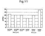
- Fig. 11 is a graph showing the relation of AR to R out and R in ; as indicated in the figure, R out does not greatly affect AR, and the influence of R in dominates.
- This invention (the fourth invention) was devised by discovering regularity between the design values for R in and R out (the meandering shape design values), the amount of RF signal fluctuation, the AR (amplitude decrease rate index), and other measured electrical signal values, and drawing graphs with R in and R out plotted on the vertical and horizontal axes.
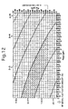
- Fig. 12 is a graph showing the range of RF signal fluctuation amounts and the range over which the AR is 15% or higher, plotting R out on the horizontal axis and R in on the vertical axis.
- the range over which AR is 15% or higher is indicated by an arrow on the R in axis
- RF signal fluctuation amounts are indicated in percentages (%) for regions delineated by arc-shape boundary lines.
- the range over which the AR is 15% or higher and the absolute value of RF signal fluctuations is 1% or less is 0.120 ⁇ m ⁇ R in ⁇ 0.182 ⁇ m and 0.100 ⁇ m ⁇ R out ⁇ 0.250 ⁇ m.
- Fig. 13 shows a case in which the design margins are expanded to stipulate that the AR be 18% or higher and that RF signal fluctuation amounts be less than 0.7%.
- Fig. 13 is a graph showing the range of RF signal fluctuation amounts and the range over which the AR is 18% or higher, plotting R out on the horizontal axis and R in on the vertical axis.
- the range over which the AR is 18% or higher and the absolute value of RF signal fluctuations is less than 0.7% is 0.140 ⁇ m ⁇ R in ⁇ 0.173 ⁇ m and 0.100 ⁇ m ⁇ R out ⁇ 0.192 ⁇ m.
- R in and R out shown in Fig. 13 the range in which the inside protruding length R in is greater than the outside protruding length R out (R out ⁇ R in ) is difficult to realize, considering the fabrication and moldability of the optical information recording media 60 and the stamper therefor; realistically, it is preferable that R in be at maximum approximately 0.156 ⁇ m, and that R in ⁇ R out .
- Fig. 14 is a graph showing the range of RF signal fluctuation amounts and the range over which the AR is 18% or higher, plotting R out on the horizontal axis and R in on the vertical axis.
- the range over which the AR is 18% or higher, the absolute value of RF signal fluctuations is less than 0.7%, and in addition R in is at maximum approximately 0.156 ⁇ m and R in ⁇ R out , is 0.140 ⁇ m ⁇ R in ⁇ 0.156 ⁇ m and 0.156 ⁇ m ⁇ R out ⁇ 0.192 ⁇ m.
- the RF signal and land pre-pit signal are expected to fluctuate according to the extent of this deviation; in order to reduce insofar as possible the influence of this detracking, it is preferable that 0.120 ⁇ m ⁇ R in ⁇ 0.130 ⁇ m and 0.180 ⁇ m ⁇ R out ⁇ 0.244 ⁇ m.
- the inside edge portions and outside edge portions of land pre-pits are positioned within the circular spot of the laser light, which is either recording light or reproduction light, so that laser light diffraction can be made clear and the accuracy of land pre-pit detection can be improved, readout errors can be avoided through reduction in errors for both land pre-pit signals and for RF signals, and the specific shape of land pre-pits can be designed to accommodate high optical information densities and high speeds.
- the distance L in between the pair of inside edge portions and the distance L out between the pair of outside edge portions of a land pre-pit are limited to the range 3T to 6T, so that the effect on recorded pits of even slight deviations in the laser light during recording or reproduction is reduced, errors can be reduced and readout errors avoided for both land pre-pit signals and for RF signals, and the specific shape of land pre-pits can be designed to accommodate high optical information densities and high speeds.
- the laser light diffraction can be made clear and the accuracy of detection of land pre-pits can be improved, errors can be reduced and readout errors avoided for both land pre-pit signals and for RF signals, and the specific shape of land pre-pits can be designed to accommodate high optical information densities and high speeds.
- the fourth invention by designing meandering land pre-pits so as to satisfy the conditions regarding the inside protruding length R in and outside protruding length R out of 0.120 ⁇ m ⁇ R in ⁇ 0.182 ⁇ m and 0.100 ⁇ m ⁇ R out ⁇ 0.250 ⁇ m, RF signal fluctuation amounts can be held to less than 1% and the land pre-pit signal AR can be maintained at 15% or higher, readout errors can be avoided, and the specific shape of land pre-pits can be designed to accommodate high optical information densities and high speeds.
Landscapes
- Optical Recording Or Reproduction (AREA)
- Optical Record Carriers And Manufacture Thereof (AREA)
Abstract
It is an object to provide optical information recording
media enabling the recording at high speeds and high densities,
such as onto DVD-R discs or similar, of optical information,
optimizing the shape of meandering land pre-pits 21,
increasing clearness of diffraction of laser light 9 by the
land pre-pits 21 to obtain a satisfactory land pre-pit signal,
and simultaneously reducing RF readout errors for recorded
pits and readout errors for land pre-pits 21, focusing on
optimization of the size of the inside protruding portion 23
and outside protruding portion 25 relative to the spot 9S of
the laser light 9 with respect to the shape and size of the
land pre-pits 21, and when e is the base of natural logarithms,
the media is characterized in that the inside edge portions 22
of the inside protruding portion 23 and the outside edge
portions 24 of the outside protruding portion 25 of the land
pre-pits 21 are positioned within the range of the spot
diameter E2 in the 1/e2 portion of the Gaussian energy
distribution of the spot 9S of laser light 9. Further, with
respect to the distance Lin between the two inside edge
portions 22 of the inside protruding portion 23 of the land
pre-pits 21, the distance Lout between the two outside edge
portions 24 of the outside protruding portion 25 of the land
pre-pits 21, and the basic length T expressing the lengths of
recorded pits, the media is further characterized in that the
distances Lin and Lout are in the range 3T to 6T; that 0.40 µm ≤
Lin ≤ 0.80 µm and 0.40 µm ≤ Lout ≤ 0.80 µm; and that, when the
inside protruding length in the radial direction on the inside
of the arc shape of land pre-pits 8 is Rin and the outside
protruding length is Rout, 0.120 µm ≤ Rin ≤ 0.182 µm and 0.100
µm ≤ Rout ≤ 0.250 µm.
Description
This invention relates to optical information recording
media, and in particular to optical information recording
media having an optical recording layer, comprising at least
light absorbing material or similar, and a metal film or other
light reflecting layer on a translucent substrate, and which
is capable of recording and reproduction at high density and
at high speed, using for example short-wavelength red laser
light of wavelength 630 to 670 nm or blue laser light of
wavelength 400 to 410 nm.
The specifications adopted for DVD-R (Digital Versatile
(or Video) Disc Writable) discs, capable of optical recording
of information at higher densities than the recordable CD-R
(Compact Disc Writable) discs which have in the past been
widely adopted as optical information recording media, are
different from the specifications for CD-R discs.
Differences include, for example, the fact that the
optical pickup uses short-wavelength red laser light of
wavelength 630 to 670 nm and an objective lens with a high
numerical aperture (NA) of 0.6 to 0.65.
In the prior art, in recordable CD-R discs the spiral-shape
pregroove, used as a tracking guide, is made to "wobble",
this wobble is frequency-modulated, and position information
called ATIP (Absolute Time In Pregroove) and other address
information is obtained.
On the other hand, in a DVD-R disc, in place of the above
ATIP, together with formation of the "wobble", land pre-pits
are formed in lands between the pregroove; by this means
address information and other sector information on the
optical information recording media is obtained.
When data bits (recording bits) are recorded in optical
information recording media in which such land pre-pits are
formed and are then reproduced, the above-described optical
pickup reads both the data pits and the land pre-pits, and
there is the problem that, depending on the relative
positional relationship between the data pits and land pre-pits,
errors may occur in read signals and reproduction may
become unstable.
Conventional optical information recording media with
land pre-pits is explained below, based on Fig. 15 through Fig.
24.
Fig. 15 is an enlarged plane view of principal portions
of conventional optical information recording media 1 and a
graph of the RF signals and land pre-pit signals thereof; Fig.
16 is a cross-sectional view along line XVI-XVI in Fig. 15;
Fig. 17 is a cross-sectional view along line XVII-XVII in Fig.
15; and Fig. 18 is a cross-sectional view along line XVIII-XVIII
in Fig. 15.
The optical information recording media 1 has a
translucent substrate 2, a light absorbing layer 3 (optical
recording layer) formed on the substrate 2, a light reflecting
layer 4 formed on the light absorbing layer 3, and a
protective layer 5 formed on the light reflecting layer 4.
A spiral-shape pregroove 6 is formed in the above
substrate 2. On the left and right of this pregroove are
positioned portions other than the pregroove 6, that is, lands
7. Land pre-pits 8 are formed at a prescribed period in the
lands 7, and address information and other sector information
is recorded.
As shown in Fig. 18, when the optical information
recording media 1 is irradiated with laser light 9 (recording
light, forming the circular spot 9S in Fig. 15), the light
absorbing layer 3 absorbs the energy of this laser light 9 and
so is heated, and thermal transformation occurs on the side of
the substrate 2 to form the recorded pit 10.
Fig. 15 mainly depicts the pregrooves 6, lands 7, land
pre-pits 8, and recorded pit 10, omitting the light reflecting
layer 5 and protective layer 5 of the optical information
recording media 1.
Further, by forming undulations ("wobbles", 6W) in the
pregroove 6 along the circumferential direction of the optical
information recording media, as shown in Fig. 15, Fig. 16, Fig.
17 and Fig. 18, rotation of the optical information recording
media can be synchronized with information recording and
readout, and tracking action can be secured during recording.
The substrate 2 and light absorbing layer 3 are in
contact at the first layer interface 11.
The light absorbing layer 3 and light reflecting layer 4
are in contact at the second layer interface 12.
The light reflecting layer 4 and protective layer 5 are
in contact at the third layer interface 13.
The translucent substrate 2 is formed primarily from a
resin with excellent shock resistance, and which is a material
with high transparency and with refractive index for laser
light in the range of, for example, 1.4 to 1.6 approximately;
for example, polycarbonate, glass plate, acrylic plate, epoxy
plate, or similar may be used.
The light absorbing layer 3 is a layer comprising light
absorbing material (light-absorption material) formed on the
substrate 2; upon irradiation with laser light 9, this layer
undergoes heating, fusion, sublimation, deformation, or
degeneration. This light absorbing layer 3 uniformly coating
the surface of the substrate 2 with a cyanine dye or similar,
dissolved in a solvent, using spin-coating or other means.
As the material used in the light absorbing layer 3, an
arbitrary optical recording material can be adopted, but an
optically absorptive organic dye is preferable.
The light reflecting layer 4 is a metal film, formed by
evaporation deposition, sputtering or similar means from for
example gold, silver, copper, aluminum, or an alloy comprising
any of these.
The protective layer 5 is formed from a resin having
excellent shock resistance, similar to the substrate 2. For
example, an ultraviolet-curing resin may be applied by a spin-coating
method and then cured by irradiation with ultraviolet
rays to form the layer.
As indicated by the graph in Fig. 15, upon irradiation
with laser light 9 as reproduction light, the RF signal (on
the left side in the figure) of a recorded pit 10 not adjacent
to a land pre-pit 8 is obtained at an appropriate level. Also,
a land pre-pit signal (in the center of the figure) for a land
pre-pit 8 not adjacent to a recorded pit 10 can also be
obtained at an appropriate level.
However, when a land pre-pit 8 and recorded pit 10 are
mutually adjacent in the radial direction of the optical
information recording media 1 in particular, there is the
problem that the level of the land pre-pit signal and the
level of the RF signal both either fall or rise (right side in
Fig. 15).
Specifically, in the case of a land pre-pit signal, the
signal amplitude decreases, and the AR (Aperture Ratio, an
index of the rate of decrease in amplitude) declines. The AR
is the ratio (as a percentage) of the land pre-pit signal in a
portion in which there is a maximum-length recorded pit 10 to
the land pre-pit signal in a portion with no recorded pit 10;
the DVD-R standard requires that the AR be 15% or higher.
Fluctuations in the RF signal may lead to RF readout
errors; the DVD-R standard requires, as a criterion for
fluctuation of RF signals, that RF readout errors be fewer
than 250.
The above-described problems occur both when the land
pre-pits shown in Fig. 19 are of circular shape, and when the
land pre-pits 8 are meandering, as shown in Fig. 20.
Fig. 21 is a graph showing RF readout errors in relation
to the amount of fluctuation in the RF signal in the case of
circular land pre-pits 8. Fig. 22 is a graph showing RF
readout errors in relation to the amount of fluctuation in the
RF signal in the case of meandering land pre-pits 8.
As indicated in the figures, compared with circular land
pre-pits 8, meandering land pre-pits 8 have a narrower margin
with respect to the amount of RF signal fluctuation resulting
in an error, and the optimal design range for such pre-pits
must be set strictly with respect to various optical pickup
types and spot dimensions, as well as angular fluctuations,
focal fluctuations, tracking fluctuations, and other
disturbances which readily occur at high speeds in particular.
Also, there is the further problem, regarding meandering
land pre-pits 8, that the extent or protrusion length on the
inside and outside of the arc portion of the meandering shape,
or the distance between arc end portions, cannot easily be set
in an appropriate combination for the inside and for the
outside.
The amount of RF signal fluctuation is the amount of
fluctuation in the level (when there is a land pre-pit 8
adjacent to the recorded pit 10) relative to the level when
there is no fluctuation (when there is no land pre-pit 8
adjacent to the recorded pit 10), in percent; in order for
there to be fewer than 250 RF readout errors, according to Fig.
22, the RF signal fluctuation amount for meandering land pre-pits
8 must be at least 1% (1% as an absolute value) or lower.
As described above, optimized design conditions to lower
the readout errors of land pre-pits 8 while simultaneously
lowering RF readout errors are required for meandering land
pre-pits 8 in particular, and it is necessary to stabilize the
RF signal fluctuation amount at less than 1% while maintaining
the AR (amplitude decrease rate index) of land pre-pits 8 at
15% or higher.
On the other hand, particularly in the case of optical
information recording media 1 on which circular land pre-pits
8 are formed, there is the problem that the RF signal
fluctuates with the optical depth in the light absorbing layer
3, and the extent of fluctuation is comparatively large.
Fig. 23 is a graph of RF signals and land pre-pit signals
for optical information recording media similar to that of Fig.
15, and is a graph of RF signals for which the unrecorded
optical depth is approximately λ/5.8 (in particular, signals
for 3T pits which are the shortest recorded pits 10, where T
is the basic length representing the length of recorded pits;
T=0.134 µm) and of land pre-pit signals.
Fig. 24 is a graph of RF signals for which the unrecorded
optical depth is approximately λ/6.2 (similarly, 3T pit
signals) and of land pre-pit signals in the same media. Here
λ is the wavelength of the laser light 9.
As shown in Fig. 23, when the unrecorded optical depth is
approximately λ/5.8, there is almost no effect of the land
pre-pit signal on the RF signal compared with the graph on the
left side in the figure in which the recorded pit 10 is
isolated, as is clear from the right side of the figure in
which the recorded pit 10 is adjacent to a land pre-pit 8, and
there is only slight fluctuation of the RF signal.
However, when as in Fig. 24 the unrecorded optical depth
is approximately λ/6.2, when a recorded pit 10 and a land pre-pit
8 are adjacent, the RF signal is affected by the land pre-pit
signal, and there is the problem that fluctuation of the
signal amplitude of the RF signal increases.
The unrecorded optical depth can be calculated from the
depth of the pregroove 6, the thickness of the dye on the land
7, the thickness of the dye in the pregroove 6, the refractive
index n of the dye and substrate 2, and other parameters; but
from the graphs of Fig. 23 and Fig. 24, when land pre-pits 8
are circular the extent of fluctuation in the RF signal is
seen to depend heavily on the depth of the pregroove 6 and on
the thickness of the dye in the deposited film state.
On the other hand, according to a discovery by the
inventors, a meandering land pre-pit 8 is not so greatly
influenced by differences in the unrecorded optical depth
compared with circular land pre-pits 8, and depending on the
deposited film state, optimization is possible without greatly
affecting the RF signal.
Further, when meandering land pre-pits 8 are adopted, if
the laser light 9 is shifted from the center direction
(detracked) of the optical information recording media 1
(disc) due to some external disturbance, because meandering
land pre-pits 8 generally protrude in an arc shape in the
outward radial direction of the disc, when a land pre-pit 8
and recorded pit 10 overlap a portion of the land pre-pit 8
encroaches into the recorded pit 10 and affects the shape and
size of the recorded pit, so that there is the problem that
the recorded pit 10 cannot attain the necessary size and a
satisfactory RF signal cannot easily be obtained.
Land pre-pits and pre-pits are described in Japanese
Patent Laid-open No. 9-17029, Japanese Patent Laid-open No. 9-326138,
and Japanese Patent Laid-open No. 2000-40261 and
elsewhere.
This invention was devised in light of the above problems,
and has as an object the provision of optical information
recording media, and in particular DVD-R discs, enabling
recording of optical information at high densities.
A further object of this invention is the provision of
optical information recording media in which the shape of
meandering land pre-pits is optimized, and address information
and other sector information on the optical information
recording media can be obtained satisfactorily.
A further object of this invention is the provision of
optical information recording media with optimal design
conditions set to reduce land pre-pit readout errors, while
simultaneously reducing the RF readout errors of recorded pits.
A further object of this invention is the provision of
optical information recording media enabling the stabilization
of RF signal fluctuation amounts up to approximately 1% with
respect to meandering land pre-pits in particular, while
maintaining a land pre-pit AR (amplitude decrease rate index)
of 15% or higher.
A further object of this invention is the provision of
optical information recording media enabling the stabilization
of RF signal fluctuation amounts up to approximately 1% even
in cases of recording at high speeds of for example four or
more times the conventional linear speed (3.5 m/sec), while
maintaining a land pre-pit AR (amplitude decrease rate index)
of 15% or higher.
A further object of this invention is the provision of
optical information recording media in which, by designing the
shape and/or the size of land pre-pits in an optimal relative
positional relationship with the energy distribution of the
laser light spot, enables acquisition of the land pre-pit
signal.
A further object of this invention is the provision of
optical information recording media which can further clarify
diffraction of laser light at land pre-pit portions, enabling
the acquisition of satisfactory land pre-pit signals.
A further object of this invention is the provision of
optical information recording media enabling optimization of
land pre-pit signals, without being greatly influenced by
differences in the unrecorded optical depth, and without the
state of the deposited film greatly influencing the RF signal.
A further object of this invention is the provision of
optical information recording media in which, by designing the
shape and/or the size of land pre-pits in relation to the
optimal relative size of recorded pits written by laser light,
the signals of the recorded pits and land pre-pits can both be
obtained satisfactorily.
A further object of this invention is the provision of
optical information recording media enabling acquisition of
the required RF signal, with minimal influence on recorded
pits, even when there is shifting from the center direction
(detracking) of laser light on the optical information
recording media (disc).
A further object of this invention is the provision of
optical information recording media in which, through choice
of an appropriate length for land pre-pits in the scanning
direction, land pre-pit signals can be obtained.
That is, this invention (the first invention) is optical
information recording media which, focusing on optimization of
the shape and/or the size of meandering land pre-pits, the
inside protruding portion and outside protruding portion, and
the size relative to the laser light spot, has a translucent
substrate on which are formed a pregroove and land pre-pits in
the lands on either side of the pregroove, an optical
recording layer provided on this substrate and enabling
recording by recording light, and a light reflecting layer
provided on this optical recording layer and which reflects
the above recording light, and which enables recording, by
irradiation with the above recording light of the above
optical recording layer through the above substrate, of
information which can be read optically; the optical
information recording media is characterized in that the above
land pre-pits are continuous along the above pregroove and
protrude in the radial direction of the above substrate, and
that, if e is the base of natural logarithms, then the inside
edge portion of the inside protruding portion and the outside
edge portion of the outside protruding portion of the above
land pre-pits are positioned within the range of the diameter
of the spot of the above recording light in the 1/e2 portion of
the Gaussian energy distribution of the spot.
The above inside edge portion and the above outside edge
portion of the above land pre-pits can be positioned so as to
converge toward the center position of the above spot due to
the above recording light. Hence the shape of meandering land
pre-pits can itself be substantially a triangular shape.
If the distance between the above two inside edge
portions of the above inside protruding portions of the above
land pre-pits is Lin, and the distance between the above two
outside edge portions of the above outside protruding portions
is Lout, then these distances Lin and Lout can be made smaller
than the above spot diameter within the range of the diameter
of the spot of the above recording light in the 1/e2 portion of
the Gaussian energy distribution of the spot.
Together with the above inside edge portion and outside
edge portion of the above land pre-pits, the inside maximum
protrusion portion of the above inside protruding portion, and
the outside maximum protrusion portion of the above outside
protruding portion, can be positioned within the range of the
above spot diameter of the above recording light in the 1/e2
portion of the Gaussian energy distribution of the spot.
The above inside edge portion and the above outside edge
portion can be positioned within the range of the diameter of
the spot of the above recording light in the 1/e portion of
the Gaussian energy distribution of the spot.
As a result of positioning such that the entirety of the
above land pre-pits converge toward the center position of the
above spot, the shape of meandering land pre-pits, which
generally protrude in an arc shape, can itself be
substantially a triangular shape. Of course, the above land
pre-pits can be made in a triangular shape, an arc shape, a
trapezoidal shape, or another arbitrary shape.
In optical information recording media of this invention
(the first invention), when e is the base of natural
logarithms (approximately 2.72), the inside edge portion of
the inside protruding portion and the outside edge portion of
the outside protruding portion of land pre-pits are positioned
to be within the range of the diameter of the spot of the
above recording light in the 1/e2 portion of the Gaussian
energy distribution of the spot, so that the diffraction state
of laser light irradiating a land pre-pit is satisfactory on
the land pre-pit inside and outside and the land pre-pit
signal can be more clearly acquired by the laser light, and
even when a recorded pit exists near a land pre-pit the effect
on the RF signal can be reduced.
Further, land pre-pit signals can be optimized without
being greatly affected by differences in unrecorded optical
depths, and depending on the deposited film state, without
greatly affecting the RF signal.
In this way, RF fluctuations can be stabilized at
approximately 1% during reproduction and the AR of land pre-pits
can be maintained at 15% or higher, so that readout
errors for RF signals and land pre-pits can be avoided, and
necessary sector information can be reliably obtained even
from DVD-R discs at high densities and high speeds.
Next, this invention (the second invention) is optical
information recording media which, focusing on optimization of
the shape and/or the size of meandering land pre-pits, the
inside protruding portion and outside protruding portion, and
the size relative to recorded pits, has a translucent
substrate on which are formed a pregroove and land pre-pits in
the lands on either side of the pregroove, an optical
recording layer provided on this substrate and enabling
recording of recorded pits by recording light, and a light
reflecting layer provided on this optical recording layer and
which reflects the above recording light, and which enables
recording, by irradiation with the above recording light of
the above optical recording layer through the above substrate,
of information which can be read optically; the optical
information recording media is characterized in that the above
land pre-pits are continuous along the above pregroove and
protrude in the radial direction of the above substrate, and
that, if Lin is the distance between the two inside edge
portions of inside protruding portions of the above land pre-pits,
Lout is the distance between the two outside edge
portions of outside protruding portions of the above land pre-pits,
and T is the basic length representing the length of the
above recorded pits, then the distances Lin and Lout are in the
range 3T to 6T.
The above distances Lin and Lout can be limited to the
range 3.36T to 5.22T.
The above distance Lin can be limited to the range 3T to
4T.
The above distance Lin can be limited to the range 3.36T
to 3.73T.
The above distance Lout can be limited to the range 4T to
6T.
The above distance Lout can be limited to the range 4.85T
to 5.22T.
The above land pre-pits can be formed in triangular
shapes, arc shapes, trapezoidal shapes, or other arbitrary
shapes.
In an optical information recording media of this
invention (the second invention), the distance between the two
inside edge portions of inside protruding portions of land
pre-pits Lin and the distance between the two outside edge
portions of outside protruding portions of land pre-pits Lout
are set in the range 3T to 6T, so that even in states in which
recorded pits having ten different lengths 3T, 4T, ..., 10T,
11T, 14T overlap with land pre-pits, the RF signal can be
obtained satisfactorily without exerting a critical influence
on the shape and/or size of recorded pits, and readout errors
for land pre-pit signals can also be reduced.
Next, this invention (the third invention) is optical
information recording media which, focusing on appropriate
ranges for the distance Lin between the two inside edge
portions of inside protruding portions of land pre-pits and
for the distance Lout between the two outside edge portions of
outside protruding portions of land pre-pits, has a
translucent substrate on which are formed a pregroove and land
pre-pits in the lands on either side of the pregroove, an
optical recording layer provided on this substrate and
enabling recording of recorded pits by recording light, and a
light reflecting layer provided on this optical recording
layer and which reflects the above recording light, and which
enables recording, by irradiation with the above recording
light of the above optical recording layer through the above
substrate, of information which can be read optically; the
optical information recording media is characterized in that,
when the distance between the two inside edge portions of the
above land pre-pits is Lin and the distance between the two
outside edge portions of the above land pre-pits is Lout, these
values are set such that 0.40 µm ≤ Lin ≤ 0.80 µm and 0.40 µm ≤
Lout ≤ 0.80 µm.
The above distances Lin and Lout can be set such that 0.45
µm ≤ Lin ≤ 0.50 µm and 0.65 µm ≤ Lout ≤ 0.70 µm.
The above land pre-pits can be formed in a meandering
shape.
With respect to the above land pre-pits, it is sufficient
that the distances Lin and Lout be in the above range, and so in
general the shape of meander-shape or meandering land pre-pits
which protrude in an arc shape may be a shape which is
substantially triangular. Of course the above land pre-pits
may be in a triangular shape, an arc shape, a trapezoidal
shape, or another arbitrary shape.
In optical information recording media of this invention
(the third invention), the conditions for the distances Lin and
Lout of 0.40 µm ≤ Lin ≤ 0.80 µm and 0.40 µm ≤ Lout ≤ 0.80 µm are
set, so that the diffraction state of laser light incident on
land pre-pits is satisfactory on the land pre-pit outside and
inside, a clear land pre-pit signal can be obtained using this
laser light, and even when a recorded pit exists near the land
pre-pit, the effect on the RF signal can be reduced.
Further, the land pre-pit signal can be optimized without
being greatly influenced by differences in unrecorded optical
depth, and depending on the deposited film state, without
greatly affecting the RF signal.
In this way, the RF fluctuation amount during
reproduction can be stabilized at approximately 1%, the land
pre-pit AR can be maintained at 15% or higher, readout errors
for RF signals and land pre-pits can be avoided, and necessary
sector information can be reliably obtained even from DVD-R
discs at high densities and high speeds.
Next, this invention (the fourth invention) is optical
information recording media which, focusing on the arc shape
of meandering land pre-pits, the disc radial-direction inside
protruding length on the inside of the arc and the radial-direction
outside protruding length on the outside of the arc,
has a translucent substrate on which are formed a pregroove
and land pre-pits in the lands on either side of the pregroove,
an optical recording layer provided on this substrate and
enabling recording by recording light, and a light reflecting
layer provided on this optical recording layer and which
reflects the above recording light, and which enables
recording, by irradiation with the above recording light of
the above optical recording layer through the above substrate,
of information which can be read optically; the optical
information recording media is characterized in that the above
land pre-pits are continuous along the above pregroove and
protrude in the radial direction of the above substrate in an
arc shape, and that, if the inside protrusion length in the
radial direction on the inside of the arc is Rin and the
outside protrusion length in the radial direction on the
outside of the arc is Rout, then 0.120 µm ≤ Rin ≤ 0.182 µm and
0.100 µm ≤ Rout ≤ 0.250 µm.
The above Rin and Rout can be set such that 0.140 µm ≤ Rin ≤
0.173 µm and 0.100 µm ≤ Rout ≤ 0.192 µm.
The above Rin and Rout can be set such that Rin ≤ Rout.
The above Rin and Rout can be set such that 0.140 µm ≤ Rin ≤
0.156 µm and 0.156 µm ≤ Rout ≤ 0.192 µm.
The above Rin and Rout can be set such that 0.120 µm ≤ Rin ≤
0.130 µm and 0.180 µm ≤ Rout ≤ 0.244 µm.
When the wavelength of the above recording light is λ,
the recording depth in the unrecorded state in the above
pregroove can be set to λ/8 to λ/5.
The above optical recording layer can comprise light
absorbing material capable of absorbing the above recording
light.
In optical information recording media of this invention
(the fourth invention), for the inside protrusion length in
the radial direction on the inside of the arc Rin and the
outside protrusion length in the radial direction on the
outside of the arc Rout, the values
0.120 µm ≤ Rin ≤ 0.182 µm
and
0.100 µm ≤ Rout ≤ 0.250 µm
are set, so that when a land pre-pit and a recorded pit
are adjacent, and/or when there is partial overlap, not only
is the outside protruding length Rout of the land pre-pit
stipulated, but the inside protruding length Rin is also
stipulated; hence the RF fluctuation during reproduction can
be stabilized at approximately 1%, the AR of land pre-pits 8
can be maintained at 15% or higher, readout errors for RF
signals and land pre-pits can be avoided, and necessary sector
information can be reliably obtained even from DVD-R discs at
high densities and high speeds.
Next, the optical information recording media 20 of a
first aspect of this invention (first invention) is explained
based on Fig. 1 through Fig. 3. In the following explanation,
portions similar to portions in Fig. 15 through Fig. 24
related to the prior art are assigned the same symbols, and
detailed descriptions thereof are omitted.
Fig. 1 is an enlarged plane view showing in enlargement
the optical information recording media 20 and in particular a
portion of a meandering land pre-pit 21 and a portion of a
circular spot 9S of laser light 9 irradiating same; the
Gaussian energy distribution of the circular spot 9S of laser
light 9 is also shown.
As shown in Fig. 1, a land pre-pit 21 is formed in a
portion of the pregroove 6 in an arc shape, protruding outward
in the radial direction of the optical information recording
media 20.
A land pre-pit 21 is delineated by the inside protruding
portion 23 which extends in substantially a triangular shape
from the pair of inside edge portions 22 on the left and right
in the figure, and by the outside protruding portion 25 which
extends in substantially a triangular shape from the outside
edge portions 24, and is formed so as to protrude in
substantially a triangular shape on the side of the land 7
from the pregroove 6 on the outside circumference in the
radial direction of the optical information recording media 20.
Substantially an isosceles triangle is formed between the
most prominently protruding edge portion 26 on the inside of
the inside protruding portion 23 and the pair of inside edge
portions 22.
Substantially an isosceles triangle is formed between the
most prominently protruding edge portion 27 on the outside of
the outside protruding portion 25 and the pair of outside edge
portions 24.
Of course, the inside protruding portion 23 and outside
protruding portion 25 can be designed based on the shapes of
arbitrary curves.
Other portions of the optical information recording media
20 are similar to those of the optical information recording
media 1 shown in Fig. 15 through Fig. 18.
The distance between the two inside edge portions 22 of
the inside triangular shape of the land pre-pit 21 is Lin.
The distance between the two outside edge portions 24 of
the outside triangular shape of the land pre-pit 21 is Lout.
Fig. 2 is a vertical cross-sectional view of the land
pre-pit 21, and as shown in the figure, the inside wall of the
land pre-pit 21 in the substrate 2 has an inclination angle G
of 40 to 80°, and the above distances Lin and Lout are defined
as the width at one-half the depth D of the land pre-pit 21
(the half-maximum width).
If the wavelength of the laser light 9 is λ, then for
design conditions in which the optical depth in the unrecorded
state in the pregroove 6 is from λ/8 to λ/5 and the track
pitch of the pregroove 6 is from 0.70 to 0.85 µm, the land
pre-pits 21 of this invention are such that the inside edge
portions 22 of the inside protruding portion 23 and the
outside edge portions 24 of the outside protruding portion 25
of a land pre-pit 21 are positioned within the range of the
spot diameter E2 which is the 1/e2 portion of the Gaussian
energy distribution of the circular spot 9S of the laser light
9, where e is the base of natural logarithms (approximately
2.72).
In other words, the distances Lin and Lout of land pre-pits
21 are made smaller than the spot diameter E2 in the effective
energy range, which is the 1/e2 portion of the Gaussian energy
distribution of the circular spot 9S of laser light 9.
Further, it is preferable that, with respect to the land
pre-pits 21, together with the inside edge portions 22 and
outside edge portions 24, the most prominently protruding
inside edge portion 26 of the inside protruding portion 23 and
the most prominently protruding outside edge portion 27 of the
outside protruding portion 25 be positioned within the spot
diameter E2 of the 1/e2 portion of the Gaussian energy
distribution of the circular spot 9S of laser light 9.
It is still more preferable that the inside edge portions
22 and outside edge portions 24 of land pre-pits 21, and also
the most prominently protruding inside edge portion 26 and the
most prominently protruding outside edge portion 27 be
positioned within the range of the spot diameter E1 of the 1/e
portion of the Gaussian energy distribution of the circular
spot 9S of laser light 9.
Whereas conventional meandering land pre-pits are not
positioned within the range of the circular spot 9S, but a
portion extends outside, in the case of the land pre-pits 21
of this invention the inside edge portions 22 and outside edge
portions 24 thereof are positioned so as to converge toward
the center position of the circular spot 9S of laser light 9.
In optical information recording media 20 having land
pre-pits 21 configured in this way, intensity differences due
to diffraction of laser light at the land pre-pit portions 21
can be made clear and the accuracy of detection of land pre-pits
21 can be improved so that land pre-pit signals can be
obtained; in addition, the effect on RF signals can be reduced,
and fluctuations therein can be held below a prescribed level.
Fig. 3 is an enlarged plane view illustrating the state
of irradiation with laser light 9 (circular spot 9S) of a land
pre-pit 21. When directing the circular spot 9S of the laser
light 9 onto a land pre-pit 21 to obtain a signal from the
land pre-pit 21, diffraction of the laser light 9 by the land
pre-pit 21 results in a clear difference above and below the
range of the circular spot 9S (in the spot upper range 9A and
spot lower range 9B), enhancing the detection accuracy, so
that even if the land pre-pit 21 is in proximity to a recorded
pit 10, the AR of the land pre-pit signal is maintained at 15%
or higher and readout errors are avoided, while the RF signal
fluctuation amount can be held to less than 1%.
Further, if a land pre-pit 21 is positioned within the
circular spot 9S of the laser light 9, then adjustment is
possible depending on the state of the deposited film in this
portion without being greatly affected by differences in the
unrecorded optical depth in the range from λ/8 to λ/5 and
without greatly affecting the RF signal, so that optimization
is possible.
In this invention, if land pre-pits 21 are positioned
within the circular spot 9S of the laser light 9, the shape of
the land pre-pits 21 can be chosen arbitrarily.
For example, Fig. 4 is an enlarged plane view showing
another example of a land pre-pit (land pre-pit 30); this land
pre-pit 30 protrudes in an arc shape in the outward radial
direction of the optical information recording media 20, and
the inside edge portions 22 and most prominently protruding
inside edge portion 26 of the inside protruding portion 23, as
well as the outside edge portions 24 and most prominently
protruding outside edge portion 27 of the outside protruding
portion 25, are positioned within the range of the circular
spot 9S.
Fig. 5 is an enlarged plane view showing still another
example of a land pre-pit (land pre-pit 31); this land pre-pit
31 protrudes in a trapezoidal shape in the outward radial
direction of the optical information recording media 20, and
the inside edge portions 22 and most prominently protruding
inside edge portion 26 of the inside protruding portion 23, as
well as the outside edge portions 24 and most prominently
protruding outside edge portion 27 of the outside protruding
portion 25, are positioned within the range of the circular
spot 9S.
Next, the optical information recording media 40 of a
second aspect of the invention (second invention) is explained,
based on Fig. 6 through Fig. 8.
Fig. 6 is an enlarged plane view showing in enlargement
the optical information recording media 40, and in particular
a portion of a meandering land pre-pit 21 and a portion of a
circular spot 9S of laser light 9 irradiating the media.
As shown in Fig. 6, in the optical information recording
media 40, similarly to the optical information recording media
20 of the first invention (Fig. 1), land pre-pits 21 are
formed in a portion of the pregroove 6 to protrude in an arc
shape in the radial direction on the outer circumference side
of the optical information recording media 40.
In this invention (the second invention), when the
wavelength of the laser light 9 is λ, then for design
conditions in which the optical depth in the unrecorded state
in the pregroove 6 is from λ/8 to λ/5 and the track pitch of
the pregroove 6 is from 0.70 to 0.85 µm, the land pre-pits 21
of this invention are such that the distances Lin and Lout range
between the shortest pit length, 3T, to twice this length (6T).
Further, it is preferable that the distances Lin and Lout
be in the range from 3.36T to 5.22T.
Also, it is preferable that the distance Lin be in the
range from 3T to 4T, and more preferably still, in the range
from 3.36T to 3.73T.
Also, it is preferable that the distance Lout be in the
range from 4T to 6T, and more preferably still, in the range
from 4.85T to 5.22T.
Even when, in optical information recording media 40
having such land pre-pits 21, a land pre-pit 21 overlaps with
a recorded pit 10, by maintaining the shape and size of the
recorded pit 10 at the necessary level the effect on the RF
signal is reduced and the fluctuation amount can be held
within a prescribed range; in addition, the accuracy of
detection of land pre-pits 21 can be improved, and land pre-pit
signals can be obtained.
Fig. 7 is an enlarged plane view for a case in which a
recorded pit 10 overlaps with a portion of a conventional
meandering land pre-pit 8, and Fig. 8 is an enlarged plane
view for a case in which a recorded pit 10 overlaps with a
portion of a meandering land pre-pit 8 of this invention,
showing in particular the state in which the laser light 9 is
slightly shifted to the disc radial-direction center side
(detracking).
As is shown in Fig. 7 and Fig. 8, tracking of the laser
light 9 ideally should involve movement of the center 9C along
the center line 6C of the pregroove 6; but in actuality, as
recording speeds are increased, the center 9C of the laser
light 9 deviates from the center line 6C of the pregroove 6,
and recorded pits 10 may be recorded.
As shown in Fig. 7, when land pre-pits 8 have an arc
shape, as a result of encroachment of the land 7 into the
center portion of a recorded pit 10, the normal, that is to
say designed, shape and size of the recorded pit cannot be
obtained, and a satisfactory RF signal cannot be obtained upon
reproduction, so that there is a high probability of readout
errors. This tendency is prominent in the case of recorded
pits 10 which are shorter than 3T or similar.
On the other hand, as shown in Fig. 8, in the case of the
land pre-pits 21 of this invention the distances Lin and Lout
are within the range 3T to 6T. Hence in the example shown,
the inside edge portions 22 of the inside protruding portion
23 in particular are positioned closer to each other than in
the case of conventional arc-shape land pre-pits 8, so that
the area of encroachment of the land 7 (inside protruding
portion 23) on the portion of the recorded pit 10 is smaller
than in the prior art, and the effect exerted on the shape and
size of the recorded pit 10 can be reduced.
Moreover, readout errors occur less readily during
reproduction even when detracking of the laser light 9 occurs.
If a land pre-pit 21 is positioned within the circular
spot 9S of the laser light 9, then adjustment is possible
depending on the state of the deposited film in this portion
without being greatly affected by differences in the
unrecorded optical depth in the range from λ/8 to λ/5 and
without greatly affecting the RF signal, so that optimization
is possible.
Next, the optical information recording media of a third
aspect of this invention (third invention) is explained, based
on Fig. 9.
Fig. 9 is an enlarged plane view showing in enlargement
the optical information recording media 50, and in particular
a portion of a meandering land pre-pit 21 and a portion of a
circular spot 9S of laser light 9 irradiating this pre-pit.
As shown in Fig. 9, in the optical information recording
media 50, similarly to the optical information recording media
20 of the first invention (Fig. 1) and the optical information
recording media 40 of the second invention (Fig. 6), land pre-pits
21 are formed in a portion of the pregroove 6, protruding
in an arc shape in the radial direction on the outer
circumference side of the optical information recording media
50.
In this invention (the third invention), when the
wavelength of the laser light 9 is λ, then for design
conditions in which the optical depth in the unrecorded state
in the pregroove 6 is from λ/8 to λ/5 and the track pitch of
the pregroove 6 is from 0.70 to 0.85 µm, the land pre-pits 21
of this invention are such that 0.40 µm ≤ Lin ≤ 0.80 µm, and
0.40 µm ≤ Lout ≤ 0.80 µm.
It is preferable that 0.45 µm ≤ Lin ≤ 0.50 µm and 0.65 µm
≤ Lout ≤ 0.70 µm.
That is, the inside edge portions 22 of the inside
protruding portion 23 and outside edge portions 24 of the
outside protruding portion 25 of these land pre-pits 21 are
positioned within the range of the circular spot 9S of the
laser light 9.
In other words, by limiting the distances Lin and Lout, the
land pre-pits 21 are positioned within the circular spot 9S of
the laser light 9.
Whereas conventional meandering land pre-pits are not
positioned within the range of the circular spot 9S, but a
portion extends outside, in the case of the land pre-pits 21
of this invention the inside edge portions 22 and outside edge
portions 24 thereof are positioned so as to converge toward
the center position of the circular spot 9S of laser light 9.
In optical information recording media 50 having land
pre-pits 21 configured in this way, intensity differences due
to diffraction of laser light at the land pre-pit portions 21
can be made clear and the accuracy of detection of land pre-pits
21 can be improved so that land pre-pit signals can be
obtained; in addition, the effect on RF signals can be reduced,
and fluctuations therein can be held below a prescribed level.
That is, when irradiating a land pre-pit 21 with laser
light 9 (the circular spot 9S), directing the circular spot 9S
of the laser light 9 onto the land pre-pit 21 to obtain a
signal from the land pre-pit 21, the margin with respect to
external disturbances is increased, and moreover the detection
accuracy is improved, so that even if the land pre-pit 21 is
in proximity to a recorded pit 10, the AR of the land pre-pit
signal is maintained at 15% or higher and readout errors are
avoided, while the RF signal fluctuation amount can be held to
less than 1%.
Further, if a land pre-pit 21 is positioned within the
circular spot 9S of the laser light 9, then adjustment is
possible depending on the state of the deposited film in this
portion without being greatly affected by differences in the
unrecorded optical depth in the range from λ/8 to λ/5 and
without greatly affecting the RF signal, so that optimization
is possible.
Next, the optical information recording media 60 of a
fourth aspect of this invention (fourth invention) is
explained, based on Fig. 10 through Fig. 14.
Fig. 10 is an enlarged plane view of a portion of a
meandering land pre-pit 8 in the optical information recording
media 60. Land pre-pits 8 are formed in circular arc shapes
or elliptical arc shapes, similarly to those of the prior art
shown in Fig. 20, in portions of the pregroove 6 protruding in
an arc shape on the outside circumference side in the radial
direction of the optical information recording media 60.
That is, a land pre-pit 8 is delineated by the inside
arc-shape portion 62 extending in an arc shape from the pair
of inside arc edge portions 61 on the left and right in the
figure and by the outside arc-shape portion 64 extending in an
arc shape from the outside arc-shape edge portions 63, and is
formed protruding in a circular arc shape on the outside
circumference side in the radial direction of the optical
information recording media 60.
The inside arc-shape portion 62 and outside arc-shape
portion 64 are both based on an elliptical arc shape, and are
formed in arc shapes by selecting the curve of a portion of an
ellipse. Of course, similarly to the first through third
inventions, the inside arc-shape portion 62 and outside arc-shape
portion 64 can be designed based on a triangular shape,
arc shape, trapezoidal shape, or other arbitrary shape or
arbitrary curve.
As in the first through third inventions, the other
portions of the optical information recording media 60 are
similar to those of the optical information recording media 1
shown in Fig. 15 through Fig. 18.
The inside protrusion length in the radial direction on
the arc inner side of a land pre-pit 8 (the distance from the
additional line connecting the inside arc shape edge portions
61 on both sides to the additional line tangent to the inside
arc-shape portion 62 at the most prominently protruding
portion 65 of the circular arc of the inside arc-shape portion
62) is Rin.
The outside protrusion length in the radial direction on
the arc outer side of a land pre-pit 8 (the distance from the
additional line connecting the outside arc shape edge portions
63 on both sides to the additional line tangent to the outside
arc-shape portion 64 at the most prominently protruding
portion 66 of the circular arc of the outside arc-shape
portion 64) is Rout.
However, similarly to the land pre-pit 21 shown in Fig. 2,
the inner wall portion of a land pre-pit 8 in the substrate 2
has an inclination angle G of from 40 to 80°, and each of the
above additional lines is drawn at the width at one-half the
depth D of the land pre-pit 8 (the half-maximum width).
In this invention (the fourth invention), when the
wavelength of the laser light 9 is λ, then for design
conditions in which the optical depth in the unrecorded state
in the pregroove 6 is from λ/8 to λ/5 and the track pitch of
the pregroove 6 is from 0.70 to 0.85 µm, it is preferable that
the land pre-pits 8 of this invention be such that 0.120 µm ≤
Rin ≤ 0.182 µm, and 0.100 µm ≤ Rout ≤ 0.250 µm. This is
explained below.
As stated above, in order to simultaneously reduce the RF
readout errors of recorded pits 10 and the readout errors of
land pre-pits 8 when employing meandering land pre-pits 8, the
RF signal fluctuation amount must be held to at least less
than 1%, and in addition the characteristics of the land pre-pits
8, that is, the AR (amplitude decrease rate index), must
be maintained at 15% or higher.
Fig. 11 is a graph showing the relation of AR to Rout and
Rin; as indicated in the figure, Rout does not greatly affect AR,
and the influence of Rin dominates.
As shown in Fig. 11, when the figure of AR=15% is taken
as a target, the value Rin=0.120 µm lies on the borderline of
optimal design conditions for land pre-pits 8.
This invention (the fourth invention) was devised by
discovering regularity between the design values for Rin and
Rout (the meandering shape design values), the amount of RF
signal fluctuation, the AR (amplitude decrease rate index),
and other measured electrical signal values, and drawing
graphs with Rin and Rout plotted on the vertical and horizontal
axes.
Fig. 12 is a graph showing the range of RF signal
fluctuation amounts and the range over which the AR is 15% or
higher, plotting Rout on the horizontal axis and Rin on the
vertical axis. Here, the range over which AR is 15% or higher
is indicated by an arrow on the Rin axis, and RF signal
fluctuation amounts are indicated in percentages (%) for
regions delineated by arc-shape boundary lines.
As indicated by the oblique lines in Fig. 12, the range
over which the AR is 15% or higher and the absolute value of
RF signal fluctuations is 1% or less is 0.120 µm ≤ Rin ≤ 0.182
µm and 0.100 µm ≤ Rout ≤ 0.250 µm.
As is clear from Fig. 11 and Fig. 12, the design value
Rin=0.120 µm, when targeting the value AR=15%, is on the
borderline of optimal design conditions for land pre-pits 8,
and there are concerns that the AR may fall below 15% due to
external disturbances arising from the specifications of the
land pre-pits 8 or due to high recording speeds.
Fig. 13 shows a case in which the design margins are
expanded to stipulate that the AR be 18% or higher and that RF
signal fluctuation amounts be less than 0.7%.
Similarly to Fig. 12, Fig. 13 is a graph showing the
range of RF signal fluctuation amounts and the range over
which the AR is 18% or higher, plotting Rout on the horizontal
axis and Rin on the vertical axis.
As indicated by the oblique lines in Fig. 13, the range
over which the AR is 18% or higher and the absolute value of
RF signal fluctuations is less than 0.7% is 0.140 µm ≤ Rin ≤
0.173 µm and 0.100 µm ≤ Rout ≤ 0.192 µm.
Of the design range for Rin and Rout shown in Fig. 13, the
range in which the inside protruding length Rin is greater than
the outside protruding length Rout (Rout<Rin) is difficult to
realize, considering the fabrication and moldability of the
optical information recording media 60 and the stamper
therefor; realistically, it is preferable that Rin be at
maximum approximately 0.156 µm, and that Rin≤Rout.
That is, similarly to Fig. 13, Fig. 14 is a graph showing
the range of RF signal fluctuation amounts and the range over
which the AR is 18% or higher, plotting Rout on the horizontal
axis and Rin on the vertical axis.
As indicated by the oblique lines in Fig. 14, the range
over which the AR is 18% or higher, the absolute value of RF
signal fluctuations is less than 0.7%, and in addition Rin is
at maximum approximately 0.156 µm and Rin≤Rout, is 0.140 µm ≤ Rin
≤ 0.156 µm and 0.156 µm ≤ Rout ≤ 0.192 µm.
When the circular spot 9S of the laser light 9 deviates
from the center direction of the optical information recording
media 60 (disc) due to some external disturbance and is
shifted from recorded pits 10 and land pre-pits 8 (detracking),
the RF signal and land pre-pit signal are expected to
fluctuate according to the extent of this deviation; in order
to reduce insofar as possible the influence of this detracking,
it is preferable that 0.120 µm ≤ Rin ≤ 0.130 µm and 0.180 µm ≤
Rout ≤ 0.244 µm.
Thus in consideration of the ease of manufacturing,
including the fabrication or molding of the optical
information recording media 60 or stamper therefor, even under
conditions in which margins are reduced due to external
disturbances during high-speed recording, an optimized design
is possible which adequately satisfies characteristics
required for the land pre-pit 8 AR (amplitude decrease rate
index) and fluctuations of the RF signals from recorded pits
10.
Thus according to this invention (the first invention),
the inside edge portions and outside edge portions of land
pre-pits are positioned within the circular spot of the laser
light, which is either recording light or reproduction light,
so that laser light diffraction can be made clear and the
accuracy of land pre-pit detection can be improved, readout
errors can be avoided through reduction in errors for both
land pre-pit signals and for RF signals, and the specific
shape of land pre-pits can be designed to accommodate high
optical information densities and high speeds.
Also, according to this invention (the second invention),
the distance Lin between the pair of inside edge portions and
the distance Lout between the pair of outside edge portions of
a land pre-pit are limited to the range 3T to 6T, so that the
effect on recorded pits of even slight deviations in the laser
light during recording or reproduction is reduced, errors can
be reduced and readout errors avoided for both land pre-pit
signals and for RF signals, and the specific shape of land
pre-pits can be designed to accommodate high optical
information densities and high speeds.
Also, according to this invention (the third invention),
by setting the conditions for the distances Lin and Lout of 0.40
µm ≤ Lin ≤ 0.80 µm and 0.40 µm ≤ Lout ≤ 0.80 µm, the laser light
diffraction can be made clear and the accuracy of detection of
land pre-pits can be improved, errors can be reduced and
readout errors avoided for both land pre-pit signals and for
RF signals, and the specific shape of land pre-pits can be
designed to accommodate high optical information densities and
high speeds.
Also, according to this invention (the fourth invention),
by designing meandering land pre-pits so as to satisfy the
conditions regarding the inside protruding length Rin and
outside protruding length Rout of 0.120 µm ≤ Rin ≤ 0.182 µm and
0.100 µm ≤ Rout ≤ 0.250 µm, RF signal fluctuation amounts can
be held to less than 1% and the land pre-pit signal AR can be
maintained at 15% or higher, readout errors can be avoided,
and the specific shape of land pre-pits can be designed to
accommodate high optical information densities and high speeds.
Claims (21)
- Optical information recording media, having:a translucent substrate on which are formed a pregroove and land pre-pits in the land portions positioned on the left and right of the pregroove;an optical recording layer, provided on the substrate, enabling recording by recording light; anda light reflecting layer, provided on the optical recording layer, which reflects said recording light,and enabling recording, by irradiation of said optical recording layer with said recording light through said substrate, of information which can be read optically, the optical information recording media being characterized in that,said land pre-pits are continuous along said pregroove and are made to protrude in the radial direction of said substrate, andwhen e is the base of natural logarithms, then the inside edge portions of the inside protruding portion and the outside edge portions of the outside protruding portion of said land pre-pits are positioned within the range of the spot diameter in the 1/e2 portion of the Gaussian energy distribution of the spot due to said recording light.
- The optical information recording media according to Claim 1, characterized in that said inside edge portions and said outside edge portions of said land pre-pits are positioned so as to converge toward the center position of said spot due to said recording light.
- The optical information recording media according to Claim 1, characterized in that, when for said land pre-pits Lin is the distance between said two inside edge portions of said inside protruding portion and Lout is the distance between said two outside edge portions of said outside protruding portion, these distances Lin and Lout are made smaller than said spot diameter in the 1/e2 portion of said Gaussian energy distribution of said spot due to said recording light.
- The optical information recording media according to Claim 1, characterized in that, for said land pre-pits, in addition to said inside edge portions and said outside edge portions, the most prominently protruding inside edge portion of said inside protruding portion and the most prominently protruding outside edge portion of said outside protruding portion are positioned within the range of said spot diameter in the 1/e2 portion of said Gaussian energy distribution of said spot due to said recording light.
- The optical information recording media according to Claim 1, characterized in that said inside edge portions and said outside edge portions of said land pre-pits are positioned within the range of the spot diameter in the 1/e portion of said Gaussian energy distribution of said spot due to said recording light.
- Optical information recording media, having:a translucent substrate on which are formed a pregroove and land pre-pits in the land portions positioned on the left and right of the pregroove;an optical recording layer, provided on the substrate, enabling recording of recorded pits by recording light; and,a light reflecting layer, provided on the optical recording layer, which reflects said recording light,and enabling recording, by irradiation of said optical recording layer with said recording light through said substrate, of information which can be read optically, the optical information recording media being characterized in that,said land pre-pits are continuous along said pregroove and are made to protrude in the radial direction of said substrate, andwhen Lin is the distance between two inside edge portions of the inside protruding portion of said land pre-pits, Lout is the distance between two outside edge portions of the outside protruding portion of said land pre-pits, and T is the basic length representing the length of said recorded pits, these distances Lin and Lout are within the range 3T to 6T.
- The optical information recording media according to Claim 6, characterized in that said distances Lin and Lout are in the range 3.36T to 5.22T.
- The optical information recording media according to Claim 6, characterized in that said distance Lin is in the range 3T to 4T.
- The optical information recording media according to Claim 6, characterized in that said distance Lin is in the range 3.36T to 3.73T.
- The optical information recording media according to Claim 6, characterized in that said distance Lout is in the range 4T to 6T.
- The optical information recording media according to Claim 6, characterized in that said distance Lout is in the range 4.85T to 5.22T.
- Optical information recording media, having:a translucent substrate on which are formed a pregroove and land pre-pits in the land portions positioned on the left and right of the pregroove;an optical recording layer, provided on the substrate, enabling recording by recording light; anda light reflecting layer, provided on the optical recording layer, which reflects said recording light,and enabling recording, by irradiation of said optical recording layer with said recording light through said substrate, of information which can be read optically, the optical information recording media being characterized in that,when Lin is the distance between two inside edge portions of said land pre-pits, and Lout is the distance between two outside edge portions of said land pre-pits, the distances Lin and Lout are such that 0.40 µm ≤ Lin ≤ 0.80 µm and 0.40 µm ≤ Lout ≤ 0.80 µm.
- The optical information recording media according to Claim 12, characterized in that said distances Lin and Lout are such that 0.45 µm ≤ Lin ≤ 0.50 µm and 0.65 µm ≤ Lout ≤ 0.70 µm.
- The optical information recording media according to Claim 12, characterized in that said land pre-pits are formed in a meandering shape.
- Optical information recording media, having:a translucent substrate on which are formed a pregroove and land pre-pits in the land portions positioned on the left and right of the pregroove;an optical recording layer, provided on the substrate, enabling recording by recording light; anda light reflecting layer, provided on the optical recording layer, which reflects said recording light,and enabling recording, by irradiation of said optical recording layer with said recording light through said substrate, of information which can be read optically, the optical information recording media being characterized in that,said land pre-pits are continuous along said pregroove and are made to protrude in an arc shape in the radial direction of said substrate, andwhen Rin is the inside protruding length in the radial direction on the inside of the arc shape and Rout is the outside protruding length in the radial direction on the outside of the arc shape, the lengths Rin and Rout are such that 0.120 µm ≤ Rin ≤ 0.182 µm and 0.100 µm ≤ Rout ≤ 0.250 µm.
- The optical information recording media according to Claim 15, characterized in that said lengths Rin and Rout are such that 0.140 µm ≤ Rin ≤ 0.173 µm and 0.100 µm ≤ Rout ≤ 0.192 µm.
- The optical information recording media according to Claim 15 or Claim 16, characterized in that said lengths Rin and Rout are such that Rin ≤ Rout.
- The optical information recording media according to Claim 15, characterized in that said lengths Rin and Rout are such that 0.140 µm ≤ Rin ≤ 0.156 µm and 0.156 µm ≤ Rout ≤ 0.192 µm.
- The optical information recording media according to Claim 15, characterized in that said lengths Rin and Rout are such that 0.120 µm ≤ Rin ≤ 0.130 µm and 0.180 µm ≤ Rout ≤ 0.244 µm.
- The optical information recording media according to Claim 15, characterized in that, when λ is the wavelength of said recording light, the optical depth in the unrecorded state in said pregroove is from λ/8 to λ/5.
- The optical information recording media according to Claim 15, characterized in that said optical recording layer comprises light absorbing material capable of absorbing said recording light.
Applications Claiming Priority (9)
| Application Number | Priority Date | Filing Date | Title |
|---|---|---|---|
| JP2002245481 | 2002-08-26 | ||
| JP2002245481 | 2002-08-26 | ||
| JP2002245497 | 2002-08-26 | ||
| JP2002245497 | 2002-08-26 | ||
| JP2002290975 | 2002-10-03 | ||
| JP2002290975 | 2002-10-03 | ||
| JP2003106113 | 2003-04-10 | ||
| JP2003106113 | 2003-04-10 | ||
| PCT/JP2003/010336 WO2004025631A1 (en) | 2002-08-26 | 2003-08-14 | Optical information recording medium |
Publications (2)
| Publication Number | Publication Date |
|---|---|
| EP1533797A1 true EP1533797A1 (en) | 2005-05-25 |
| EP1533797A4 EP1533797A4 (en) | 2009-04-01 |
Family
ID=31999407
Family Applications (1)
| Application Number | Title | Priority Date | Filing Date |
|---|---|---|---|
| EP03795223A Withdrawn EP1533797A4 (en) | 2002-08-26 | 2003-08-14 | Optical information recording medium |
Country Status (9)
| Country | Link |
|---|---|
| US (1) | US20060164965A1 (en) |
| EP (1) | EP1533797A4 (en) |
| JP (3) | JPWO2004025631A1 (en) |
| KR (1) | KR100687533B1 (en) |
| CN (1) | CN1324577C (en) |
| AU (1) | AU2003257848A1 (en) |
| CA (1) | CA2486806A1 (en) |
| TW (1) | TWI226630B (en) |
| WO (1) | WO2004025631A1 (en) |
Families Citing this family (5)
| Publication number | Priority date | Publication date | Assignee | Title |
|---|---|---|---|---|
| JP4539657B2 (en) * | 2007-01-18 | 2010-09-08 | ソニー株式会社 | Anti-reflection optical element |
| JP4818965B2 (en) * | 2007-03-19 | 2011-11-16 | 株式会社リコー | Optical recording medium |
| JP4796555B2 (en) * | 2007-08-16 | 2011-10-19 | 株式会社リコー | Single-sided double-layer optical recording medium |
| JP2011159376A (en) * | 2010-01-08 | 2011-08-18 | Panasonic Corp | Optical drive device |
| JP5496226B2 (en) | 2010-01-08 | 2014-05-21 | パナソニック株式会社 | Optical drive device |
Family Cites Families (18)
| Publication number | Priority date | Publication date | Assignee | Title |
|---|---|---|---|---|
| JPH09102143A (en) * | 1995-10-05 | 1997-04-15 | Nec Corp | optical disk |
| JP3201235B2 (en) * | 1995-10-23 | 2001-08-20 | 株式会社日立製作所 | Information recording medium, recording control information reproducing method and information recording / reproducing device |
| WO1997038527A1 (en) * | 1996-04-05 | 1997-10-16 | Matsushita Electric Industrial Co., Ltd. | Multimedia optical disk on which audio data of a plurality of channels and sub-video data together with time-varying image data, and device and method of reproducing the data |
| EP0818778B1 (en) * | 1996-07-09 | 2004-06-23 | Sharp Kabushiki Kaisha | Optical disc with dispersed wobble sections, manufacturing method and recording and reproducing method |
| JP3483709B2 (en) * | 1996-07-09 | 2004-01-06 | シャープ株式会社 | Optical recording medium, method for manufacturing the same, and method for reproducing optical information using the same |
| JPH1194577A (en) * | 1997-09-17 | 1999-04-09 | Matsushita Electric Ind Co Ltd | Optical disk having both practicality in car navigation and entertainment using high-quality images, and its reproducing apparatus |
| JP4372867B2 (en) * | 1998-10-23 | 2009-11-25 | パイオニア株式会社 | Optical disc and recording / reproducing apparatus |
| JP2000187887A (en) * | 1998-12-24 | 2000-07-04 | Ricoh Co Ltd | optical disk |
| JP2000353321A (en) * | 1999-04-08 | 2000-12-19 | Pioneer Electronic Corp | Optical recording medium and its manufacture |
| JP4042272B2 (en) * | 1999-10-20 | 2008-02-06 | ソニー株式会社 | Recording medium driving apparatus and tilt detection method |
| DE60118105T2 (en) * | 2000-01-14 | 2006-08-31 | Pioneer Corp. | Recordable optical disc and recording method |
| JP2001209945A (en) * | 2000-01-26 | 2001-08-03 | Sharp Corp | Optical disk and recording / reproducing device |
| JP4136280B2 (en) * | 2000-07-04 | 2008-08-20 | パイオニア株式会社 | Optical recording medium, manufacturing method and manufacturing apparatus |
| JP2002237102A (en) * | 2000-07-07 | 2002-08-23 | Tdk Corp | Optical recording medium and manufacturing method thereof |
| US6673411B2 (en) * | 2000-10-23 | 2004-01-06 | Mitsui Chemicals, Inc. | Optical recording medium |
| JP2002208187A (en) * | 2000-11-13 | 2002-07-26 | Nikon Corp | Optical information recording medium, stamper, exposure apparatus, and method of manufacturing stamper |
| JP2002237101A (en) * | 2000-12-08 | 2002-08-23 | Mitsubishi Chemicals Corp | Optical recording medium |
| JP2002304772A (en) * | 2001-04-05 | 2002-10-18 | Fuji Photo Film Co Ltd | Optical recording medium |
-
2003
- 2003-08-14 EP EP03795223A patent/EP1533797A4/en not_active Withdrawn
- 2003-08-14 TW TW092122402A patent/TWI226630B/en not_active IP Right Cessation
- 2003-08-14 US US10/526,162 patent/US20060164965A1/en not_active Abandoned
- 2003-08-14 KR KR1020047020827A patent/KR100687533B1/en not_active Expired - Fee Related
- 2003-08-14 JP JP2004571934A patent/JPWO2004025631A1/en not_active Withdrawn
- 2003-08-14 CN CNB038198851A patent/CN1324577C/en not_active Expired - Fee Related
- 2003-08-14 AU AU2003257848A patent/AU2003257848A1/en not_active Abandoned
- 2003-08-14 CA CA002486806A patent/CA2486806A1/en not_active Abandoned
- 2003-08-14 WO PCT/JP2003/010336 patent/WO2004025631A1/en not_active Ceased
-
2008
- 2008-09-26 JP JP2008247104A patent/JP2009043401A/en not_active Withdrawn
- 2008-09-26 JP JP2008247105A patent/JP4692974B2/en not_active Expired - Fee Related
Also Published As
| Publication number | Publication date |
|---|---|
| JP4692974B2 (en) | 2011-06-01 |
| HK1108762A1 (en) | 2008-05-16 |
| WO2004025631A1 (en) | 2004-03-25 |
| CN1324577C (en) | 2007-07-04 |
| CN1679089A (en) | 2005-10-05 |
| TWI226630B (en) | 2005-01-11 |
| AU2003257848A1 (en) | 2004-04-30 |
| CA2486806A1 (en) | 2004-03-25 |
| JPWO2004025631A1 (en) | 2006-01-12 |
| KR20050034649A (en) | 2005-04-14 |
| KR100687533B1 (en) | 2007-02-27 |
| HK1105828A1 (en) | 2008-02-22 |
| US20060164965A1 (en) | 2006-07-27 |
| EP1533797A4 (en) | 2009-04-01 |
| HK1108761A1 (en) | 2008-05-16 |
| JP2009043401A (en) | 2009-02-26 |
| JP2008305555A (en) | 2008-12-18 |
| HK1081716A1 (en) | 2006-05-19 |
| TW200407881A (en) | 2004-05-16 |
Similar Documents
| Publication | Publication Date | Title |
|---|---|---|
| EP1158504B1 (en) | Rewritable compact disk and method for manufacturing the same | |
| CN100399427C (en) | Optical disk, its manufacturing method, and recording and reproducing device | |
| US9412407B2 (en) | Multi-stack optical storage medium | |
| JP4692974B2 (en) | Optical information recording medium | |
| US6721265B1 (en) | High-density optical information recording medium and a substrate and a stamper for the manufacture thereof | |
| KR100939850B1 (en) | Optical information recording medium, optical measuring method thereof, and optical information recording / reproducing method | |
| JP2000040261A (en) | Optical information recording medium | |
| CN100452187C (en) | Optical information recording medium | |
| US20160343398A1 (en) | Multi-stack optical storage mediu | |
| JP2985100B2 (en) | Optical information recording medium and recording method thereof | |
| HK1108761B (en) | Optical information recording medium | |
| HK1105828B (en) | Optical information recording medium | |
| HK1108762B (en) | A recording medium for optical information | |
| JP2002237100A (en) | Optical recording medium | |
| JP3964357B2 (en) | Recording / reproducing method of phase change type optical information recording medium | |
| US20080068977A1 (en) | Information storage medium and disk apparatus | |
| JP2001093189A (en) | Multilayer optical disk and recording / reproducing method thereof | |
| JP2004030854A (en) | Stamper for optical information recording medium and method for producing the same | |
| JP2002237101A (en) | Optical recording medium | |
| KR20010009503A (en) | Optical recording medium | |
| HK1074694B (en) | Optical disk, method for producing the same, and recording and reproducing apparatus | |
| WO2010106972A1 (en) | Optical information recording medium | |
| JP2002157789A (en) | Optical information media | |
| JP2000048399A (en) | Phase change optical disk media |
Legal Events
| Date | Code | Title | Description |
|---|---|---|---|
| PUAI | Public reference made under article 153(3) epc to a published international application that has entered the european phase |
Free format text: ORIGINAL CODE: 0009012 |
|
| 17P | Request for examination filed |
Effective date: 20050222 |
|
| AK | Designated contracting states |
Kind code of ref document: A1 Designated state(s): AT BE BG CH CY CZ DE DK EE ES FI FR GB GR HU IE IT LI LU MC NL PT RO SE SI SK TR |
|
| AX | Request for extension of the european patent |
Extension state: AL LT LV MK |
|
| DAX | Request for extension of the european patent (deleted) | ||
| A4 | Supplementary search report drawn up and despatched |
Effective date: 20090304 |
|
| 17Q | First examination report despatched |
Effective date: 20090612 |
|
| STAA | Information on the status of an ep patent application or granted ep patent |
Free format text: STATUS: THE APPLICATION IS DEEMED TO BE WITHDRAWN |
|
| 18D | Application deemed to be withdrawn |
Effective date: 20091023 |