JP4372867B2 - Optical disc and recording / reproducing apparatus - Google Patents
Optical disc and recording / reproducing apparatus Download PDFInfo
- Publication number
- JP4372867B2 JP4372867B2 JP30196598A JP30196598A JP4372867B2 JP 4372867 B2 JP4372867 B2 JP 4372867B2 JP 30196598 A JP30196598 A JP 30196598A JP 30196598 A JP30196598 A JP 30196598A JP 4372867 B2 JP4372867 B2 JP 4372867B2
- Authority
- JP
- Japan
- Prior art keywords
- groove
- land
- predetermined
- light
- recording
- Prior art date
- Legal status (The legal status is an assumption and is not a legal conclusion. Google has not performed a legal analysis and makes no representation as to the accuracy of the status listed.)
- Expired - Fee Related
Links
Images


Classifications
-
- G—PHYSICS
- G11—INFORMATION STORAGE
- G11B—INFORMATION STORAGE BASED ON RELATIVE MOVEMENT BETWEEN RECORD CARRIER AND TRANSDUCER
- G11B7/00—Recording or reproducing by optical means, e.g. recording using a thermal beam of optical radiation by modifying optical properties or the physical structure, reproducing using an optical beam at lower power by sensing optical properties; Record carriers therefor
- G11B7/007—Arrangement of the information on the record carrier, e.g. form of tracks, actual track shape, e.g. wobbled, or cross-section, e.g. v-shaped; Sequential information structures, e.g. sectoring or header formats within a track
-
- G—PHYSICS
- G11—INFORMATION STORAGE
- G11B—INFORMATION STORAGE BASED ON RELATIVE MOVEMENT BETWEEN RECORD CARRIER AND TRANSDUCER
- G11B27/00—Editing; Indexing; Addressing; Timing or synchronising; Monitoring; Measuring tape travel
- G11B27/10—Indexing; Addressing; Timing or synchronising; Measuring tape travel
- G11B27/19—Indexing; Addressing; Timing or synchronising; Measuring tape travel by using information detectable on the record carrier
- G11B27/24—Indexing; Addressing; Timing or synchronising; Measuring tape travel by using information detectable on the record carrier by sensing features on the record carrier other than the transducing track ; sensing signals or marks recorded by another method than the main recording
-
- G—PHYSICS
- G11—INFORMATION STORAGE
- G11B—INFORMATION STORAGE BASED ON RELATIVE MOVEMENT BETWEEN RECORD CARRIER AND TRANSDUCER
- G11B7/00—Recording or reproducing by optical means, e.g. recording using a thermal beam of optical radiation by modifying optical properties or the physical structure, reproducing using an optical beam at lower power by sensing optical properties; Record carriers therefor
- G11B7/004—Recording, reproducing or erasing methods; Read, write or erase circuits therefor
- G11B7/005—Reproducing
- G11B7/0053—Reproducing non-user data, e.g. wobbled address, prepits, BCA
-
- G—PHYSICS
- G11—INFORMATION STORAGE
- G11B—INFORMATION STORAGE BASED ON RELATIVE MOVEMENT BETWEEN RECORD CARRIER AND TRANSDUCER
- G11B7/00—Recording or reproducing by optical means, e.g. recording using a thermal beam of optical radiation by modifying optical properties or the physical structure, reproducing using an optical beam at lower power by sensing optical properties; Record carriers therefor
- G11B7/007—Arrangement of the information on the record carrier, e.g. form of tracks, actual track shape, e.g. wobbled, or cross-section, e.g. v-shaped; Sequential information structures, e.g. sectoring or header formats within a track
- G11B7/00718—Groove and land recording, i.e. user data recorded both in the grooves and on the lands
-
- G—PHYSICS
- G11—INFORMATION STORAGE
- G11B—INFORMATION STORAGE BASED ON RELATIVE MOVEMENT BETWEEN RECORD CARRIER AND TRANSDUCER
- G11B7/00—Recording or reproducing by optical means, e.g. recording using a thermal beam of optical radiation by modifying optical properties or the physical structure, reproducing using an optical beam at lower power by sensing optical properties; Record carriers therefor
- G11B7/24—Record carriers characterised by shape, structure or physical properties, or by the selection of the material
- G11B7/2407—Tracks or pits; Shape, structure or physical properties thereof
- G11B7/24073—Tracks
- G11B7/24079—Width or depth
-
- G—PHYSICS
- G11—INFORMATION STORAGE
- G11B—INFORMATION STORAGE BASED ON RELATIVE MOVEMENT BETWEEN RECORD CARRIER AND TRANSDUCER
- G11B7/00—Recording or reproducing by optical means, e.g. recording using a thermal beam of optical radiation by modifying optical properties or the physical structure, reproducing using an optical beam at lower power by sensing optical properties; Record carriers therefor
- G11B7/24—Record carriers characterised by shape, structure or physical properties, or by the selection of the material
- G11B7/2407—Tracks or pits; Shape, structure or physical properties thereof
- G11B7/24085—Pits
-
- G—PHYSICS
- G11—INFORMATION STORAGE
- G11B—INFORMATION STORAGE BASED ON RELATIVE MOVEMENT BETWEEN RECORD CARRIER AND TRANSDUCER
- G11B2220/00—Record carriers by type
- G11B2220/20—Disc-shaped record carriers
- G11B2220/21—Disc-shaped record carriers characterised in that the disc is of read-only, rewritable, or recordable type
- G11B2220/215—Recordable discs
- G11B2220/216—Rewritable discs
-
- G—PHYSICS
- G11—INFORMATION STORAGE
- G11B—INFORMATION STORAGE BASED ON RELATIVE MOVEMENT BETWEEN RECORD CARRIER AND TRANSDUCER
- G11B2220/00—Record carriers by type
- G11B2220/20—Disc-shaped record carriers
- G11B2220/21—Disc-shaped record carriers characterised in that the disc is of read-only, rewritable, or recordable type
- G11B2220/215—Recordable discs
- G11B2220/218—Write-once discs
-
- G—PHYSICS
- G11—INFORMATION STORAGE
- G11B—INFORMATION STORAGE BASED ON RELATIVE MOVEMENT BETWEEN RECORD CARRIER AND TRANSDUCER
- G11B2220/00—Record carriers by type
- G11B2220/20—Disc-shaped record carriers
- G11B2220/25—Disc-shaped record carriers characterised in that the disc is based on a specific recording technology
- G11B2220/2537—Optical discs
- G11B2220/2562—DVDs [digital versatile discs]; Digital video discs; MMCDs; HDCDs
-
- G—PHYSICS
- G11—INFORMATION STORAGE
- G11B—INFORMATION STORAGE BASED ON RELATIVE MOVEMENT BETWEEN RECORD CARRIER AND TRANSDUCER
- G11B7/00—Recording or reproducing by optical means, e.g. recording using a thermal beam of optical radiation by modifying optical properties or the physical structure, reproducing using an optical beam at lower power by sensing optical properties; Record carriers therefor
- G11B7/08—Disposition or mounting of heads or light sources relatively to record carriers
- G11B7/09—Disposition or mounting of heads or light sources relatively to record carriers with provision for moving the light beam or focus plane for the purpose of maintaining alignment of the light beam relative to the record carrier during transducing operation, e.g. to compensate for surface irregularities of the latter or for track following
- G11B7/0943—Methods and circuits for performing mathematical operations on individual detector segment outputs
Description
【0001】
【発明の属する技術分野】
本発明は、情報の書き込みが可能な光ディスク等の記録再生媒体と、その記録再生媒体を用いる記録再生装置に関するものである。
【0002】
【従来の技術】
従来、この種の記録再生媒体として、映像や音声、コンピュータデータ等のマルチメディア情報を高密度記録することが可能なDVD(デジタルビデオディスク又はデジタルバーサタイルディスク)が知られている。
【0003】
また、DVDには、先駆けて普及した再生専用のDVD−ROMのほか、記録再生が可能なDVD−R(追記型DVD)と、再書き込みが可能な記録再生型のDVD−RWが知られている。
【0004】
DVD−RとDVD−RWでは、グルーブ(Groove)に情報を高精度且つ高密度で記録するために、物理フォーマットとして、グルーブ間のランド(Land)に、予めアドレス等の各種情報が設定されたランドプリピット(Land pre-pit)と呼ばれるピットを形成しておく方式が提案されている(特開平9−17029号公報)。
【0005】
すなわち、この方式のDVD−RとDVD−RWは、ランドプリピットがグルーブに隣接して形成されている。このため、グルーブ上に光スポットを位置づけて走査すると、ランドプリピット上にも光スポットが入射する状態が生じることとなり、ランドプリピットからの反射光を光検出器などで検出することで、アドレス等の各種情報を有する検出信号を生成できるようになっている。
【0006】
【発明が解決しようとする課題】
ところで、上記方式を採用するDVD−RとDVD−RWでは、ランドプリピットがグルーブに隣接して形成されているため、光スポットをグルーブ上に位置づけて走査すると、光スポットがランドプリピットに入射するときには、必然的にグルーブにも入射することとなる。
【0007】
したがって、上記の反射光には、ランドプリピットからの反射光だけでなくグルーブからの反射光が含まれることとなり、光検出器等から出力される検出信号にも、ランドプリピットからの反射光成分だけでなくグルーブからの反射光成分が含まれることになる。
【0008】
このため、ランドプリピットからの反射光成分に対してグルーブからの反射光成分が雑音として作用し、検出信号中からランドプリピットの情報を高精度で検出することが困難となる場合が考えられる。
【0009】
また、これとは逆に、グループに記録されている情報を上記の光スポットによる走査で読み取る場合には、ランドプリピットからの反射光の光量に較べて、グルーブからの反射光の光量変化が小さいと、グルーブからの反射光成分に対してランドプリピットからの反射光成分が雑音として作用し、上記の検出信号中からグルーブの情報を高精度で検出することが困難となる場合が考えられる。
【0010】
このように、グルーブとランドプリピットで反射されるそれぞれの反射光の光量が適切でないと、グルーブの情報とランドプリピットの情報を最適状態で検出することができなくなり、ひいては、高精度且つ高密度の記録・再生にとって阻害要因となることが考えられる。
【0011】
しかしながら、従来は、このような発症原因と最適化に関する十分な研究がなされていたとはいえなかった。
【0012】
本発明は、このような新たな課題を提起してなされたものであり、グルーブとランドプリピット及び光スポットに関する相互間での最適条件を満足する構造を有して高精度且つ高密度での記録再生を安定的に実現し得る記録再生媒体と、その記録再生媒体を用いる記録再生装置を提供することを目的とするものである。
【0013】
【課題を解決するための手段】
請求項1に記載の発明は、所定のトラックピッチで形成されたグルーブ及びランドと、所定の開口数(NA)の対物レンズで収束された所定波長(λ)のスポット光により前記グルーブの走査される方向に沿って所定間隔で前記ランドに形成されたランドプリピットとを有し、情報記録又は情報再生の際に前記グルーブに位置合わせして照射される前記スポット光により前記グルーブと共に前記ランドプリピットが走査される情報記録媒体である光ディスクにおいて、前記グルーブの前記走査される方向に対して略直交する方向におけるグルーブ幅(Gw)と、前記各々のランドプリピットの前記走査される方向におけるプリピット長(Lp)が、Gw/(λ/NA)=0.2093{Lp/(λ/NA)} 2 −0.4342Lp/(λ/NA)+0.332の関係を満たしていること、を特徴とする。
請求項2に記載の発明は、所定のトラックピッチで形成されたグルーブ及びランドと、所定の開口数(NA)の対物レンズで収束された所定波長(λ)のスポット光により前記グルーブの走査される方向に沿って所定間隔で前記ランドに形成されたランドプリピットとを有し、情報記録又は情報再生の際に前記グルーブに位置合わせして照射される前記スポット光により前記グルーブと共に前記ランドプリピットが走査される情報記録媒体である光ディスクにおいて、前記グルーブの前記走査される方向に対して略直交する方向におけるグルーブ幅(Gw)と、前記各々のランドプリピットの前記走査される方向におけるプリピット長(Lp)と、前記グルーブと前記ランドとの厚み方向のグルーブ深さ(Gd;単位μm)が、Gw/(λ/NA)≧0.2093{Lp/(λ/NA)} 2 −0.4342Lp/(λ/NA)+0.332−(−2.64Gd+0.1276)且つ、Gw/(λ/NA)≦0.2093{Lp/(λ/NA)} 2 −0.4342Lp/(λ/NA)+0.332+(−4.48Gd+0.2112)の関係を満たしていること、を特徴とする。
【0014】
請求項3に記載の発明は、所定のトラックピッチで形成されたグルーブ及びランドと、所定波長(λ)のスポット光により前記グルーブの走査される方向に沿って所定間隔で前記ランドに形成されたランドプリピットとを有し、前記グルーブに位置合わせして照射される前記スポット光により前記グルーブと共に前記ランドプリピットが走査される情報記録媒体である光ディスクに対して、情報記録又は情報再生を行う記録再生装置において、前記所定波長(λ)の光を射出する光源と、前記光源からの光を収束して前記スポット光を生じさせる、所定開口数(NA)の対物レンズとを有し、前記波長(λ)と開口数(NA)は、前記グルーブの前記走査の方向に対して略直交する方向におけるグルーブ幅(Gw)と、前記各々のランドプリピットの前記走査の方向におけるプリピット長(Lp)に対して、Gw/(λ/NA)=0.2093{Lp/(λ/NA)} 2 −0.4342Lp/(λ/NA)+0.332の関係に設定されていること、を特徴とする。
請求項4に記載の発明は、所定のトラックピッチで形成されたグルーブ及びランドと、所定波長(λ)のスポット光により前記グルーブの走査される方向に沿って所定間隔で前記ランドに形成されたランドプリピットとを有し、前記グルーブに位置合わせして照射される前記スポット光により前記グルーブと共に前記ランドプリピットが走査される情報記録媒体である光ディスクに対して、情報記録又は情報再生を行う記録再生装置において、前記所定波長(λ)の光を射出する光源と、前記光源からの光を収束して前記スポット光を生じさせる、所定開口数(NA)の対物レンズとを有し、前記波長(λ)と開口数(NA)は、前記グルーブの前記走査の方向に対して略直交する方向におけるグルーブ幅(Gw)と、前記各々のランドプリピットの前記走査の方向におけるプリピット長(Lp)と、前記グルーブと前記ランドとの厚み方向のグルーブ深さ(Gd;単位μm)に対して、Gw/(λ/NA)≧0.2093{Lp/(λ/NA)} 2 −0.4342Lp/(λ/NA)+0.332−(−2.64Gd+0.1276)且つ、Gw/(λ/NA)≦0.2093{Lp/(λ/NA)} 2 −0.4342Lp/(λ/NA)+0.332+(−4.48Gd+0.2112)の関係に設定されていること、を特徴とする。
【0017】
【発明の実施の形態】
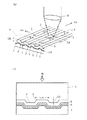
以下、本発明の実施の形態を図面を参照して説明する。尚、光ディスクであるDVD−RとDVD−RWの実施形態について説明する。図1(a)は、本実施形態のDVD−RとDVD−RWの基本構造を模式的に示す斜視図、図1(b)は、本実施形態のDVD−RとDVD−RWのラジアル方向の縦断面構造を模式的に示す断面図である。
【0018】
図1(a)において、DVD−RとDVD−RW(以下、これらを光ディスクと総称する)の情報が書き込まれる領域、すなわち、リードインとリードアウト及びプログラム領域には、グルーブ1が、本光ディスクの回転中心に設けられている所謂クランピングエリア(図示略)を中心とする螺旋状の連続したトラックに沿って、又はクランピングエリアを中心とする同心円状の多数トラックに沿って、一定のトラックピッチで形成されている。
【0019】
更に、上記の螺旋状のトラックと同心円状のトラックの何れのトラックに沿って形成される場合にも、光走査方向θtに対して略直交する方向(ラジアル方向)θrの縦断面を見ると、同図(b)に示すように、多数のグルーブ1が一定のトラックピッチで形成された構造となっている。
【0020】
グルーブ1のそれぞれの両側には、ラジアル方向θrにおける各グルーブ1の間を分離するためのランド2が併設されている。また、ランド2には、物理フォーマットとして、アドレス等の各種情報が予め設定されたランドプリピット3が、線走査方向θtに沿って所定間隔で形成されている。
【0021】
グルーブ1とランド2及びランドプリピット3は、ポリカーボネート等の透明樹脂を材料とする透明基板4上に形成され、グルーブ1とランド2及びランドプリピット3の下面には、有機色素や無機金属を材料とする記録層5と、アルミ蒸着や金蒸着による反射層6が積層され、更に、反射層6の下面にはUV硬化性樹脂(紫外線硬化性樹脂)等を材料とする保護層7が形成されている。
【0022】
そして、記録又は再生のための光が、光ピックアップ装置等に設けられている対物レンズ8を通して、透明基板4側からグルーブ1上にスポット照射されるようになっている。
【0023】
かかる構造の光ディスクにおいて、グルーブ1のラジアル方向θrにおける幅(以下、グルーブ幅という)Gwと、ランドプリピット3の線走査方向θtにおける長さ(以下、プリピット長という)Lpと、ランド2の底面からグルーブ1の頂面までの高さ(以下、グルーブ深さという)Gdが、後述する最適条件を満足するように予め設定されている。
【0024】
次に、本光ディスクを用いて情報記録と情報再生を行うための原理について図2(a)(b)を参照して説明する。
【0025】
図2(a)において、光ピックアップ装置等により、光源であるレーザダイオードから射出される所定波長λの光をコリメータレンズで集光し、更にこのコリメータレンズから射出される光を図1(a)中に示す対物レンズ8で収束してグルーブ1の頂面上を照射することにより、略円形状の光スポットSPがグルーブ1の中心(グルーブ幅Gwの中心)に合わせて結ばれるようにする。
【0026】
そして、本光ディスクを回転させることにより、光スポットSPをグルーブ1に位置づけて相対的に線走査方向θtに沿って走査させる。また、光スポットSPの直径rをグルーブ幅Gwより大きくすることで、光スポットSPが部分的にランドプリピット3に照射されるようにする。
【0027】
更に、光スポットSPをグルーブ1に位置づけて相対的に線走査方向θtに沿って走査させる際に、光スポットSPがグルーブ1又はグルーブ1及びランドプリピット3の両方で反射されて生じる反射光を対物レンズ8で集光し、その集光された反射光を、図2(b)に示すような光検出器9で受光し、更に、光検出器9から出力される検出信号を加減算回路10,11,12等で信号処理することにより、ランドプリピット検出信号SLpとトラッキングエラー信号STE及びRF信号SRF等を生成させる。
【0028】
ここで、光検出器9は、一例として、幾何学的に同一形状で受光感度が共に等しい4個の受光領域9A,9B,9C,9Dを有する受光素子等で形成する場合を示している。この場合には、これらの受光領域9A,9B,9C,9Dの中心位置に、光スポットSPによる反射光の中心が来るように予め調整しておく。
【0029】
すなわち、図2(a)(b)中に模式的に示すように、光スポットSPの4等分された各領域A,B,C,Dからの反射光が各受光領域9A,9B,9C,9Dに対応づけて入射するようにする。尚、領域AとDは、光スポットSPがグルーブ1だけに当たる領域、領域BとCは、光スポットSPがグルーブ1だけでなくランドプリピット3にも当たる領域を示している。
【0030】
加減算回路10は、光検出器9から各受光領域毎に出力される検出信号A,B,C,Dについて、(A+D)−(B+C)の演算を行い、この演算結果を所定カットオフ周波数のハイパスフィルタに供給することで、ランドプリピット3からの情報を表すランドプリピット検出信号SLpを生成する。加減算回路11は、(A+D)−(B+C)の演算を行うことにより、トラッキングサーボ用のトラッキングエラー信号STEを生成し、加減算回路12は、(A+B+C+D)の演算を行うことにより、グルーブ1の情報を表すRF信号SRFを生成するように構成する。
【0031】
次に、グルーブ1のグルーブ幅Gwと、ランドプリピット3の線走査方向θtにおけるプリピット長Lpと、ランド2の底面からグルーブ1の頂面までのグルーブ深さGdの最適条件について説明する。
【0032】
図2(b)を参照して説明した原理に基づいてランドプリピット検出信号SLpとRF信号SRF等を生成する一般的な記録再生装置では、光スポットSPがグルーブ1とランドプリピット3に同時に結ばれると、発明が解決しようとする課題において前述したような問題が発生することが考えられる。
【0033】
そこで、本発明者は、光ディスクの構造を最適設計する前に、問題の発症原因を確認するために、図3(a)〜(c)に示すような実験結果を求めた。
【0034】
図3(a)〜(c)は、ランドプリピット3を備えたDVD−RWについて、光スポットSPの波長λと対物レンズ8の 開口数NA及び線走査速度をそれぞれ一定にしておき、図2(b)の光検出器9と加減算器10,12によって実験的に得られた未記録部のランドプリピット検出信号SLpとRF信号SRFの振幅変化を計測したものである。尚、横軸は時間、縦軸は電圧であり、これらの信号SLpとSRFの相対的な変動を示すために、各ディメンジョンを等しくしている。
【0035】
更に、同図(a)は、プリピット長Lpを0.3μm、グルーブ幅Gwを0.25μmに設定した場合を示し、同図(b)は、Lp=0.3μm、Gw=0.30μmに設定した場合、同図(c)は、Lp=0.3μm、Gw=0.40μmに設定した場合を示している。
【0036】
これらの実験結果から、プリピット長Lpとグルーブ幅Gwが異なると、ランドプリピット3に光スポットSPが照射された時点tにおけるそれぞれの信号SLp,SRFの電圧振幅が変動することが確認された。
【0037】
更に、図4(a)〜(c)のそれぞれは、グルーブ1に情報が書き込まれている光ディスクから読み出したランドプリピット検出信号SLpとRF信号SRFの振幅変化を、図3(a)〜(c)に対応させて示したものである。図4(a)〜(c)の実験結果から明らかなように、プリピット長Lpとグルーブ幅Gwが異なると、記録済みの光ディスクの場合にも、ランドプリピット3に光スポットSPが照射された時点におけるそれぞれの信号SLp,SRFの電圧振幅が変動することが確認された。
【0038】
そして、この変動原因がグルーブ1とランドプリピット3及び光スポットSPの大きさとの相関関係に基づいていること着目して、グルーブ幅Gwとプリピット長Lp及びグルーブ深さGdの幾何学的関係を、光スポットSPの大きさと連関させて最適化することとした。
【0039】
まず、最適条件の結論を説明すると、対物レンズ8の開口数NAと光スポットSPの波長λとの比(λ/NA)でその光スポットSPの大きさと近似し直径rとし、更に、直径rとグルーブ幅Gwとの比(Gw/r)が、次式(1)(2)を同時に満足する範囲内になるように、上記のグルーブ幅Gw、プリピット長Lp、グルーブ深さGd(但し、単位はμm)、開口数NA及び波長λを決定することにより、光ディスクを最適設計することができる。
【0040】
Gw/(λ/NA)≧0.2093{Lp/(λ/NA)}2
−0.4342Lp/(λ/NA)+0.332−(−2.64Gd+0.1276) …(1)
Gw/(λ/NA)≦0.2093{Lp/(λ/NA)}2
−0.4342Lp/(λ/NA)+0.332+(−4.48Gd+0.2112) …(2)
上記式(1)(2)の条件にしたがって光ディスクを設計すると、図2(b)に示したような一般的な記録再生装置に適用した場合に、光スポットSPがグルーブ1とランドプリピット3に同時に照射されたときでも、その反射光からランドプリピット検出信号SLpとRF信号SRFを高い精度で検出することが可能となる。
【0041】
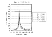
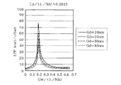
次に、図5〜図13を参照して、上記式(1)(2)を検証する。
図5〜図8は、グルーブ幅Gw、プリピット長Lp、グルーブ深さGd、波長λ及び開口数NAを様々に変化させ、それによって得られたランドプリピット検出信号SRFをどの程度高い精度で検出することができたかを実験によって求めた特性図である。
【0042】
尚、これらの図5〜図8において、ランドプリピット検出信号SLPとRF信号SRFをどの程度高い精度で検出することができたか判定するための基準として、横軸をグルーブ幅Gwに対する直径rの比、すなわち、Gw/(λ/NA)とし、縦軸をRF信号S RF のオフセットレベル(offset)に対するランドプリピット検出信号S Lp の電圧振幅(LPP level)の比(LPP level/offset)とし、更に、グルーブ深さGdとプリピット長Lpを変化させることとした。ここで、比(LPP level/offset)とは、ランドプリピット検出信号S Lp の電圧振幅(LPP level)を分子、RF信号S RF のオフセットレベル(offset)を分母として定義されるものである。
【0043】
また、オフセットレベル(offset)は、図3(a)〜(c)に示したRF信号SRFの交流成分をRF信号SRFの直流成分で規格化したパラメータ、電圧振幅(LPP level)は、ランドプリピット検出信号SLpをRF信号SRFの直流成分で規格化したパラメータである。
【0044】
より具体的には、RF信号SRFの交流成分をSRF(AC)で表すものとすると、オフセットレベル(offset)は次式(3)で、電圧振幅(LPP level)は次式(4)で、更に、比(LPP level/offset)は次式(5)でそれぞれ表される。
offset=(SRF(AC)/SRF) …(3)
LPP level=(SLP/SRF) …(4)
LPP level/offset=(SLP/SRF(AC)) …(5)
そして、図5〜図8において、グルーブGdを20nm〜35nmの範囲で5nmずつ変化させ、更に、図5は、Lp/(λ/NA)=0.128に設定し、図6は、Lp/(λ/NA)=0.2515に設定し、図7は、Lp/(λ/NA)=0.3815に設定し、図8は、Lp/(λ/NA)=0.505にそれぞれ設定して計測したときの結果を示している。
【0045】
これらの図5〜図8から明らかなように、ランドプリピット検出信号SLpとRF信号SRFをどの程度高い精度で検出できたか表す「 LPP level/offset」の値が約10のときを境にして計測結果が大きく変化し、「 LPP level/offset」が最大値になるときが、最も良い設計条件であることが確認された。
【0046】
すなわち、 LPP level/offset≒10が、ランドプリピット検出信号SLpとRF信号SRFとを高い精度で検出するための変曲点であることが確認された。このように、2つの変曲点の範囲内では、得られる特性が良いので、この範囲内の値を使うことで、良好な記録媒体が得られる。
【0047】
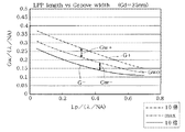
そこで、これらの図5〜図8に示す実験結果に基づいて、グルーブ深さGdをパラメータとしたときのLp/(λ/NA)とGw/(λ/NA)の関係を求めたのが、図9〜図12に示す特性図である。
【0048】
尚、図9〜図12において、1点鎖線で示す曲線Gwoは、図5〜図8中の「LPP level/offset」が最大値になる場合をプロットして示し、2点鎖線で示す曲線G+と実線で示す曲線G-は、図5〜図8中の「LPP level/offset」が約10なる場合をプロットして示したものである。更に、2点鎖線で示す曲線G+は、図5〜図8中の右側の位置で約10になる場合、実線で示す曲線G-は、図5〜図8中の左側の位置で約10になる場合である。
【0049】
よって、図9〜図12において、曲線G+と曲線G-で挟まれた範囲Gw+とGw-が、最適設計のための条件であることが分かる。尚、図9〜図12中の1点鎖線で示す曲線Gwoはほとんど変化せず、次式(6)で近似することができる。
Gw/(λ/NA)=0.2093{Lp/(λ/NA)}2
−0.4342Lp/(λ/NA)+0.332 …(6)
また、図9〜図12により、曲線G+とG-は、曲線Gwoを平行移動させたものにほぼ等しいことが分かる。したがって、その平行移動量をそれぞれの範囲Gw+とGw-として、図9〜図12の結果を、グルーブ幅GdとGw+/(λ/NA)の関係と、グルーブ深さGdとGw-/(λ/NA)の関係に転写して表すと、図13に示す結果が得られ、図13中の曲線Gw+と曲線Gw-で挟まれた範囲が最適設計のための条件となる。尚、図13中の曲線Gw+は次式(7)で、曲線Gw-は次式(8)で近似することができる。
Gw/(λ/NA)=-4.48Gd+0.2112 …(7)
Gw/(λ/NA)=-2.64Gd+0.1276 …(8)
そして、図13の曲線Gw+と曲線Gw-で挟まれた範囲を求めた結果、上記式(1)(2)が得られた。すなわち、上記式(6)が最も良い設計条件であることから、これを基準として上記式(7)と(8)を適用すると、上記式(1)(2)が最適設計条件として求められる。
【0050】
このように本実施形態の光ディスクは、上記式(1)(2)の条件に基づいて、グルーブ1のグルーブ幅Gwと、ランドプリピット3のプリピット長Lpと、グルーブ深さGdと、光スポットSPの大きさ(直径r)の形状が決められているので、グルーブ1とランドプリピット3で反射される反射光を常に最適な光量に設定することができる。すなわち、グルーブ1の情報とランドプリピット3の情報を高精度で検出することができように、グルーブ1とランドプリピット3で反射される反射光を常に最適な光量に設定することができる。そして、グルーブ1の情報とランドプリピット3の情報を高精度で検出することができるため、高密度での記録・再生を安定的に実現し得る光ディスクを提供することができる。
【0051】
また、上記式(1)(2)に基づいて、記録再生媒体に備えられている光源の射出光の波長と対物レンズの開口数を設定することにより、高密度の光ディスクを用いて安定的に記録・再生を行うための記録再生媒体を実現することができる。
【0052】
【発明の効果】
以上説明したように本発明によれば、所定開口数の対物レンズで収束された所定波長の光がグルーブに位置づけて走査される記録再生媒体において、グルーブ幅と、プリピット長と、グルーブ深さを、所定の最適条件に基づいて形成したので、グルーブからの反射光とランドプリピットからの反射光のそれぞれの光量が、グルーブの情報とランドプリピットの情報とを最適状態で検出することが可能となり、ひいては高精度且つ高密度での記録・再生を安定的に実現することができる。
【0053】
また、所定波長の光を射出する光源と、グルーブとグルーブ間のランドにランドプリピットとが形成されている記録再生媒体の上記グルーブに位置づけて、上記光源からの光を収束して走査する所定開口数の対物レンズとを備えた記録再生装置において、上記の波長と開口数を、記録再生媒体のグルーブ幅とランドプリピットのプリピット長と、グルーブとランドとの厚み方向のグルーブ深さに対して、所定の最適条件に基づいて設定したので、グルーブからの反射光とランドプリピットからの反射光のそれぞれの光量を、グルーブの情報とランドプリピットの情報とを最適状態で検出するための光量に設定することができる。この結果、高精度且つ高密度での記録・再生を安定的に実現することができる。
【図面の簡単な説明】
【図1】本実施形態の光ディスクの構造を模式的に示す図である。
【図2】本実施形態の光ディスクからランドプリピットの情報を読み出すための原理を説明するための説明図である。
【図3】未記録状態の光ディスクから読み出したランドプリピット検出信号とRF信号の波形を示す波形図である。
【図4】記録済み状態の光ディスクから読み出したランドプリピット検出信号とRF信号の波形を示す波形図である。
【図5】ランドプリピット検出信号とRF信号とが最適状態で検出されたかを判断するための説明図である。
【図6】更に、ランドプリピット検出信号とRF信号とが最適状態で検出されたかを判断するための説明図である。
【図7】更に、ランドプリピット検出信号とRF信号とが最適状態で検出されたかを判断するための説明図である。
【図8】更に、ランドプリピット検出信号とRF信号とが最適状態で検出されたかを判断するための説明図である。
【図9】更に、ランドプリピット検出信号とRF信号とが最適状態で検出されたかを判断するための説明図である。
【図10】更に、ランドプリピット検出信号とRF信号とが最適状態で検出されたかを判断するための説明図である。
【図11】更に、ランドプリピット検出信号とRF信号とが最適状態で検出されたかを判断するための説明図である。
【図12】更に、ランドプリピット検出信号とRF信号とが最適状態で検出されたかを判断するための説明図である。
【図13】更に、ランドプリピット検出信号とRF信号とが最適状態で検出されたかを判断するための説明図である。
【符号の説明】
1…グルーブ
2…ランド
3…ランドプリピット
4…透明基板
5…記録層
6…反射層
7…保護層
8…対物レンズ
9…光検出器
10〜12…加減算回路
SP…光スポット[0001]
BACKGROUND OF THE INVENTION
The present invention relates to a recording / reproducing medium such as an optical disc on which information can be written, and a recording / reproducing apparatus using the recording / reproducing medium.
[0002]
[Prior art]
Conventionally, a DVD (digital video disc or digital versatile disc) capable of recording multimedia information such as video, audio, and computer data with high density is known as this type of recording / reproducing medium.
[0003]
In addition to the read-only DVD-ROM that has been widely used for DVDs, DVD-R (recordable DVD) that can be recorded and reproduced and DVD-RW that is rewritable and recordable are known. Yes.
[0004]
In DVD-R and DVD-RW, in order to record information in the groove with high accuracy and high density, various information such as addresses are set in advance in the land between the grooves as a physical format. A method of forming pits called land pre-pits has been proposed (Japanese Patent Laid-Open No. 9-17029).
[0005]
That is, in this type of DVD-R and DVD-RW, the land pre-pit is formed adjacent to the groove. For this reason, when a light spot is positioned on the groove and scanned, the light spot is also incident on the land pre-pit. The reflected light from the land pre-pit is detected by a photodetector or the like, and the address is detected. A detection signal having various information such as can be generated.
[0006]
[Problems to be solved by the invention]
By the way, in the DVD-R and DVD-RW adopting the above method, since the land pre-pit is formed adjacent to the groove, when the light spot is scanned on the groove, the light spot is incident on the land pre-pit. When it does, it will inevitably enter the groove.
[0007]
Therefore, the reflected light includes not only the reflected light from the land pre-pit but also the reflected light from the groove, and the detection signal output from the photodetector or the like is also reflected in the reflected light from the land pre-pit. In addition to the component, the reflected light component from the groove is included.
[0008]
For this reason, the reflected light component from the groove acts as noise with respect to the reflected light component from the land prepit, and it may be difficult to detect the land prepit information from the detection signal with high accuracy. .
[0009]
On the other hand, when the information recorded in the group is read by scanning with the above light spot, the amount of reflected light from the groove is changed compared to the amount of reflected light from the land prepit. If it is small, the reflected light component from the land pre-pit acts as noise with respect to the reflected light component from the groove, and it may be difficult to detect the groove information from the above detection signal with high accuracy. .
[0010]
As described above, if the amount of reflected light reflected by the groove and the land pre-pit is not appropriate, the groove information and the land pre-pit information cannot be detected in an optimum state. It may be an impediment to density recording / reproduction.
[0011]
However, until now, it has not been said that sufficient research has been conducted on the cause and optimization of such onset.
[0012]
The present invention has been made to pose such a new problem, and has a structure that satisfies the optimum conditions among the groove, the land pre-pit, and the light spot, and has high accuracy and high density. It is an object of the present invention to provide a recording / reproducing medium capable of stably realizing recording / reproducing and a recording / reproducing apparatus using the recording / reproducing medium.
[0013]
[Means for Solving the Problems]
The invention described in
According to a second aspect of the present invention, a groove and a land formed with a predetermined track pitch and a spot light having a predetermined wavelength (λ) converged by an objective lens having a predetermined numerical aperture (NA) are scanned with the groove. Land prepits formed on the lands at predetermined intervals along the direction in which the land prepits are formed together with the grooves by the spot light irradiated in alignment with the grooves during information recording or information reproduction. In an optical disc as an information recording medium on which pits are scanned, a groove width (Gw) in a direction substantially orthogonal to the scanning direction of the groove and a prepit in each of the land prepits in the scanning direction The length (Lp) and the groove depth (Gd; unit μm) in the thickness direction between the groove and the land are Gw / (λ / NA) ≧ 0.2093 {Lp / (λ / NA)} 2 −0.4342 Lp / (λ / NA) +0.332 − (− 2.64 Gd + 0.1276) and Gw / (λ / NA) ≦ 0.2093 {Lp / (λ / NA)} 2 It is characterized by satisfying the relationship of −0.4342Lp / (λ / NA) +0.332 + (− 4.48Gd + 0.2112).
[0014]
Claim3The invention described in 1), grooves and lands formed at a predetermined track pitch,Of a given wavelength (λ)Land pre-pits formed on the land at predetermined intervals along the direction in which the groove is scanned by spot light.An optical disc which is an information recording medium in which the land pre-pits are scanned together with the groove by the spot light irradiated in alignment with the grooveOn the other hand, in a recording / reproducing apparatus for performing information recording or information reproduction,A light source that emits light of the predetermined wavelength (λ), and an objective lens having a predetermined numerical aperture (NA) that converges the light from the light source to generate the spot light, and the wavelength (λ) The numerical aperture (NA) is defined by the groove width (Gw) in the direction substantially orthogonal to the scanning direction of the groove and the prepit length (Lp) of each land prepit in the scanning direction. Gw / (λ / NA) = 0.2093 {Lp / (λ / NA)} 2 -0.4342Lp / (λ / NA) +0.332 is set,It is characterized by.
According to a fourth aspect of the present invention, grooves and lands formed at a predetermined track pitch are formed on the lands at predetermined intervals along a direction in which the grooves are scanned by spot light having a predetermined wavelength (λ). Information recording or information reproduction is performed on an optical disc that is an information recording medium having a land pre-pit and the land pre-pit is scanned together with the groove by the spot light irradiated in alignment with the groove. In the recording / reproducing apparatus, a light source that emits light of the predetermined wavelength (λ), and an objective lens having a predetermined numerical aperture (NA) that converges the light from the light source to generate the spot light, The wavelength (λ) and the numerical aperture (NA) are determined by the groove width (Gw) in the direction substantially orthogonal to the scanning direction of the groove, and the land prefixes. Gw / (λ / NA) ≧ 0.2093 {Lp / () with respect to the prepit length (Lp) in the scanning direction and the groove depth (Gd; μm) in the thickness direction between the groove and the land. λ / NA)} 2 −0.4342 Lp / (λ / NA) +0.332 − (− 2.64 Gd + 0.1276) and Gw / (λ / NA) ≦ 0.2093 {Lp / (λ / NA)} 2 It is characterized by being set to a relationship of −0.4342 Lp / (λ / NA) +0.332 + (− 4.48 Gd + 0.2112).
[0017]
DETAILED DESCRIPTION OF THE INVENTION
Hereinafter, embodiments of the present invention will be described with reference to the drawings. An embodiment of DVD-R and DVD-RW that are optical disks will be described. FIG. 1A is a perspective view schematically showing the basic structure of the DVD-R and DVD-RW of this embodiment, and FIG. 1B is the radial direction of the DVD-R and DVD-RW of this embodiment. It is sectional drawing which shows typically a longitudinal cross-section structure.
[0018]
In FIG. 1A, a
[0019]
Further, when formed along any one of the spiral track and the concentric track, the longitudinal cross section in the direction (radial direction) θr substantially orthogonal to the optical scanning direction θt, As shown in FIG. 5B, a large number of
[0020]
On both sides of each
[0021]
The
[0022]
Then, light for recording or reproduction is spot-irradiated on the
[0023]
In the optical disk having such a structure, the width (hereinafter referred to as groove width) Gw of the
[0024]
Next, the principle for performing information recording and information reproduction using this optical disc will be described with reference to FIGS.
[0025]
In FIG. 2A, light of a predetermined wavelength λ emitted from a laser diode that is a light source is collected by a collimator lens by an optical pickup device or the like, and the light emitted from the collimator lens is further shown in FIG. By irradiating the top surface of the
[0026]
Then, by rotating the present optical disk, the light spot SP is positioned in the
[0027]
Further, when the light spot SP is positioned in the
[0028]
Here, as an example, the
[0029]
That is, as schematically shown in FIGS. 2 (a) and 2 (b), the reflected light from the regions A, B, C, D divided into four equal parts of the light spot SP is converted into the
[0030]
The adder /
[0031]
Next, the optimum conditions of the groove width Gw of the
[0032]
The land pre-pit detection signal S based on the principle described with reference to FIG.LpAnd RF signal SRFIn a general recording / reproducing apparatus that generates the above, if the light spot SP is simultaneously connected to the
[0033]
Therefore, the present inventor obtained experimental results as shown in FIGS. 3A to 3C in order to confirm the cause of the problem before optimally designing the structure of the optical disk.
[0034]
FIG.(C)2 for the DVD-RW provided with the
[0035]
Further, FIG. 9A shows the case where the prepit length Lp is set to 0.3 μm and the groove width Gw is set to 0.25 μm, and FIG. 9B shows the case where Lp = 0.3 μm and Gw = 0.30 μm. In the case of setting, (c) in the figure shows a case where Lp = 0.3 μm and Gw = 0.40 μm.
[0036]
From these experimental results, if the prepit length Lp and the groove width Gw are different, the respective signals S at the time t when the light spot SP is irradiated onto the
[0037]
Further, each of FIGS. 4A to 4C shows a land pre-pit detection signal S read from an optical disk in which information is written in the groove 1.LpAnd RF signal SRFIs shown in correspondence with FIGS. 3A to 3C. As apparent from the experimental results of FIGS. 4A to 4C, when the prepit length Lp and the groove width Gw are different, the light spot SP is irradiated to the
[0038]
Focusing on the fact that the cause of this variation is based on the correlation between the size of the
[0039]
First, the conclusion of the optimum condition will be explained. The ratio r (λ / NA) of the numerical aperture NA of the
[0040]
Gw / (λ / NA) ≧ 0.2093 {Lp / (λ / NA)}2
−0.4342Lp / (λ / NA) +0.332 − (− 2.64Gd + 0.1276) (1)
Gw / (λ / NA) ≦ 0.2093 {Lp / (λ / NA)}2
-0.4342Lp / (λ / NA) +0.332 + (-4.48Gd + 0.2112) (2)
When the optical disc is designed according to the conditions of the above formulas (1) and (2), when applied to a general recording / reproducing apparatus as shown in FIG. The land pre-pit detection signal S is detected from the reflected light even when the light is simultaneously irradiated.LpAnd RF signal SRFCan be detected with high accuracy.
[0041]
Next, the above formulas (1) and (2) will be verified with reference to FIGS.
5 to 8 show the land prepit detection signal S obtained by changing the groove width Gw, the prepit length Lp, the groove depth Gd, the wavelength λ, and the numerical aperture NA in various ways.RFIt is the characteristic figure which calculated | required by the experiment how much accuracy was able to be detected.
[0042]
5 to 8, the land pre-pit detection signal SLPAnd RF signal SRFIs a ratio for the diameter r to the groove width Gw, that is, Gw / (λ / NA), and the vertical axisRF signal S RF Offset level (offset)AgainstLand pre-pit detection signal S Lp Voltage amplitude (LPP level) ratio (LPP level / offset)Further, the groove depth Gd and the prepit length Lp are changed.Here, the ratio (LPP level / offset) is the land pre-pit detection signal S. Lp Voltage amplitude (LPP level) of numerator, RF signal S RF The offset level (offset) is defined as the denominator.
[0043]
The offset level (offset) is the RF signal S shown in FIGS.RFRF signal SRFThe parameter and voltage amplitude (LPP level) normalized by the DC component of the land pre-pit detection signal SLpRF signal SRFThis parameter is normalized by the direct current component.
[0044]
More specifically, the RF signal SRFAC component of SRF (AC), The offset level (offset) is expressed by the following equation (3), the voltage amplitude (LPP level) is expressed by the following equation (4), and the ratio (LPP level / offset) is expressed by the following equation (5). expressed.
offset = (SRF (AC)/ SRF(3)
LPP level = (SLP/ SRF) …(Four)
LPP level / offset = (SLP/ SRF (AC)) …(Five)
And figure5In FIG. 8, the groove Gd is changed by 5 nm in the range of 20 nm to 35 nm, and further,5Is set to Lp / (λ / NA) = 0.128.6Is set to Lp / (λ / NA) = 0.2515,7Is set to Lp / (λ / NA) = 0.3815,8These show the results when measurement was performed with Lp / (λ / NA) = 0.505 set.
[0045]
As is apparent from FIGS. 5 to 8, the land pre-pit detection signal SLpAnd RF signal SRFWhen the value of “LPP level / offset” that expresses how accurately the value of “LPP level / offset” is about 10, the measurement result changes greatly, and the time when “LPP level / offset” becomes the maximum value is the best. The design conditions were confirmed.
[0046]
That is, LPP level / offset≈10 is the land pre-pit detection signal SLpAnd RF signal SRFIt was confirmed that this is an inflection point for detecting the above with high accuracy. Thus, since the obtained characteristics are good within the range of the two inflection points, a good recording medium can be obtained by using a value within this range.
[0047]
Therefore, the relationship between Lp / (λ / NA) and Gw / (λ / NA) when the groove depth Gd is used as a parameter based on the experimental results shown in FIGS. It is a characteristic view shown in FIGS.
[0048]
9 to 12, a curve Gwo indicated by a one-dot chain line is plotted by plotting a case where “LPP level / offset” in FIGS. 5 to 8 is the maximum value, and a curve G indicated by a two-dot chain line. A curve G− indicated by + and a solid line is a plot of the case where “LPP level / offset” in FIGS. Furthermore, when the curve G + indicated by the two-dot chain line is approximately 10 at the right position in FIGS. 5 to 8, the curve G− indicated by the solid line is approximately 10 at the left position in FIGS. This is the case.
[0049]
Therefore, in FIGS. 9 to 12, it can be seen that the range Gw + and Gw− sandwiched between the curve G + and the curve G− are the conditions for the optimum design. In addition, the curve Gwo shown with the dashed-dotted line in FIGS. 9-12 hardly changes, and can be approximated by following Formula (6).
Gw / (λ / NA) = 0.2093 {Lp / (λ / NA)}2
-0.4342Lp / (λ / NA) +0.332 (6)
9 to 12, it can be seen that the curves G + and G- are substantially equal to the curve Gwo translated. Accordingly, assuming that the parallel movement amounts are the respective ranges Gw + and Gw−, the results of FIGS. 9 to 12 are obtained from the relationship between the groove width Gd and Gw + / (λ / NA) and the groove depths Gd and Gw − / (λ / NA), the result shown in FIG. 13 is obtained, and the range between the curve Gw + and the curve Gw− in FIG. 13 is a condition for optimum design. The curve Gw + in FIG. 13 can be approximated by the following equation (7), and the curve Gw− can be approximated by the following equation (8).
Gw / (λ / NA) = − 4.48Gd + 0.2112 (7)
Gw / (λ / NA) = − 2.64Gd + 0.1276 (8)
And as a result of calculating | requiring the range pinched | interposed by the curve Gw + and the curve Gw- of FIG. 13, the said Formula (1) (2) was obtained. That is, since the above formula (6) is the best design condition, when the above formulas (7) and (8) are applied based on this, the above formulas (1) and (2) are obtained as the optimum design conditions.
[0050]
As described above, the optical disc of the present embodiment is based on the conditions of the above formulas (1) and (2), the groove width Gw of the
[0051]
Further, by setting the wavelength of the light emitted from the light source provided in the recording / reproducing medium and the numerical aperture of the objective lens based on the above formulas (1) and (2), the high-density optical disc can be used stably. A recording / reproducing medium for recording / reproducing can be realized.
[0052]
【The invention's effect】
As described above, according to the present invention, in a recording / reproducing medium in which light having a predetermined wavelength converged by an objective lens having a predetermined numerical aperture is scanned while being positioned in a groove, the groove width, the prepit length, and the groove depth are set. Since it is formed based on a predetermined optimum condition, the amount of reflected light from the groove and reflected light from the land pre-pit can detect the groove information and the land pre-pit information in an optimum state. As a result, recording / reproduction with high accuracy and high density can be stably realized.
[0053]
Further, a light source that emits light of a predetermined wavelength, and a groove that is positioned on the groove of a recording / reproducing medium in which land prepits are formed in the land between the grooves, the light from the light source is converged and scanned. In a recording / reproducing apparatus equipped with an objective lens having a numerical aperture, the above-mentioned wavelength and numerical aperture are determined with respect to the groove width of the recording / reproducing medium, the prepit length of the land prepit, and the groove depth in the thickness direction of the groove and land. In order to detect the light quantity of the reflected light from the groove and the reflected light from the land pre-pit in the optimum state, the information on the groove and the information on the land pre-pit are set. The light intensity can be set. As a result, recording / reproduction with high accuracy and high density can be realized stably.
[Brief description of the drawings]
FIG. 1 is a diagram schematically showing the structure of an optical disc according to an embodiment.
FIG. 2 is an explanatory diagram for explaining the principle for reading information of land prepits from the optical disc of the present embodiment;
FIG. 3 is a waveform diagram showing waveforms of a land pre-pit detection signal and an RF signal read from an unrecorded optical disc.
FIG. 4 is a waveform diagram showing waveforms of a land pre-pit detection signal and an RF signal read from an optical disc in a recorded state.
FIG. 5 is an explanatory diagram for determining whether a land pre-pit detection signal and an RF signal are detected in an optimum state.
FIG. 6 is an explanatory diagram for determining whether a land pre-pit detection signal and an RF signal are detected in an optimum state.
FIG. 7 is an explanatory diagram for determining whether a land pre-pit detection signal and an RF signal are detected in an optimum state;
FIG. 8 is an explanatory diagram for determining whether a land pre-pit detection signal and an RF signal are detected in an optimum state.
FIG. 9 is an explanatory diagram for determining whether a land pre-pit detection signal and an RF signal are detected in an optimum state.
FIG. 10 is an explanatory diagram for determining whether a land pre-pit detection signal and an RF signal are detected in an optimum state.
FIG. 11 is an explanatory diagram for determining whether a land pre-pit detection signal and an RF signal are detected in an optimum state.
FIG. 12 is an explanatory diagram for determining whether a land pre-pit detection signal and an RF signal are detected in an optimum state.
FIG. 13 is an explanatory diagram for determining whether a land pre-pit detection signal and an RF signal are detected in an optimum state;
[Explanation of symbols]
1 ... Groove
2 ... Land
3 ... Land pre-pit
4 ... Transparent substrate
5. Recording layer
6 ... Reflective layer
7 ... Protective layer
8 ... Objective lens
9 ... Photodetector
10-12 ... Addition / subtraction circuit
SP ... Light spot
Claims (6)
前記グルーブの前記走査される方向に対して略直交する方向におけるグルーブ幅(Gw)と、前記各々のランドプリピットの前記走査される方向におけるプリピット長(Lp)が、
Gw/(λ/NA)=0.2093{Lp/(λ/NA)} 2 −0.4342Lp/(λ/NA)+0.332
の関係を満たしていること、
を特徴とする光ディスク。The grooves and lands formed at a predetermined track pitch, and the spot light having a predetermined wavelength (λ) converged by an objective lens having a predetermined numerical aperture (NA) at a predetermined interval along the scanning direction of the groove. An information recording medium having a land pre-pit formed on a land, and wherein the land pre-pit is scanned together with the groove by the spot light irradiated in alignment with the groove when recording or reproducing information In an optical disc,
A groove width (Gw) in a direction substantially orthogonal to the scanning direction of the groove, and a prepit length (Lp) in the scanning direction of each land prepit,
Gw / (λ / NA) = 0.2093 {Lp / (λ / NA)} 2 −0.4342 Lp / (λ / NA) +0.332
Satisfying the relationship,
An optical disc characterized by
前記グルーブの前記走査される方向に対して略直交する方向におけるグルーブ幅(Gw)と、前記各々のランドプリピットの前記走査される方向におけるプリピット長(Lp)と、前記グルーブと前記ランドとの厚み方向のグルーブ深さ(Gd;単位μm)が、
Gw/(λ/NA)≧0.2093{Lp/(λ/NA)}2 −0.4342Lp/(λ/NA)+0.332−(−2.64Gd+0.1276)
且つ、
Gw/(λ/NA)≦0.2093{Lp/(λ/NA)}2 −0.4342Lp/(λ/NA)+0.332+(−4.48Gd+0.2112)
の関係を満たしていること、
を特徴とする光ディスク。 The grooves and lands formed at a predetermined track pitch, and the spot light having a predetermined wavelength (λ) converged by an objective lens having a predetermined numerical aperture (NA) at a predetermined interval along the scanning direction of the groove. An information recording medium having a land pre-pit formed on a land, and wherein the land pre-pit is scanned together with the groove by the spot light irradiated in alignment with the groove when recording or reproducing information In an optical disc,
A groove width (Gw) in a direction substantially perpendicular to the direction in which the scanning of the groove, and the pre-pit length (L p) in the direction in which the scanning of each of the land prepits, and the said groove land The groove depth in the thickness direction ( Gd ; unit μm) is
Gw / (λ / NA) ≧ 0.2093 {Lp / (λ / NA)} 2 −0.4342 Lp / (λ / NA) +0.332 − (− 2.64 Gd + 0.1276)
and,
Gw / (λ / NA) ≦ 0.2093 {Lp / (λ / NA)} 2 −0.4342Lp / (λ / NA) +0.332 + (− 4.48Gd + 0.2112)
Rukoto not meet the relationship,
An optical disc characterized by
前記所定波長(λ)の光を射出する光源と、
前記光源からの光を収束して前記スポット光を生じさせる、所定開口数(NA)の対物レンズとを有し、
前記波長(λ)と開口数(NA)は、
前記グルーブの前記走査の方向に対して略直交する方向におけるグルーブ幅(Gw)と、前記各々のランドプリピットの前記走査の方向におけるプリピット長(Lp)に対して、
Gw/(λ/NA)=0.2093{Lp/(λ/NA)} 2 −0.4342Lp/(λ/NA)+0.332
の関係に設定されていること、
を特徴とする記録再生装置。 Possess the groove and land formed at a predetermined track pitch, and a land pre-pit formed on the land at a predetermined distance along the direction to be scanned in the groove by spot light of a predetermined wavelength (lambda), the In a recording / reproducing apparatus for performing information recording or information reproduction on an optical disc , which is an information recording medium in which the land pre-pits are scanned together with the groove by the spot light irradiated in alignment with the groove ,
A light source that emits light of the predetermined wavelength (λ);
An objective lens having a predetermined numerical aperture (NA) that converges light from the light source to generate the spot light;
The wavelength (λ) and numerical aperture (NA) are:
The groove width (Gw) in a direction substantially orthogonal to the scanning direction of the groove and the prepit length (Lp) in the scanning direction of each land prepit,
Gw / (λ / NA) = 0.2093 {Lp / (λ / NA)} 2 −0.4342 Lp / (λ / NA) +0.332
That is set in the relationship
A recording / reproducing apparatus.
前記所定波長(λ)の光を射出する光源と、
前記光源からの光を収束して前記スポット光を生じさせる、所定開口数(NA)の対物レンズとを有し、
前記波長(λ)と開口数(NA)は、
前記グルーブの前記走査の方向に対して略直交する方向におけるグルーブ幅(Gw)と、前記各々のランドプリピットの前記走査の方向におけるプリピット長(Lp)と、前記グルーブと前記ランドとの厚み方向のグルーブ深さ(Gd;単位μm)に対して、
Gw/(λ/NA)≧0.2093{Lp/(λ/NA)}2 −0.4342Lp/(λ/NA)+0.332−(−2.64Gd+0.1276)
且つ、
Gw/(λ/NA)≦0.2093{Lp/(λ/NA)}2 −0.4342Lp/(λ/NA)+0.332+(−4.48Gd+0.2112)
の関係に設定されていること、
を特徴とする記録再生装置。 Grooves and lands formed at a predetermined track pitch, and land prepits formed on the lands at predetermined intervals along a direction in which the groove is scanned by spot light having a predetermined wavelength (λ), In a recording / reproducing apparatus for performing information recording or information reproduction on an optical disc, which is an information recording medium in which the land pre-pits are scanned together with the groove by the spot light irradiated in alignment with the groove,
A light source for emitting light of predetermined wavelength (lambda),
An objective lens having a predetermined numerical aperture ( NA ) that converges light from the light source to generate the spot light ;
The wavelength ( λ ) and the numerical aperture ( NA ) are
Groove width ( Gw ) in a direction substantially orthogonal to the scanning direction of the groove, prepit length ( Lp ) in the scanning direction of each land prepit, and thickness direction of the groove and the land For the groove depth ( Gd ; unit μm)
Gw / (λ / NA) ≧ 0.2093 {Lp / (λ / NA)} 2 −0.4342 Lp / (λ / NA) +0.332 − (− 2.64 Gd + 0.1276)
and,
Gw / (λ / NA) ≦ 0.2093 {Lp / (λ / NA)} 2 −0.4342Lp / (λ / NA) +0.332 + (− 4.48Gd + 0.2112)
That is set in the relationship
A recording / reproducing apparatus.
Priority Applications (13)
| Application Number | Priority Date | Filing Date | Title |
|---|---|---|---|
| JP30196598A JP4372867B2 (en) | 1998-10-23 | 1998-10-23 | Optical disc and recording / reproducing apparatus |
| US09/419,908 US6181672B1 (en) | 1998-10-23 | 1999-10-18 | Recording medium and a recording system for the recording medium |
| DE69940677T DE69940677D1 (en) | 1998-10-23 | 1999-10-21 | Recording medium and recording system for this purpose |
| DE69920368T DE69920368T2 (en) | 1998-10-23 | 1999-10-21 | Recording medium and recording system for this purpose |
| EP99121065A EP0996118B1 (en) | 1998-10-23 | 1999-10-21 | Recording medium and a recording system for the recording medium |
| EP04022466A EP1486958B1 (en) | 1998-10-23 | 1999-10-21 | Recording medium and recording system for the recording medium |
| CNB2005100775896A CN100342438C (en) | 1998-10-23 | 1999-10-25 | Recording medium and a recording system for the recording medium |
| CNB2004100797867A CN100568357C (en) | 1998-10-23 | 1999-10-25 | Recording medium reaches the system of recorded information on recording medium |
| CNB991236238A CN1175405C (en) | 1998-10-23 | 1999-10-25 | Record regeneration medium and record regenerator using record regeneration medium |
| US09/758,393 US6493313B2 (en) | 1998-10-23 | 2001-01-12 | Recording medium having grooves and prepits and a recording system for the recording medium |
| US10/274,199 US6952393B2 (en) | 1998-10-23 | 2002-10-21 | Recording medium and a recording system for the recording medium |
| HK05104979.2A HK1073527A1 (en) | 1998-10-23 | 2005-06-15 | Recording medium and recording system for the recording medium |
| HK06101709A HK1081718A1 (en) | 1998-10-23 | 2006-02-09 | Recording medium and a recording system for the recording medium |
Applications Claiming Priority (1)
| Application Number | Priority Date | Filing Date | Title |
|---|---|---|---|
| JP30196598A JP4372867B2 (en) | 1998-10-23 | 1998-10-23 | Optical disc and recording / reproducing apparatus |
Publications (3)
| Publication Number | Publication Date |
|---|---|
| JP2000132868A JP2000132868A (en) | 2000-05-12 |
| JP2000132868A5 JP2000132868A5 (en) | 2008-05-08 |
| JP4372867B2 true JP4372867B2 (en) | 2009-11-25 |
Family
ID=17903267
Family Applications (1)
| Application Number | Title | Priority Date | Filing Date |
|---|---|---|---|
| JP30196598A Expired - Fee Related JP4372867B2 (en) | 1998-10-23 | 1998-10-23 | Optical disc and recording / reproducing apparatus |
Country Status (6)
| Country | Link |
|---|---|
| US (3) | US6181672B1 (en) |
| EP (2) | EP1486958B1 (en) |
| JP (1) | JP4372867B2 (en) |
| CN (3) | CN100568357C (en) |
| DE (2) | DE69920368T2 (en) |
| HK (2) | HK1073527A1 (en) |
Families Citing this family (25)
| Publication number | Priority date | Publication date | Assignee | Title |
|---|---|---|---|---|
| JP4372867B2 (en) * | 1998-10-23 | 2009-11-25 | パイオニア株式会社 | Optical disc and recording / reproducing apparatus |
| EP1043714B1 (en) * | 1999-04-08 | 2007-02-21 | Pioneer Corporation | Optical recording medium |
| US6535477B1 (en) * | 1999-06-28 | 2003-03-18 | Pioneer Corporation | Optical recording medium having groove and land tracks, and method of manufacturing the same |
| KR20010097980A (en) * | 2000-04-27 | 2001-11-08 | 이진섭 | Constant output channel power gain flattened optical amplifier |
| JP4136280B2 (en) * | 2000-07-04 | 2008-08-20 | パイオニア株式会社 | Optical recording medium, manufacturing method and manufacturing apparatus |
| JP2002237102A (en) | 2000-07-07 | 2002-08-23 | Tdk Corp | Optical recording medium and method of manufacturing for the same |
| JP4226204B2 (en) | 2000-09-14 | 2009-02-18 | パイオニア株式会社 | Optical recording medium, manufacturing apparatus and manufacturing method thereof |
| JP2002140840A (en) * | 2000-11-01 | 2002-05-17 | Pioneer Electronic Corp | Optical disk and original disk manufacturing device |
| TW577072B (en) * | 2001-07-12 | 2004-02-21 | Tdk Corp | Optical recording disc |
| US7525890B2 (en) * | 2001-09-29 | 2009-04-28 | Samsung Electronics Co., Ltd. | Method of and apparatus for recording data on optical recording medium |
| WO2004025631A1 (en) * | 2002-08-26 | 2004-03-25 | Taiyo Yuden Co., Ltd. | Optical information recording medium |
| JP4598355B2 (en) * | 2002-10-10 | 2010-12-15 | ソニー株式会社 | Disk drive device and pre-pit detection method |
| JP2004158068A (en) * | 2002-11-05 | 2004-06-03 | Pioneer Electronic Corp | Information recording medium |
| US7869171B2 (en) | 2003-12-02 | 2011-01-11 | Pass & Seymour, Inc. | Protective electrical wiring device with a center nightlight |
| DE602004014217D1 (en) * | 2003-06-10 | 2008-07-17 | Thomson Licensing | Procedure for the recovery of land pre-well |
| EP1486954A1 (en) * | 2003-06-10 | 2004-12-15 | Deutsche Thomson-Brandt Gmbh | Method for land pre-pit recovery |
| EP1494216B1 (en) * | 2003-06-10 | 2008-06-04 | Thomson Licensing | Method for land pre-pit recovery |
| EP1763873A1 (en) * | 2004-06-22 | 2007-03-21 | Koninklijke Philips Electronics N.V. | Recording system having improved prepit detection |
| KR100594725B1 (en) * | 2004-09-08 | 2006-06-30 | 삼성전자주식회사 | Optical data recording device for searching recording area by controlling tracking level, method thereof |
| JP4621550B2 (en) * | 2005-06-24 | 2011-01-26 | 東芝マイクロエレクトロニクス株式会社 | Error correction device for optical disk device |
| US7613983B2 (en) | 2005-06-24 | 2009-11-03 | Kabushiki Kaisha Toshiba | Error correction device of optical disk unit |
| US7929405B2 (en) | 2006-05-30 | 2011-04-19 | Pioneer Corporation | Recordable type information recording medium, information recording apparatus, and information recording method |
| JP4600434B2 (en) * | 2007-06-11 | 2010-12-15 | 日本ビクター株式会社 | Optical information recording medium |
| JP4609781B2 (en) * | 2008-04-30 | 2011-01-12 | 日本ビクター株式会社 | Optical information recording medium |
| US8568152B1 (en) | 2012-04-19 | 2013-10-29 | Pass & Seymour, Inc. | Shutter assembly for electrical devices |
Family Cites Families (16)
| Publication number | Priority date | Publication date | Assignee | Title |
|---|---|---|---|---|
| JP2820808B2 (en) * | 1991-03-29 | 1998-11-05 | コニカ株式会社 | Focus control mechanism of optical disk device |
| JP3133509B2 (en) * | 1992-09-29 | 2001-02-13 | パイオニア株式会社 | Optical disk and optical disk drive |
| JPH06333239A (en) * | 1993-05-20 | 1994-12-02 | Pioneer Electron Corp | Optical recording medium and information recorder |
| US5959963A (en) * | 1994-01-19 | 1999-09-28 | Kabushiki Kaisha Toshiba | Optical disk and optical disk apparatus |
| JPH07240040A (en) * | 1994-02-25 | 1995-09-12 | Pioneer Electron Corp | Optical disk |
| JP2788022B2 (en) * | 1995-02-14 | 1998-08-20 | 株式会社日立製作所 | Optical recording medium |
| JPH0917029A (en) * | 1995-06-26 | 1997-01-17 | Pioneer Electron Corp | Optical disk and its reader and production of optical disk |
| JPH0981965A (en) * | 1995-09-18 | 1997-03-28 | Hitachi Maxell Ltd | Optical recording medium and tracking method |
| JP3703569B2 (en) * | 1996-04-02 | 2005-10-05 | ソニー株式会社 | Optical recording medium, recording / reproducing method thereof, and recording / reproducing apparatus |
| JP3769829B2 (en) * | 1996-08-29 | 2006-04-26 | ソニー株式会社 | Playback apparatus and playback method |
| JP3831063B2 (en) * | 1997-04-25 | 2006-10-11 | パイオニア株式会社 | Optical disc discrimination device |
| JP3685922B2 (en) * | 1997-11-05 | 2005-08-24 | Tdk株式会社 | Optical recording medium and recording method therefor |
| DE69834708T2 (en) * | 1997-12-26 | 2007-04-26 | Kabushiki Kaisha Toshiba, Kawasaki | Optical disc and optical disc device |
| JP3732650B2 (en) * | 1998-03-26 | 2006-01-05 | パイオニア株式会社 | Pre-pit detection device |
| US6104682A (en) * | 1998-07-23 | 2000-08-15 | Matsushita Electric Industrial Co., Ltd. | Disk apparatus having a data reproducing system using a digital PLL |
| JP4372867B2 (en) * | 1998-10-23 | 2009-11-25 | パイオニア株式会社 | Optical disc and recording / reproducing apparatus |
-
1998
- 1998-10-23 JP JP30196598A patent/JP4372867B2/en not_active Expired - Fee Related
-
1999
- 1999-10-18 US US09/419,908 patent/US6181672B1/en not_active Expired - Lifetime
- 1999-10-21 DE DE69920368T patent/DE69920368T2/en not_active Expired - Lifetime
- 1999-10-21 EP EP04022466A patent/EP1486958B1/en not_active Expired - Lifetime
- 1999-10-21 EP EP99121065A patent/EP0996118B1/en not_active Expired - Lifetime
- 1999-10-21 DE DE69940677T patent/DE69940677D1/en not_active Expired - Lifetime
- 1999-10-25 CN CNB2004100797867A patent/CN100568357C/en not_active Expired - Fee Related
- 1999-10-25 CN CNB2005100775896A patent/CN100342438C/en not_active Expired - Fee Related
- 1999-10-25 CN CNB991236238A patent/CN1175405C/en not_active Expired - Fee Related
-
2001
- 2001-01-12 US US09/758,393 patent/US6493313B2/en not_active Expired - Fee Related
-
2002
- 2002-10-21 US US10/274,199 patent/US6952393B2/en not_active Expired - Lifetime
-
2005
- 2005-06-15 HK HK05104979.2A patent/HK1073527A1/en not_active IP Right Cessation
-
2006
- 2006-02-09 HK HK06101709A patent/HK1081718A1/en not_active IP Right Cessation
Also Published As
| Publication number | Publication date |
|---|---|
| DE69920368D1 (en) | 2004-10-28 |
| CN1601629A (en) | 2005-03-30 |
| CN100568357C (en) | 2009-12-09 |
| EP1486958A3 (en) | 2005-03-30 |
| EP1486958B1 (en) | 2009-04-01 |
| DE69940677D1 (en) | 2009-05-14 |
| US20010002899A1 (en) | 2001-06-07 |
| CN100342438C (en) | 2007-10-10 |
| US6493313B2 (en) | 2002-12-10 |
| CN1722265A (en) | 2006-01-18 |
| EP0996118B1 (en) | 2004-09-22 |
| DE69920368T2 (en) | 2006-02-23 |
| EP1486958A2 (en) | 2004-12-15 |
| CN1175405C (en) | 2004-11-10 |
| US6181672B1 (en) | 2001-01-30 |
| US20030053406A1 (en) | 2003-03-20 |
| CN1252595A (en) | 2000-05-10 |
| JP2000132868A (en) | 2000-05-12 |
| EP0996118A3 (en) | 2001-07-25 |
| HK1073527A1 (en) | 2005-10-07 |
| EP0996118A2 (en) | 2000-04-26 |
| HK1081718A1 (en) | 2006-05-19 |
| US6952393B2 (en) | 2005-10-04 |
Similar Documents
| Publication | Publication Date | Title |
|---|---|---|
| JP4372867B2 (en) | Optical disc and recording / reproducing apparatus | |
| US6018510A (en) | Phase change recording medium for allowing a tracking servo control based on a differential phase detection tracking method | |
| JP2006351197A (en) | Data reproducing device for optical information storage medium | |
| JP3560410B2 (en) | Optical disk device and optical disk | |
| EP1202255A2 (en) | Multi-layer information recording medium and recording apparatus for the same | |
| JP3374086B2 (en) | Magneto-optical recording medium | |
| JP2006073189A (en) | Method and apparatus for detecting disk area | |
| JP2002288855A (en) | Optical disk device | |
| JP5623948B2 (en) | Recommended recording condition determination method and recording adjustment method | |
| WO2004081928A1 (en) | Optical disk | |
| JP2636822B2 (en) | Substrate for optical recording media | |
| KR100739806B1 (en) | Apparatus for reproducing data from optical information storage medium | |
| JP4382781B2 (en) | Optical recording medium | |
| JP2002260239A (en) | Optical disk and optical original disk exposing device | |
| KR100754229B1 (en) | Apparatus for reproducing data from optical information storage medium | |
| KR100765800B1 (en) | Optical information storage medium and method for reproducing data from the same | |
| JPH1186310A (en) | Optical disk device | |
| JPH1173686A (en) | Optical storage medium | |
| JP2005158257A (en) | Information reproducing and recording method | |
| JPH0831015A (en) | Optical information recording medium and optical information recording and reproducing device | |
| US20040196746A1 (en) | Information recording medium, information recording/reproducing method, and information recording/reproducing device | |
| JPH05298705A (en) | Optical recorder/reproducer | |
| JPH051534B2 (en) | ||
| JPH0570209B2 (en) | ||
| JP2000353342A (en) | Optical recording medium |
Legal Events
| Date | Code | Title | Description |
|---|---|---|---|
| A621 | Written request for application examination |
Free format text: JAPANESE INTERMEDIATE CODE: A621 Effective date: 20051013 |
|
| A977 | Report on retrieval |
Free format text: JAPANESE INTERMEDIATE CODE: A971007 Effective date: 20071210 |
|
| A521 | Written amendment |
Free format text: JAPANESE INTERMEDIATE CODE: A523 Effective date: 20080326 |
|
| A01 | Written decision to grant a patent or to grant a registration (utility model) |
Free format text: JAPANESE INTERMEDIATE CODE: A01 Effective date: 20080401 |
|
| AA91 | Notification of revocation by ex officio |
Free format text: JAPANESE INTERMEDIATE CODE: A971091 Effective date: 20080603 |
|
| A131 | Notification of reasons for refusal |
Free format text: JAPANESE INTERMEDIATE CODE: A131 Effective date: 20080711 |
|
| A521 | Written amendment |
Free format text: JAPANESE INTERMEDIATE CODE: A523 Effective date: 20080909 |
|
| A521 | Written amendment |
Free format text: JAPANESE INTERMEDIATE CODE: A821 Effective date: 20080909 |
|
| A131 | Notification of reasons for refusal |
Free format text: JAPANESE INTERMEDIATE CODE: A131 Effective date: 20090417 |
|
| A521 | Written amendment |
Free format text: JAPANESE INTERMEDIATE CODE: A523 Effective date: 20090616 |
|
| TRDD | Decision of grant or rejection written | ||
| A01 | Written decision to grant a patent or to grant a registration (utility model) |
Free format text: JAPANESE INTERMEDIATE CODE: A01 Effective date: 20090818 |
|
| A01 | Written decision to grant a patent or to grant a registration (utility model) |
Free format text: JAPANESE INTERMEDIATE CODE: A01 |
|
| A61 | First payment of annual fees (during grant procedure) |
Free format text: JAPANESE INTERMEDIATE CODE: A61 Effective date: 20090903 |
|
| FPAY | Renewal fee payment (event date is renewal date of database) |
Free format text: PAYMENT UNTIL: 20120911 Year of fee payment: 3 |
|
| R150 | Certificate of patent or registration of utility model |
Free format text: JAPANESE INTERMEDIATE CODE: R150 |
|
| FPAY | Renewal fee payment (event date is renewal date of database) |
Free format text: PAYMENT UNTIL: 20120911 Year of fee payment: 3 |
|
| FPAY | Renewal fee payment (event date is renewal date of database) |
Free format text: PAYMENT UNTIL: 20130911 Year of fee payment: 4 |
|
| LAPS | Cancellation because of no payment of annual fees |