Technical Field
The present invention relates to an acoustic coding
apparatus and acoustic coding method which compresses
and encodes an acoustic signal such as a music signal
or speech signal with a high degree of efficiency, and
more particularly, to an acoustic coding apparatus and
acoustic coding method which carries out scalable coding
capable of even decoding music and speech from part of
a coded code.
Background Art
An acoustic coding technology which compresses a
music signal or speech signal at a lowbit rate is important
for effective utilization of a transmission path capacity
of radio wave, etc., in a mobile communication and a
recording medium. As speech coding methods for coding
a speech signal, there are methods like G726, G729 which
are standardized by the ITU (International
Telecommunication Union). These methods can perform
coding on a narrowband signal (300 Hz to 3.4 kHz) at a
bit rate of 8 kbit/s to 32 kbit/s with high quality.
Furthermore, there are standard methods for coding
a wideband signal (50 Hz to 7 kHz) like G722, G722.1 of
the ITU and AMR-WB of the 3GPP (The 3rd Generation
Partnership Project). These methods can perform coding
on a wideband speech signal at a bit rate of 6.6 kbit/s
to 64 kbit/s with high quality.
A method for effectively performing coding on a
speech signal at a low bit rate with a high degree of
efficiency is CELP (Code Excited Linear Prediction).
Based on an engineering simulating model of a human speech
generation model, the CELP is a method of causing an
excitation signal expressed by a random number or pulse
string to pass through a pitch filter corresponding to
the intensity of periodicity and a synthesis filter
corresponding to a vocal tract characteristic and
determining coding parameters so that the square error
between the output signal and input signal becomes a
minimum under weighting of a perceptual characteristic.
(For example, see "Code-Excited Linear Prediction (CELP) :
high quality speech at very low bit rates", Proc. ICASSP
85, pp.937-940, 1985.)
Many recent standard speech coding methods are based
on the CELP. For example, G729 can perform coding on a
narrowband signal at a bit rate of 8 kbit/s and AMR-WB
can perform coding on a wideband signal at a bit rate
of 6.6 kbit/s to 23.85 kbit/s.
On the other hand, in the case of audio coding where
a music signal is encoded, transform coding is generally
used which transforms a music signal to a frequency domain
and encodes the transformed coefficients using a
perceptual psychological model such as a MPEG-1 layer
3 coding and AAC coding standardized by MPEG (Moving
Picture Expert Group). These methods are known to hardly
produce deterioration at a bit rate of 64 kbit/s to 96
kbit/s per channel on a signal having a sampling rate
of 44.1 kHz.
However, when a signal which consists predominantly
of a speech signal with music and environmental sound
superimposed in the background is encoded, applying a
speech coding involves a problem that not only the signal
in the background but also the speech signal deteriorates
due to the influence of music and environmental sound
in the background, degrading the overall quality. This
is a problem caused by the fact that the speech coding
is based on a method specialized for the speech model
of the CELP. Furthermore, there is another problem that
the signal band to which the speech coding is applicable
is up to 7 kHz at most and signals having higher frequencies
cannot be covered for structural reasons.
On the other hand, music coding (audio coding)
methods allow high quality coding on music, and can thereby
obtain sufficient quality for the aforementioned speech
signal including music and environmental sound in the
background, too. Furthermore, audio coding is
applicable to a frequency band of target signals having
a sampling rate of up to approximately 22 kHz, which is
equivalent to CD quality.
On the other hand, to realize high quality coding,
it is necessary to use signals at a high bit rate and
the problem is that if the bit rate is mitigated to as
low as approximately 32 kbit/s, the quality of the decoded
signal degrades drastically. This results in a problem
that the method cannot be used for a communication network
having a low transmission bit rate.
In order to avoid the above described problems, it
is possible to adopt scalable coding combining these
technologies which performs coding on an input signal
in a base layer using CELP first and then calculates a
residual signal obtained by subtracting the decoded
signal from the input signal and carries out transform
coding on this signal in an enhancement layer.
According to this method, the base layer uses CELP
and can thereby perform coding on a speech signal with
high quality and the enhancement layer can efficiently
perform coding on music and environmental sound in the
background which cannot be expressed by the base layer
and signals with a higher frequency component than the
frequency band covered by the base layer. Furthermore,
according to this configuration, it is possible to
suppress the bit rate to a low level. In addition, this
configuration allows an acoustic signal to be decoded
from only part of a coded code, that is, a coded code
of the base layer and such a scalable function is effective
in realizing multicasting to a plurality of networks
having different transmission bit rates.
However, such scalable coding has a problem that
delays in the enhancement layer increase. This problem
will be explained using FIG.1 and FIG.2. FIG.1
illustrates an example of frames of a base layer (base
frames) and frames of an enhancement layer (enhancement
frames) in conventional speech coding. FIG.2
illustrates an example of frames of a base layer (base
frames) and frames of an enhancement layer (enhancement
frames) in conventional speech decoding.
In the conventional speech coding, the base frames
and enhancement frames are constructed of frames having
an identical time length. In FIG.1, an input signal input
from time T(n-1) to T(n) becomes an nth base frame and
is encoded in the base layer. And a residual signal from
time T (n-1) to T (n) is also coded in the enhancement layer.
Here, when an MDCT (modified discrete cosine
transform) is used in the enhancement layer, it is
necessary to make two successive MDCT analysis frames
overlap with each other by half the analysis frame length.
This overlapping is performed to prevent discontinuity
between the frames in the synthesis process.
In the case of an MDCT, an orthogonal basis is
designed to hold orthogonally not only within an analysis
frame but also between successive analysis frames, and
therefore overlapping successive analysis frames with
each other and adding up the two in the synthesis process
prevents distortion from occurring due to discontinuity
between frames. In FIG.1, the nth analysis frame is set
to a length of T(n-2) to T(n) and coding processing is
performed.
Decoding processing generates a decoded signal
consisting of the nth base frame and the nth enhancement
frame. The enhancement layer performs an IMDCT (inverse
modified discrete cosine transform) and as described
above, it is necessary to overlap the decoded signal of
the nth enhancement frame with the decoded signal of the
preceding frame (the (n-1)th enhancement frame in this
case) by half the synthesized frame length and add up
the two. For this reason, thedecodingprocessingsection
can only generate up to the signal at time T(n-1).
That is, a delay (time length of T(n)-T(n-1) in this
case) of the same length as that of the base frame as
shown in FIG.2 occurs. If the time length of the base
frame is assumed to be 20 ms, a newly produced delay in
the enhancement layer is 20 ms. Such an increase of delay
constitutes a serious problem in realizing a speech
communication service.
As shown above, the conventional apparatus has a
problem that it is difficult to perform coding on a signal
which consists predominantly of speech with music and
noise superimposed in the background, with a short delay,
at a low bit rate and with high quality.
Disclosure of Invention
It is an object of the present invention to provide
an acoustic coding apparatus and acoustic coding method
capable of performing coding on even a signal which
consists predominantly of speech with music and noise
superimposed in the background, with a short delay, at
a low bit rate and with high quality.
This object can be attained by performing coding
on an enhancement layer with the time length of enhancement
layer frames set to be shorter than the time length of
base layer frames and performing coding on a signal which
consists predominantly of speech with music and noise
superimposed in the background, with a short delay, at
a low bit rate and with high quality.
Brief Description of Drawings
FIG.1 illustrates an example of frames of a base
layer (base frames) and frames of an enhancement layer
(enhancement frames) in conventional speech coding;
FIG.2 illustrates an example of frames of a base
layer (base frames) and frames of an enhancement layer
(enhancement frames) in conventional speech decoding;
FIG.3 is a block diagram showing the configuration
of an acoustic coding apparatus according to Embodiment
1 of the present invention;
FIG.4 illustrates an example of the distribution
of information on an acoustic signal;
FIG.5 illustrates an example of domains to be coded
of a base layer and enhancement layer;
FIG.6 illustrates an example of coding of a base
layer and enhancement layer;
FIG.7 illustrates an example of decoding of a base
layer and enhancement layer;
FIG.8 illustrates a block diagram showing the
configuration of an acoustic decoding apparatus according
to Embodiment 1 of the present invention;
FIG.9 is a block diagram showing an example of the
internal configuration of a base layer coder according
to Embodiment 2 of the present invention;
FIG.10 is a block diagram showing an example of the
internal configuration of a base layer decoder according
to Embodiment 2 of the present invention;
FIG.11 is a block diagram showing another example
of the internal configuration of the base layer decoder
according to Embodiment 2 of the present invention;
FIG.12 is a block diagram showing an example of the
internal configuration of an enhancement layer coder
according to Embodiment 3 of the present invention;
FIG.13 illustrates an example of the arrangement
of MDCT coefficients;
FIG.14 is a block diagram showing an example of the
internal configuration of an enhancement layer decoder
according to Embodiment 3 of the present invention;
FIG. 15 is a block diagram showing the configuration
of an acoustic coding apparatus according to Embodiment
4 of the present invention;
FIG.16 is a block diagram showing an example of the
internal configuration of a perceptual masking
calculation section in the above embodiment;
FIG.17 a block diagram showing an example of the
internal configuration of an enhancement layer coder in
the above embodiment;
FIG.18 is a block diagram showing an example of the
internal configuration of a perceptual masking
calculation section in the above embodiment;
FIG.19 is a block diagram showing an example of the
internal configuration of an enhancement layer coder
according to Embodiment 5 of the present invention;
FIG.20 illustrates an example of the arrangement
of MDCT coefficients;
FIG.21 is a block diagram showing an example of the
internal configuration of an enhancement layer decoder
according to Embodiment 5 of the present invention;
FIG.22 is a block diagram showing an example of the
internal configuration of an enhancement layer coder
according to Embodiment 6 of the present invention;
FIG.23 illustrates an example of the arrangement
of MDCT coefficients;
FIG.24 is a block diagram showing an example of the
internal configuration of an enhancement layer decoder
according to Embodiment 6 of the present invention;
FIG.25 is a block diagram showing the configuration
of a communication apparatus according to Embodiment 7
of the present invention;
FIG.26 is a block diagram showing the configuration
of a communication apparatus according to Embodiment 8
of the present invention;
FIG.27 is a block diagram showing the configuration
of a communication apparatus according to Embodiment 9
of the present invention; and
FIG.28 is a block diagram showing the configuration
of a communication apparatus according to Embodiment 10
of the present invention.
Best Mode for Carrying out the Invention
With reference now to the attached drawings,
embodiments of the present invention will be explained
below.
The present inventor has come up with the present
invention by noting that the time length of a base frame
which is a coded input signal is the same as the time
length of an enhancement frame which is a coded difference
between the input signal and a signal obtained by decoding
the coded input signal and this causes a long delay at
the time of demodulation.
That is, an essence of the present invention is to
perform coding on an enhancement layer with the time length
of enhancement layer frames set to be shorter than the
time length of base layer frames and perform coding on
a signal which consists predominantly of speech with music
and noise superimposed in the background, with a short
delay, at a low bit rate and with high quality.
(Embodiment 1)
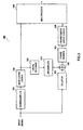
FIG.3 is a block diagram showing the configuration
of an acoustic coding apparatus according to Embodiment
1 of the present invention. An acoustic coding apparatus
100 in FIG.3 is mainly constructed of a downsampler 101,
a base layer coder 102, a local decoder 103, an upsampler
104, a delayer 105, a subtractor 106, a frame divider
107, an enhancement layer coder 108 and a multiplexer
109.
In FIG.3, the downsampler 101 receives input data
(acoustic data) of a sampling rate 2*FH, converts this
input data to a sampling rate 2*FL which is lower than
the sampling rate 2*FH and outputs the input data to the
base layer coder 102.
The base layer coder 102 encodes the input data of
the sampling rate 2*FL in units of a predetermined base
frame and outputs a first coded code which is the coded
input data to the local decoder 103 and multiplexer 109.
For example, the base layer coder 102 encodes the input
data according to a CELP coding.
The local decoder 103 decodes the first coded code
and outputs the decoded signal obtained by the decoding
to the upsampler 104. The upsampler 104 increases the
sampling rate of the decoded signal to 2*FH and outputs
the decoded signal to the subtractor 106.
The delayer 105 delays the input signal by a
predetermined time and outputs the delayed input signal
to the subtractor 106. Setting the length of this delay
to the same value as the time delay produced in the
downsampler 101, base layer coder 102, local decoder 103
and upsampler 104 prevents a phase shift in the next
subtraction processing. For example, suppose this delay
time is the sum total of processing times at the downsampler
101, base layer coder 102, local decoder 103 and upsampler
104. The subtractor 106 subtracts the decoded signal from
the input signal and outputs the subtraction result to
the frame divider 107 as a residual signal.
The frame divider 107 divides the residual signal
into enhancement frames having a shorter time length than
that of the base frame and outputs the residual signal
divided into the enhancement frames to the enhancement
layer coder 108. The enhancement layer coder 108 encodes
the residual signal divided into the enhancement frames
and outputs a second coded code obtained by this coding
to the multiplexer 109. The multiplexer 109 multiplexes
the first coded code and second coded code to output the
multiplexed code.
Next, the operation of the acoustic coding apparatus
according to this embodiment will be explained. Here,
an example where an input signal which is acoustic data
of sampling rate 2*FH is encoded will be explained.
The input signal is converted to the sampling rate
2*FL which is lower than the sampling rate 2*FH by the
downsampler 101. Then, the input signal of the sampling
rate 2*FL is encoded by the base layer coder 102. The
coded input signal is decoded by the local decoder 103
and a decoded signal is generated. The decoded signal
is converted to the sampling rate 2*FH which is higher
than the sampling rate 2*FL by the upsampler 104.
After being delayed by a predetermined time by the
delayer 105, the input signal is output to the subtractor
106. A residual signal is obtained by the subtractor 106
calculating a difference between the input signal which
has passed through the delayer 105 and the decoded signal
converted to the sampling rate 2*FH.
The residual signal is divided by the frame divider
107 into frames having a shorter time length than the
frame unit of coding at the base layer coder 102. The
divided residual signal is encoded by the enhancement
layer coder 108. The coded code generated by the base
layer coder 102 and the coded code generated by the
enhancement layer coder 108 are multiplexed by the
multiplexer 109.
Signals coded by the base layer coder 102 and
enhancement layer coder 108 will be explained below.
FIG. 4 shows an example of the distribution of information
of an acoustic signal. In FIG.4, the vertical axis shows
an amount of information and the horizontal axis shows
a frequency. FIG. 4 shows in which frequency band and how
much speech information, background music and background
noise information included in the input signal exist.
As shown in FIG.4, the speech information has more
information in a low frequency domain and the amount of
information decreases as the frequency increases. On the
other hand, the background music and background noise
information have relatively a smaller amount of low band
information than the speech information and have more
information included in a high band.
Therefore, the base layer encodes the speech signal
with high quality using CELP coding, while the enhancement
layer encodes music in the background and environmental
sound which cannot be expressed by the base layer and
signals of higher frequency components than the frequency
band covered by the base layer efficiently.
FIG.5 shows an example of domains to be coded by
the base layer and enhancement layer. In FIG.5, the
vertical axis shows an amount of information and the
horizontal axis shows a frequency. FIG.5 shows the
domains of information to be coded by the base layer coder
102 and enhancement layer coder 108.
The base layer coder 102 is designed to efficiently
express speech information in the frequency band from
0 to FL and can encode speech information in this domain
with high quality. However, the base layer coder 102 does
not have high coding quality of the background music and
background noise information in the frequency band from
0 to FL.
The enhancement layer coder 108 is designed to cover
the insufficient capacity of the base layer coder 102
explained above and signals in the frequency band from
FL to FH. Therefore, combining the base layer coder 102
and enhancement layer coder 108 can realize coding with
high quality in a wide band.
As shown in FIG.5, since the first coded code
obtained through coding by the base layer coder 102
includes speech information in the frequency band from
0 to FL, it is possible to realize at least the scalable
function whereby a decoded signal is obtained by the first
coded code alone.
The acoustic coding apparatus 100 in this embodiment
sets the time length of a frame coded by this enhancement
layer coder 108 sufficiently shorter than the time length
of a frame coded by the base layer coder 102, and can
thereby shorten delays produced in the enhancement layer.
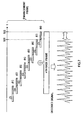
FIG.6 illustrates an example of coding of the base
layer and enhancement layer. In FIG.6, the horizontal
axis shows a time. In FIG.6, an input signal from time
T(n-1) to T(n) is processed as an nth frame. The base
layer coder 102 encodes the nth frame as the nth base
frame which is one base frame. On the other hand, the
enhancement layer coder 108 encodes the nth frame by
dividing it into a plurality of enhancement frames.
Here, the time length of a frame of the enhancement
layer (enhancement frame) is set to 1/J with respect to
the frame of the base layer (base frame). In FIG.6, J=8
is set for convenience, but this embodiment is not limited
to this value and any integer satisfying J≧2 can be used.
The example in FIG. 6 assumes J=8, and therefore eight
enhancement frames correspond to one base frame.
Hereafter, each enhancement frame corresponding to the
nth base frame will be denoted as the nth enhancement
frame (#j) (j=1 to 8). The analysis frame of each
enhancement layer is set so that two successive analysis
frames overlap with each other by half the analysis frame
length to prevent discontinuity from occurring between
the successive frames and subjected to coding processing.
For example, in the nth enhancement frame (#1), the domain
combining frame 401 and frame 402 becomes an analysis
frame. Then, the decoding side decodes the signals
obtained by coding the input signal explained above using
the base layer and the enhancement layer.
FIG. 7 illustrates an example of decoding of the base
layer and enhancement layer. In FIG.7, the horizontal
axis shows a time. In the decoding processing, a decoded
signal of the nth base frame and a decoded signal of the
nth enhancement frames are generated. In the enhancement
layer, it is possible to decode a signal corresponding
to the section in which an overlapping addition with the
preceding frame is possible. In FIG.7, a decoded signal
is generated until time 501, that is, up to the position
of the center of the nth enhancement frame (#8).
That is, according to the acoustic coding apparatus
of this embodiment, the delay produced in the enhancement
layer corresponds to time 501 to time 502, requiring only
1/8 of the time length of the base layer. For example,
when the time length of the base frame is 20 ms, a delay
newly produced in the enhancement layer is 2.5 ms.
This example is the case where the time length of
the enhancement frame is set to 1/8 of the time length
of the base frame, but in general when the time length
of the enhancement frame is set to 1/J of the time length
of the base frame, a delay produced in the enhancement
layer becomes 1/J and it is possible to set J according
to the length of the delay which can be allowed in a system.
Next, the acoustic decoding apparatus which carries
out the above described decoding will be explained. FIG. 8
is a block diagram showing the configuration of an acoustic
decoding apparatus according to Embodiment 1 of the
present invention. An acoustic decoding apparatus 600
in FIG.8 is mainly constructed of a demultiplexer 601,
a base layer decoder 602, an upsampler 603, an enhancement
layer decoder 604, an overlapping adder 605 and an adder
606.
The demultiplexer 601 separates a code coded by the
acoustic coding apparatus 100 into a first coded code
for the base layer and a second coded code for the
enhancement layer, outputs the first coded code to the
base layer decoder 602 and outputs the second coded code
to the enhancement layer decoder 604.
The base layer decoder 602 decodes the first coded
code to obtain a decoded signal having a sampling rate
2*FL. The base layer decoder 602 outputs the decoded
signal to the upsampler 603. The upsampler 603 converts
the decoded signal of the sampling rate 2*FL to a decoded
signal having a sampling rate 2*FH and outputs the
converted signal to the adder 606.
The enhancement layer decoder 604 decodes the second
coded code to obtain a decoded signal having the sampling
rate 2*FH. This second coded code is the code obtained
at the acoustic coding apparatus 100 by coding the input
signal in units of enhancement frames having a shorter
time length than that of the base frame. Then, the
enhancement layer decoder 604 outputs this decoded signal
to the overlapping adder 605.
The overlapping adder 605 overlaps the decoded
signals in units of enhancement frames decoded by the
enhancement layer decoder 604 and outputs the overlapped
decoded signals to the adder 606. More specifically, the
overlapping adder 605 multiplies the decoded signal by
a window function for synthesis, overlaps the decoded
signal with the signal in the time domain decoded in the
preceding frame by half the synthesis frame length and
adds up these signals to generate an output signal.
The adder 606 adds up the decoded signal in the base
layer upsampled by the upsampler 603 and the decoded signal
in the enhancement layer overlapped by the overlapping
adder 605 and outputs the resulting signal.
Thus, according to the acoustic coding apparatus
and acoustic decoding apparatus of this embodiment, the
acoustic coding apparatus side divides a residual signal
in units of the enhancement frame having a shorter time
length than that of the base frame and encodes the divided
residual signal, while the acoustic decoding apparatus
side decodes the residual signal coded in units of the
enhancement frame having a shorter time length than that
of this base frame, overlaps portions having an
overlapping time zone, and it is thereby possible to
shorten the time length of the enhancement frame which
may cause delays during decoding and shorten delays in
speech decoding.
(Embodiment 2)
This embodiment will describe an example where CELP
coding is used for coding of the base layer. FIG.9 is
a block diagram showing an example of the internal
configuration of a base layer coder according to
Embodiment 2 of the present invention. FIG.9 shows the
internal configuration of the base layer coder 102 in
FIG.3. The base layer coder 102 in FIG.9 is mainly
constructed of an LPC analyzer 701, a perceptual weighting
section 702, an adaptive codebook searcher 703, an
adaptive vector gain quantizer 704, a target vector
generator 705, a noise codebook searcher 706, a noise
vector gain quantizer 707 and a multiplexer 708.
The LPC analyzer 701 calculates LPC coefficients
of an input signal of a sampling rate 2*FL and converts
these LPC coefficients to a parameter set suitable for
quantization such as LSP coefficients and quantizes the
parameter set. Then, the LPC analyzer 701 outputs the
coded code obtained by this quantization to the
multiplexer 708.
Furthermore, the LPC analyzer 701 calculates the
quantized LSP coefficients from the coded code, converts
the LSP coefficients to LPC coefficients and outputs the
quantized LPC coefficient to the adaptive codebook
searcher 703, adaptive vector gain quantizer 704, noise
codebook searcher 706 and noise vector gain quantizer
707. Furthermore, the LPC analyzer 701 outputs the LPC
coefficients before quantization to the perceptual
weighting section 702.
The perceptual weighting section 702 assigns a
weight to the input signal output from the downsampler
101 based on both of the quantized and the non-quantized
LPC coefficients obtained by the LPC analyzer 701. This
is intended to perform spectral shaping so that the
spectrum of quantization distortion is masked by a
spectral envelope of the input signal.
The adaptive codebook searcher 703 searches for an
adaptive codebook using the perceptual weighted input
signal as a target signal. The signal obtained by
repeating a past excitation string at pitch periods is
called an "adaptive vector" and an adaptive codebook is
constructed of adaptive vectors generated at pitch
periods within a predetermined range.
When it is assumed that the perceptual weighted input
signal is t (n), a signal obtained by convoluting an impulse
response of a synthesis filter made up of LPC coefficients
into an adaptive vector having a pitch period i is p
i(n),
the
adaptive codebook searcher 703 outputs the pitch
period i of the adaptive vector which minimizes an
evaluation function D in Expression (1) as a parameter
to the
multiplexer 708.
where N denotes a vector length. The first term in
Expression (1) is independent of the pitch period i, and
therefore the
adaptive codebook searcher 703 calculates
only the second term.
The adaptive
vector gain quantizer 704 quantizes
the adaptive vector gain by which the adaptive vector
is multiplied. The adaptive vector gain β is expressed
by the following Expression (2) and the adaptive
vector
gain quantizer 704 scalar-quantizes this adaptive vector
gain β and outputs the code obtained by the quantization
to the
multiplexer 708.
The target vector generator 705 subtracts the
influence of the adaptive vector from the input signal,
generates target vectors to be used in the noise codebook
searcher 706 and noise vector gain quantizer 707 and
outputs the target vectors. In the target vector
generator 705, if it is assumed that pi(n) is a signal
obtained by convoluting an impulse response of a synthesis
filter into an adaptive vector when an evaluation function
D expressed by Expression 1 is a minimum and βq is a
quantized value when the adaptive vector β expressed by
Expression 2 is scalar-quantized, the target vector t2(n)
is expressed by Expression (3) below:
t 2(n)=t(n)-β q ·p i(n)
The noise codebook searcher 706 searches for a noise
codebook using the target vector t2(n) and the quantized
LPC coefficients. For example, a random noise or a signal
learned using a large speech database can be used for
a noise codebook in the noise codebook searcher 706.
Furthermore, the noise codebook provided for the noise
codebook searcher 706 can be expressed by a vector having
a predetermined very small number of pulses of amplitude
1 like an algebraic codebook. This algebraic codebook
is characterized by the ability to determine an optimum
combination of pulse positions and pulse signs
(polarities) by a small amount of calculation.
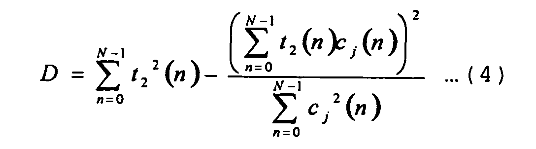
When it is assumed that the target vector is t
2(n)
and a signal obtained by convoluting an impulse response
of a synthesis filter into the noise vector corresponding
to code j is c
j(n), the
noise codebook searcher 706 outputs
the index j of the noise vector that minimizes the
evaluation function D of Expression (4) below to the
multiplexer 708.
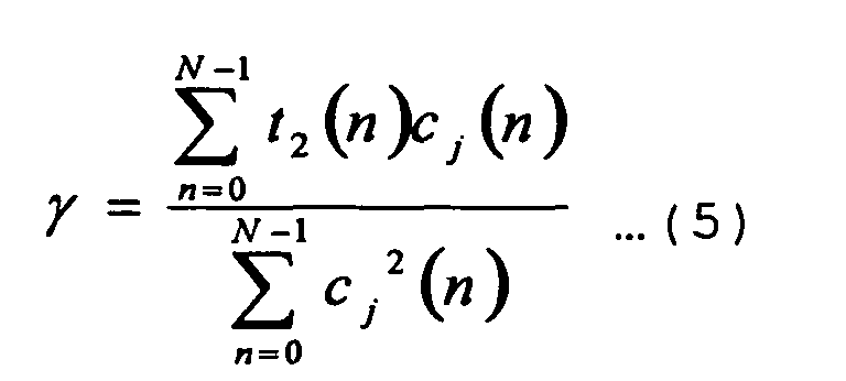
The noise
vector gain quantizer 707 quantizes the
noise vector gain by which the noise vector is multiplied.
The noise
vector gain quantizer 707 calculates a noise
vector gain γ using Expression (5) shown below and
scalar-quantizes this noise vector gain γ and outputs to
the
multiplexer 708.
The multiplexer 708 multiplexes the coded codes of
the quantized LPC coefficients, adaptive vector, adaptive
vector gain, noise vector, and noise vector gain, and
it outputs the multiplexing result to the local decoder
103 and multiplexer 109.
Next, the decoding side will be explained. FIG.10
is a block diagram showing an example of the internal
configuration of a base layer decoder according to
Embodiment 2 of the present invention. FIG.10
illustrates the internal configuration of the base layer
decoder 602 in FIG.8. The base layer decoder 602 in FIG.10
is mainly constructed of a demultiplexer 801, excitation
generator 802 and a synthesis filter 803.
The demultiplexer 801 separates the first coded code
output from the demultiplexer 601 into the coded code
of the quantized LPC coefficients, adaptive vector,
adaptive vector gain, noise vector and noise vector gain,
and it outputs the coded code of the adaptive vector,
adaptive vector gain, noise vector and the noise vector
gain to the excitation generator 802. Likewise, the
demultiplexer 801 outputs the coded code of the quantized
LPC coefficients to the synthesis filter 803.
The excitation generator 802 decodes the coded code
of the adaptive vector, adaptive vector gain, noise vector
and the noise vector gain, and it generates an excitation
vector ex(n) using Expression (6) shown below:
ex(n)=β q ·q(n)+γ q ·c(n)
where q(n) denotes the adaptive vector, βq denotes the
adaptive vector gain, c(n) denotes the noise vector and
γq denotes the noise vector gain.
The
synthesis filter 803 decodes the quantized LPC
coefficients from the coded code of the LPC coefficient
and generates a synthesis signal syn(n) using Expression
(7) shown below:
where α
q denotes the decoded LPC coefficients and NP
denotes the order of the LPC coefficients. The
synthesis
filter 803 outputs the decoded signal syn(n) to the
upsampler 603.
Thus, according to the acoustic coding apparatus
and acoustic decoding apparatus of this embodiment, the
transmitting side encodes an input signal by applying
CELP coding to the base layer and the receiving side applies
the decoding method of the CELP coding to the base layer,
and it is thereby possible to realize a high quality base
layer at a low bit rate.
The speech coding apparatus of this embodiment can
also adopt a configuration with a post filter followed
by the synthesis filter 803 to improve subjective quality.
FIG. 11 is a block diagram showing an example of the internal
configuration of the base layer decoder according to
Embodiment 2 of the present invention. However, the same
components as those in FIG.10 are assigned the same
reference numerals as those in FIG.10 and detailed
explanations thereof will be omitted.
For the post filter 901, various configurations may
be adopted to improve subjective quality. One typical
method is a method using a formant enhanced filter made
up of an LPC coefficient obtained by being decoded by
the demultiplexer 801. A formant emphasis filter Hf(z)
is expressed by Expression (8) shown below:
Hf (z)= A(z/γ n ) A(z/γ d ) ·(1-µz -1)
where 1/A(z) denotes the synthesis filter made up of the
decoded LPC coefficients and γn, γd and µ denote
constants which determine the filter characteristic.
(Embodiment 3)
This embodiment is characterized by the use of
transform coding whereby an input signal of the
enhancement layer is transformed into a coefficient of
the frequency domain and then the transformed
coefficients are encoded. The basic configuration of an
enhancement layer coder 108 according to this embodiment
will be explained using FIG.12. FIG. 12 is a block diagram
showing an example of the internal configuration of an
enhancement layer coder according to Embodiment 3 of the
present invention. FIG.12 shows an example of the
internal configuration of the enhancement layer coder
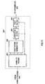
108 in FIG.3. The enhancement layer coder 108 in FIG.12
is mainly constructed of an MDCT section 1001 and a
quantizer 1002.
The
MDCT section 1001 MDCT-transforms (modified
discrete cosine transform) an input signal output from
the
frame divider 107 to obtain MDCT coefficients. An
MDCT transform completely overlaps successive analysis
frames by half the analysis frame length. And the
orthogonal bases of the MDCT consist of "odd functions"
for the first half of the analysis frame and "even
functions" for the second half. In the synthesis process,
the MDCT transform does not generate any frame boundary
distortion because it overlaps and adds up
inverse-transformed waveforms. When an MDCT is
performed, the input signal is multiplied by a window
function such as sine window. When a set of MDCT
coefficients is assumed to be X(n), the MDCT coefficients
can be calculated by Expression (9) shown below:
where X(n) denotes a signal obtained by multiplying the
input signal by the window function.
The quantizer 1002 quantizes the MDCT coefficients
calculated by the MDCT section 1001. More specifically,
the quantizer 1002 scalar-quantizes the MDCT coefficients.
Or a vector is formed by plural MDCT coefficients and
vector-quantized. Especially when scalar quantization
is applied, the above described quantization method tends
to increase the bit rate in order to obtain sufficient
quality. For this reason, this quantization method is
effective when it is possible to allocate sufficient bits
to the enhancement layer. Then, the quantizer 1002
outputs codes obtained by quantizing the MDCT
coefficients to the multiplexer 109.
Next, a method of efficiently quantizing the MDCT
coefficients by mitigating an increase in the bit rate
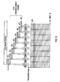
will be explained. FIG.13 shows an example of the
arrangement of the MDCT coefficients. In FIG.13, the
horizontal axis shows a time and the vertical axis shows
a frequency.
The MDCT coefficients to be coded in the enhancement
layer can be expressed by a two-dimensional matrix with
the time direction and frequency direction as shown in
FIG. 13. In this embodiment, eight enhancement frames are
set for one base frame, and therefore the horizontal axis
becomes eight-dimensional and the vertical axis has the
number of dimensions that matches the length of the
enhancement frame. In FIG.13, the vertical axis is
expressed with 16 dimensions, but the number of dimensions
is not limited to this.
Many bits are necessary for quantization to obtain
sufficiently high SNRs for all the MDCT coefficients
expressed in FIG.13. To avoid this problem, the acoustic
coding apparatus of this embodiment quantizes only the
MDCT coefficients included in a predetermined band and
sends no information on other MDCT coefficients. That
is, the MDCT coefficients in a shaded area 1101 in FIG.13
are quantized and other MDCT coefficients are not
quantized.
This quantization method is based on the concept
that the band (0 to FL) to be encoded by the base layer
has already been coded with sufficient quality in the
base layer and has a sufficient amount of information,
and therefore it is only necessary to code other bands
(e.g., FL to FH) in the enhancement layer. Or this
quantization method is based on the concept that coding
distortion tends to increase in the high frequency section
of the band to be coded by the base layer, and therefore
it is only necessary to encode the high frequency section
of the band to be coded by the base layer and the band
not to be coded by the base layer.
Thus, by regarding only the domain that cannot be
covered by coding of the base layer or the domain that
cannot be covered by coding of the base layer and a domain
including part of the band covered by the coding of the
base layer as the coding targets, it is possible to reduce
signals to be coded and achieve the efficient quantization
of MDCT coefficients while mitigating an increase in the
bit rate.
Next, the decoding side will be explained.
Hereafter, a case where an inverse modified discrete
cosine transform (IMDCT) is used as the method of a
transform from the frequency domain to time domain will
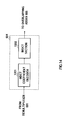
be explained. FIG.14 is a block diagram showing an
example of the internal configuration of an enhancement
layer decoder according to Embodiment 3 of the present
invention. FIG.14 shows an example of the internal
configuration of the enhancement layer decoder 604 in
FIG.8. The enhancement layer decoder 604 in FIG.14 is
mainly constructed of an MDCT coefficient decoder 1201
and an IMDCT section 1202.
The MDCT coefficient decoder 1201 decodes the
quantized MDCT coefficients from the second coded code
output from the demultiplexer 601. The IMDCT section 1202
applies an IMDCT to the MDCT coefficients output from
the MDCT coefficient decoder 1201, generates time domain
signals and outputs the time domain signals to the
overlapping adder 605.
Thus, according to the acoustic coding apparatus
and acoustic decoding apparatus of this embodiment, a
difference signal is transformed from a time domain to
a frequency domain, encodes the frequency domain of the
transformed signal in the enhancement layer which cannot
be covered by the base layer encoding, and can thereby
achieve the effecient coding for a signal having a large
spectral variation such as music.
The band to be coded by the enhancement layer need
not be fixed to FL to FH. The band to be coded in the
enhancement layer changes depending on the characteristic
of the coding method of the base layer and amount of
information included in the high frequency band of the
input signal. Therefore, as explained in Embodiment 2,
in the case where CELP coding for wideband signals is
used for the base layer and the input signal is speech,
it is recommendable to set the band to be encoded by the
enhancement layer to 6 kHz to 9 kHz.
(Embodiment 4)
A human perceptual characteristic has a masking
effect that when a certain signal is given, signals having
frequencies close to the frequency of the signal cannot
be heard. A feature of this embodiment is to find the
perceptual masking based on the input signal and carry
out coding of the enhancement layer using the perceptual
masking.
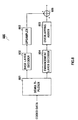
FIG. 15 is a block diagram showing the configuration
of an acoustic coding apparatus according to Embodiment
4 of the present invention. However, the same components
as those in FIG. 3 are assigned the same reference numerals
as those in FIG.3 and detailed explanations thereof will
be omitted. An acoustic coding apparatus 1300 in FIG.15
is provided with a perceptual masking calculation section
1301 and an enhancement layer coder 1302, and is different
from the acoustic coding apparatus in FIG.3 in that it
calculates the perceptual masking from the spectrum of
the input signal and quantizes MDCT coefficients so that
quantization distortion falls below this masking value.
A delayer 105 delays the input signal by a
predetermined time and outputs the delayed input signal
to a subtractor 106 and perceptual masking calculation
section 1301. The perceptual masking calculation
section 1301 calculates perceptual masking indicating
the magnitude of a spectrum which cannot be perceived
by the human auditory sense and outputs the perceptual
masking to the enhancement layer coder 1302. The
enhancement layer coder 1302 encodes a difference signal
of a domain having a spectrum exceeding the perceptual
masking and outputs the coded code of the difference signal
to a multiplexer 109.
Next, details of the perceptual masking calculation
section 1301 will be explained. FIG. 16 is a block diagram
showing an example of the internal configuration of the
perceptual masking calculation section of this embodiment.
The perceptual masking calculation section 1301 in FIG. 16
is mainly constructed of an FFT section 1401, a bark
spectrum calculator 1402, a spread function convoluter
1403, a tonality calculator 1404 and a perceptual masking
calculator 1405.
In FIG.16, the FFT section 1401 Fourier-transforms
the input signal output from the delayer 105 and calculates
Fourier coefficients {Re(m),Im(m)}. Here, m denotes a
frequency.
The
bark spectrum calculator 1402 calculates a bark
spectrum B(k) using Expression (10) shown below:
where P(m) denotes a power spectrum which is calculated
by Expression (11) shown below:
P(m) = Re2(m)+Im2(m)
where Re (m) and Im(m) denote the real part and imaginary
part of a complex spectrum with frequency m, respectively.
Furthermore, k corresponds to the number of the bark
spectrum, FL(k) and FH(k) denote the minimum frequency
(Hz) and maximum frequency (Hz) of the kth bark spectrum,
respectively. Bark spectrum B(k) denotes the intensity
of a spectrum when the spectrum is divided into bands
at regular intervals on the bark scale. When a hertz scale
is expressed as f and bark scale is expressed as B, the
relationship between the hertz scale and the bark scale
is expressed by Expression (12) shown below:
The spread function convoluter 1403 convolutes a
spread function SF(k) into the bark spectrum B(k) to
calculate C (k) .
C(k) = B(k)* SF(k)
The
tonality calculator 1404 calculates spectrum
flatness SFM(k) of each bark spectrum from the power
spectrum P(m) using Expression (14) shown below:
SFM(k)=µg(k)µa(k)
where µg(k) denotes a geometric mean of the kth bark
spectrum and µ a (k) denotes an arithmetic mean of the kth
bark spectrum. The
tonality calculator 1404 calculates
a tonality coefficient α(k) from a decibel value SFM dB (k)
of spectrum flatness SFM(k) using Expression (15) shown
below:
The perceptual masking calculator 1405 calculates
an offset O(k) of each bark scale from the tonality
coefficient α(k) calculated by the tonality calculator
1404 using Expression (16) shown below:
O(k)=α(k)·14.5-k +1.0-α(k)·5.5
Then, the
perceptual masking calculator 1405
subtracts the offset O(k) from the C(k) obtained by the
spread function convoluter 1403 using Expression (17)
shown below to calculate a perceptual masking T(k).
where T
q(k) denotes an absolute threshold. The absolute
threshold denotes a minimum value of perceptual masking
observed as the human perceptual characteristic. The
perceptual masking calculator 1405 transforms the
perceptual masking T(k) expressed on a bark scale into
a hertz scale M (m) and outputs it to the
enhancement layer
coder 1302.
Using the perceptual masking M(m) obtained in this
way, the enhancement layer coder 1302 encodes the MDCT
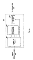
coefficients. FIG.17 is a block diagram showing an
example of the internal configuration of an enhancement
layer coder of this embodiment. The enhancement layer
coder 1302 in FIG.17 is mainly constructed of an MDCT
section 1501 and an MDCT coefficients quantizer 1502.
The MDCT section 1501 multiplies the input signal
output from the frame divider 107 by an analysis window,
MDCT-transforms (modified discrete cosine transform) the
input signal to obtain MDCT coefficients. The MDCT
overlaps successive analysis by half the analysis frame
length. And the orthogonal bases of the MDCT consis of
odd functions for the first half of the analysis frame
and even functions for the second half. In the synthesis
process, the MDCT overlaps the inverse transformed
waveforms and adds up the waveforms, and therefore no
frame boundary distortion occurs. When an MDCT is
performed, the input signal is multiplied by a window
function such as sine window. When the MDCT coefficient
is assumed to be X (n), theMDCT coefficients are calculated
according to Expression (9).
The MDCT coefficient quantizer 1502 uses the
perceptual masking output from the perceptual masking
calculation section 1301 for the MDCT coefficients output
from the MDCT section 1501 to classify the MDCT
coefficients into coefficients to be quantized and
coefficients not to be quantized and encodes only the
coefficients to be quantized. More specifically, the
MDCT coefficient quantizer 1502 compares the MDCT
coefficients X(m) with the perceptual masking M(m) and
ignores the MDCT coefficients X(m) having smaller
intensity than M(m) and excludes them from the coding
targets because such MDCT coefficients X(m) are not
perceived by the human auditory sense due to a perceptual
masking effect and quantizes only the MDCT coefficients
having greater intensity than M(m). Then, the MDCT
coefficient quantizer 1502 outputs the quantized MDCT
coefficients to the multiplexer 109.
Thus, the acoustic coding apparatus of this
embodiment calculates perceptual masking from the
spectrum of the input signal taking advantage of the
characteristic of the masking effect, carries out
quantization during coding of the enhancement layer so
that quantization distortion falls below this masking
value, can thereby reduce the number of MDCT coefficients
to be quantized without causing quality degradation and
realize coding at a low bit rate and with high quality.
The above embodiment has explained the method of
calculating perceptual masking using an FFT, but it is
also possible to calculate the perceptual masking using
an MDCT instead of FFT. FIG.18 is a block diagram showing
an example of the internal configuration of a perceptual
masking calculation section of this embodiment. However,
the same components as those in FIG.16 are assigned the
same reference numerals as those in FIG.16 and detailed
explanations thereof will be omitted.
The MDCT section 1601 approximates a power spectrum
P(m) using MDCT coefficients. More specifically, the
MDCT section 1601 approximates P (m) using Expression (18)
below:
P(m)=R 2(m)
where R(m) denotes an MDCT coefficient obtained by
MDCT-transforming the input signal.
The bark spectrum calculator 1402 calculates a bark
spectrum B(k) from P(m) approximated by the MDCT section
1601. From then on, perceptual masking is calculated
according to the above described method.
(Embodiment 5)
This embodiment relates to the enhancement layer
coder 1302 and a feature thereof is that it relates to
a method of efficiently coding position information on
MDCT coefficients when MDCT coefficients exceeding
perceptual masking are quantization targets.
FIG.19 is a block diagram showing an example of the
internal configuration of an enhancement layer coder
according to Embodiment 5 of the present invention.
FIG.19 shows an example of the internal configuration
of the enhancement layer coder 1302 in FIG.15. The
enhancement layer coder 1302 in FIG.19 is mainly
constructed of an MDCT section 1701, a quantization
position determining section 1702, an MDCT coefficient
quantizer 1703, a quantization position coder 1704 and
a multiplexer 1705.
The MDCT section 1701 multiplies the input signal
output from the frame divider 107 by an analysis window
and then MDCT-transforms (modified discrete cosine
transform) the input signal to obtain MDCT coefficients.
The MDCT transform is performed by overlapping successive
frames by half the analysis frame length and uses
orthogonal bases of odd functions for the first half of
the analysis frame and even functions for the second half.
In the synthesis process, the MDCT transform overlaps
the inverse transformed waveforms and adds up the
waveforms, and therefore no frame boundary distortion
occurs. When the MDCT is performed, the input signal is
multiplied by a window function such as sine window. When
MDCT coefficients are assumed to be X(n), the MDCT
coefficients are calculated according to Expression (9).
The MDCT coefficient calculated by the MDCT section
1701 is expressed as X(j,m). Here, j denotes the frame
number of an enhancement frame and m denotes a frequency.
This embodiment will explain a case where the time length
of the enhancement frame is 1/8 of the time length of
the base frame. FIG.20 shows an example of the
arrangement of MDCT coefficients. An MDCT coefficient
X(j,m) can be expressed on a matrix whose horizontal axis
shows a time and whose vertical axis shows a frequency
as shown in FIG.20. The MDCT section 1701 outputs the
MDCT coefficient X(j,m) to the quantization position
determining section 1702 and MDCT coefficients
quantization section 1703.
The quantization position determining section 1702
compares the perceptual masking M(j,m) output from the
perceptual masking calculation section 1301 with the MDCT
coefficient X(j,m) output from the MDCT section 1701 and
determines which positions of MDCT coefficients are to
be quantized.
More specifically, when Expression (19) shown below
is satisfied, the quantization position determining
section 1702 quantizes X(j,m).
X(j,m)-M(j,m)>0
Then, when Expression (20) is satisfied, the
quantization position determining section 1702 does not
quantize X(j,m).
X(j,m)-M(j,m)≤0
Then, the quantization position determining section
1702 outputs the position information on the MDCT
coefficient X(j,m) to be quantized to the MDCT
coefficients quantization section 1703 and quantization
position coder 1704. Here, the position information
indicates a combination of time j and frequency m.
In FIG.20, the positions of the MDCT coefficients
X(j,m) to be quantized determined by the quantization
position determining section 1702 are expressed by shaded
areas. In this example, the MDCT coefficients X (j,m) at
positions (j,m) = (6,1), (5,3), ···, (7,15), (5,16) are
quantization targets.
Here, suppose the perceptual masking M(j,m) is
calculated by being synchronized with the enhancement
frame. However, because of restrictions on the amount
of calculation, etc., it is also possible to calculate
perceptual masking M(j,m) in synchronization with the
base frame. In this case, compared to the case where
perceptual masking is synchronized with the enhancement
frame, the amount of calculation of perceptual masking
is reduced to 1/8. Furthermore, in this case, the
perceptual masking is obtained by the base frame first
and then the same perceptual masking is used for all
enhancement frames.
The MDCT coefficients quantization section 1703
quantizes the MDCT coefficients X(j,m) at the positions
determined by the quantization position determining
section 1702. When performing quantization, the MDCT
coefficients quantization section 1703 uses information
on the perceptual masking M(j,m) and performs
quantization so that the quantization error falls below
the perceptual masking M(j,m). When the quantized MDCT
coefficients are assumed to be X'(j,m), the MDCT
coefficients quantization section 1703 performs
quantization so as to satisfy Expression (21) shown below.
X(j,m)-X'(j,m)≤M(j,m)
Then, the MDCT coefficients quantization section
1703 outputs the quantized codes to the multiplexer 1705.
The quantization position coder 1704 encodes the
position information. For example, the quantization
position coder 1704 encodes the position information
using a run-length coding method. The quantization
position coder 1704 scans from the lowest frequency in
the time-axis direction and performs coding in such a
way that the number of positions in which coefficients
to be coded do not exist continuously and the number of
positions in which coefficients to be coded exist
continuously are regarded as the position information.
More specifically, the quantization position coder
1704 scans from (j,m)=(1,1) in the direction in which
j increases and performs coding using the number of
positions until the coefficient to be coded appears as
the position information.
In FIG.20, the distance from (j,m)=(1,1) to the
position (j,m)=(1,6) of the coefficient which becomes
the first coding target is 5, and then, since only one
coefficient to be coded exists continuously, the number
of positions in which coefficients to be coded exist
continuously is 1, and then the number of positions in
which coefficients not to be coded exist continuously
is 14. In this way, in FIG.20, codes expressing position
information are 5, 1, 14, 1, 4, 1, 4···, 5, 1, 3. The
quantization position coder 1704 outputs this position
information to the multiplexer 1705. The multiplexer
1705 multiplexes the information on the quantization of
the MDCT coefficients X(j,m) and position information
and outputs the multiplexing result to the multiplexer
109.
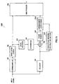
Next, the decoding side will be explained. FIG.21
is a block diagram showing an example of the internal
configuration of an enhancement layer decoder according
to Embodiment 5 of the present invention. FIG.21 shows
an example of the internal configuration of the
enhancement layer decoder 604 in FIG.8. The enhancement
layer decoder 604 in FIG.21 is mainly constructed of a
demultiplexer 1901, an MDCT coefficients decoder 1902,
a quantization position decoder 1903, a time-frequency
matrix generator 1904 and an IMDCT section 1905.
The demultiplexer 1901 separates a second coded code
output from the demultiplexer 601 into MDCT coefficient
quantization information and quantization position
information, outputs the MDCT coefficient quantization
information to the MDCT coefficient decoder 1902 and
outputs the quantization position information to the
quantization position decoder 1903.
The MDCT coefficient decoder 1902 decodes the MDCT
coefficients from the MDCT coefficient quantization
information output from the demultiplexer 1901 and
outputs the decoded MDCT coefficients to the
time-frequency matrix generator 1904.
The quantization position decoder 1903 decodes the
quantization position information from the quantization
position information output from the demultiplexer 1901
and outputs the decoded quantization position information
to the time-frequency matrix generator 1904. This
quantization position information is the information
indicating the positions of the decodedMDCT coefficients
in the time-frequency matrix.
The time-frequency matrix generator 1904 generates
the time-frequency matrix shown in FIG.20 using the
quantization position information output from the
quantization position decoder 1903 and the decoded MDCT
coefficients output from the MDCT coefficient decoder
1902. FIG.20 shows the positions at which the decoded
MDCT coefficients exist with shaded areas and shows the
positions at which the decoded MDCT coefficients do not
exist with white areas. At the positions in the white
areas, no decoded MDCT coefficients exist, and therefore
0s are provided as the decoded MDCT coefficients.
Then, the time-frequency matrix generator 1904
outputs the decodedMDCT coefficients to the IMDCT section
1905 for every enhancement frame (j=1 to J). The IMDCT
section 1905 applies an IMDCT to the decoded MDCT
coefficients, generates a signal in the time domain and
outputs the signal to the overlapping adder 605.
Thus, the acoustic coding apparatus and acoustic
decoding apparatus of this embodiment transforms a
residual signal from a time domain to a frequency domain
during coding in the enhancement layer, and then performs
perceptual masking to determine the coefficients to be
coded and encodes the two-dimensional position
information on a frequency and a frame number, and can
thereby reduce an amount of information on positions
taking advantage of the fact the positions of coefficients
to be coded and coefficients not to be coded are continuous
and perform coding at a low bit rate and with high quality.
(Embodiment 6)
FIG.22 is a block diagram showing an example of the
internal configuration of an enhancement layer coder
according to Embodiment 6 of the present invention.
FIG.22 shows an example of the internal configuration
of the enhancement layer coder 1302 in FIG.15. However,
the same components as those in FIG.19 are assigned the
same reference numerals as those in FIG.19 and detailed
explanations thereof will be omitted. The enhancement
layer coder 1302 in FIG. 22 is provided with a domain divider
2001, a quantization domain determining section 2002,
an MDCT coefficients quantization section 2003 and a
quantization domain coder 2004 and relates to another
method of efficiently coding position information on MDCT
coefficients when MDCT coefficients exceeding perceptual
masking are quantization targets.
The domain divider 2001 divides MDCT coefficients
X(j,m) obtained by the MDCT section 1701 into plural
domains. The domain here refers to a set of positions
of plural MDCT coefficients and is predetermined as
information common to both the coder and decoder.
The quantization domain determining section 2002
determines domains to be quantized. More specifically,
when a domain is expressed as S(k)(k=1 to K), the
quantization domain determining section 2002 calculates
the sum total of the amounts by which these MDCT
coefficients X(j,m) exceed perceptual masking M(m)
included in the domain S (k) and selects K' (K'<K) domains
in descending order in the magnitude of this sum total.
FIG.23 shows an example of the arrangement of MDCT
coefficients. FIG. 23 shows an example of the domain S (k).
The shaded areas in FIG.23 denote the domains to be
quantized determined by the quantization domain
determining section 2002. In this example, the domain
S(k) is a rectangle which is four-dimensional in the
time-axis direction and two-dimensional in the
frequency-axis direction and the quantization targets
are four domains of S(6), S(8), S(11) and S(14).
As described above, the quantization
domain
determining section 2002 determines which domains S(k)
should be quantized according to the sum total of amounts
by which the MDCT coefficients X(j,m) exceed perceptual
masking M(j,m). The sum total V(k) is calculated by
Expression (22) below:
According to this method, high frequency domains V(k)
may be hardly selected depending on the input signal.
Therefore, insteadof Expression (22), it is also possible
to use a method of normalizing with intensity of MDCT
coefficients X(j,m) expressed in Expression (23) shown
below:
Then, the quantization domain determining section
2002 outputs information on the domains to be quantized
to the MDCT coefficients quantization section 2003 and
quantization domain coder 2004.
The quantization domain coder 2004 assigns code 1
to domains to be quantized and code 0 to other domains
and outputs the codes to the multiplexer 1705. In the
case of FIG.23, the codes become 0000, 0101, 0010, 0100.
Furthermore, this code can also be expressed using a
run-length coding method. In that case, the codes
obtained are 5, 1, 1, 1, 2, 1, 2, 1, 2.
The MDCT coefficients quantization section 2003
quantizes the MDCT coefficients included in the domains
determined by the quantization domain determining section
2002. As a method of quantization, it is also possible
to construct one or more vectors from the MDCT coefficients
included in the domains and perform vector quantization.
In performing vector quantization, it is also possible
to use a scale weighted by perceptual masking M(j,m).
Next, the decoding side will be explained. FIG.24
is a block diagram showing an example of the internal
configuration of an enhancement layer decoder according
to Embodiment 6 of the present invention. FIG.24 shows
an example of the internal configuration of the
enhancement layer decoder 604 in FIG.8. The enhancement
layer decoder 604 in FIG.24 is mainly constructed of a
demultiplexer 2201, an MDCT coefficient decoder 2202,
a quantization domain decoder 2203, a time-frequency
matrix generator 2204 and an IMDCT section 2205.
A feature of this embodiment is the ability to decode
coded codes generated by the aforementioned enhancement
layer coder 1302 of Embodiment 6.
The demultiplexer 2201 separates a second coded code
output from the demultiplexer 601 into MDCT coefficient
quantization information and quantization domain
information, outputs the MDCT coefficient quantization
information to the MDCT coefficient decoder 2202 and
outputs the quantization domain information to the
quantization domain decoder 2203.
The MDCT coefficient decoder 2202 decodes the MDCT
coefficients from the MDCT coefficient quantization
information obtained from the demultiplexer 2201. The
quantization domain decoder 2203 decodes the quantization
domain information from the quantization domain
information obtained from the demultiplexer 2201. This
quantization domain information is information
expressing to which domain in the time frequency matrix
the respective decoded MDCT coefficients belong.
The time-frequency matrix generator 2204 generates
a time-frequency matrix shown in FIG.23 using the
quantization domain information obtained from the
quantization domain decoder 2203 and the decoded MDCT
coefficients obtained from the MDCT coefficient decoder
2202. In FIG.23, the domains where decoded MDCT
coefficients exist are expressed by shaded areas and
domains where no decoded MDCT coefficients exist are
expressed by white areas. The white areas provide 0s as
decoded MDCT coefficients because no decoded MDCT
coefficients exist.
Then, the time-frequency matrix generator 2204
outputs a decoded MDCT coefficient for every enhancement
frame (j=1 to J) to the IMDCT section 2205. The IMDCT
section 2205 applies an IMDCT to the decoded MDCT
coefficients, generates signals in the time domain and
outputs the signals to the overlapping adder 605.
Thus, the acoustic coding apparatus and acoustic
decoding apparatus of this embodiment set position
information of the time domain and the frequency domain
in which residual signals exceeding the perceptual
masking exist in group units (domains), and can thereby
express the positions of domains to be coded with fewer
bits and realize a low bit rate.
(Embodiment 7)
Next, Embodiment 7 will be explained with reference
to the attached drawings. FIG.25 is a block diagram
showing the configuration of a communication apparatus
according to Embodiment 7 of the present invention. This
embodiment is characterized in that the signal processing
apparatus 2303 in FIG.25 is constructed of one of the
aforementioned acoustic coding apparatuses shown in
Embodiment 1 to Embodiment 6.
As shown in FIG.25, a communication apparatus 2300
according to Embodiment 7 of the present invention is
provided with an input apparatus 2301, an A/D conversion
apparatus 2302 and a signal processing apparatus 2303
connected to a network 2304.
The A/D conversion apparatus 2302 is connected to
the output terminal of the input apparatus 2301. The
input terminal of the signal processing apparatus 2303
is connected to the output terminal of the A/D conversion
apparatus 2302. The output terminal of the signal
processing apparatus 2303 is connected to the network
2304.
The input apparatus 2301 converts a sound wave
audible to the human ears to an analog signal which is
an electric signal and gives it to the A/D conversion
apparatus 2302. The A/D conversion apparatus 2302
converts the analog signal to a digital signal and gives
it to the signal processing apparatus 2303. The signal
processing apparatus 2303 encodes the digital signal
input, generates a code and outputs the code to the network
2304.
In this way, the communication apparatus according
to this embodiment of the present invention can provide
an acoustic coding apparatus capable of realizing the
effects shown in Embodiments 1 to 6 and efficiently coding
acoustic signals with fewer bits.
(Embodiment 8)
Next, Embodiment 8 of the present invention will
be explained with reference to the attached drawings.
FIG.26 is a block diagram showing the configuration of
a communication apparatus according to Embodiment 8 of
the present invention. This embodiment is characterized
in that the signal processing apparatus 2403 in FIG.26
is constructed of one of the aforementioned acoustic
decoding apparatuses shown in Embodiment 1 to Embodiment
6.
As shown in FIG.26, the communication apparatus 2400
according to Embodiment 8 of the present invention is
provided with a reception apparatus 2402 connected to
a network 2401, a signal processing apparatus 2403, a
D/A conversion apparatus 2404 and an output apparatus
2405.
The input terminal of the reception apparatus 2402
is connected to a network 2401. The input terminal of
the signal processing apparatus 2403 is connected to the
output terminal of the reception apparatus 2402. The
input terminal of the D/A conversion apparatus 2404 is
connected to the output terminal of the signal processing
apparatus 2403. The input terminal of the output
apparatus 2405 is connected to the output terminal of
the D/A conversion apparatus 2404.
The reception apparatus 2402 receives a digital
coded acoustic signal from the network 2401, generates
a digital received acoustic signal and gives it to the
signal processing apparatus 2403. The signal processing
apparatus 2403 receives the received acoustic signal from
the reception apparatus 2402, applies decoding processing
to this received acoustic signal, generates a digital
decoded acoustic signal and gives it to the D/A conversion
apparatus 2404. The D/A conversion apparatus 2404
converts the digital decoded speech signal from the signal
processing apparatus 2403, generates an analog decoded
speech signal and gives it to the output apparatus 2405.
The output apparatus 2405 converts the analog decoded
acoustic signal which is an electric signal to vibration
of the air and outputs it as sound wave audible to the
human ears.
Thus, the communication apparatus of this
embodiment can realize the aforementioned effects in
communications shown in Embodiments 1 to 6, decode coded
acoustic signals efficiently with fewer bits and thereby
output a high quality acoustic signal.
(Embodiment 9)
Next, Embodiment 9 of the present invention will
be explained with reference to the attached drawings.
FIG.27 is a block diagram showing the configuration of
a communication apparatus according to Embodiment 9 of
the present invention. Embodiment 9 of the present
invention is characterized in that the signal processing
apparatus 2503 in FIG.27 is constructed of one of the
aforementioned acoustic coding sections shown in
Embodiment 1 to Embodiment 6.
As shown in FIG. 27, the communication apparatus 2500
according to Embodiment 9 of the present invention is
provided with an input apparatus 2501, an A/D conversion
apparatus 2502, a signal processing apparatus 2503, an
RF modulation apparatus 2504 and an antenna 2505.
The input apparatus 2501 converts a sound wave
audible to the human ears to an analog signal which is
an electric signal and gives it to the A/D conversion
apparatus 2502. The A/D conversion apparatus 2502
converts the analog signal to a digital signal and gives
it to the signal processing apparatus 2503. The signal
processing apparatus 2503 encodes the input digital
signal, generates a coded acoustic signal and gives it
to the RF modulation apparatus 2504. The RF modulation
apparatus 2504 modulates the coded acoustic signal,
generates a modulated coded acoustic signal and gives
it to the antenna 2505. The antenna 2505 sends the
modulated coded acoustic signal as a radio wave.
Thus, the communication apparatus of this
embodiment can realize the aforementioned effects in a
radio communication as shown in Embodiments 1 to 6 and
efficiently encode an acoustic signal with fewer bits.
The present invention is applicable to a
transmission apparatus, transmission coding apparatus
or acoustic signal coding apparatus using an audio signal.
Furthermore, the present invention is also applicable
to a mobile station apparatus or base station apparatus.
(Embodiment 10)
Next, Embodiment 10 of the present invention will
be explained with reference to the attached drawings.
FIG.28 is a block diagram showing the configuration of
a communication apparatus according to Embodiment 10 of
the present invention. Embodiment 10 of the present
invention is characterized in that the signal processing
apparatus 2603 in FIG.28 is constructed of one of the
aforementioned acoustic decoding sections shown in
Embodiment 1 to Embodiment 6.
As shown in FIG.28, the communication apparatus 2600
according to Embodiment 10 of the present invention is
provided with an antenna 2601, an RF demodulation
apparatus 2602, a signal processing apparatus 2603, a
D/A conversion apparatus 2604 and an output apparatus
2605.
The antenna 2601 receives a digital coded acoustic
signal as a radio wave, generates a digital received coded
acoustic signal which is an electric signal and gives
it to the RF demodulation apparatus 2602. The RF
demodulation apparatus 2602 demodulates the received
coded acoustic signal from the antenna 2601, generates
a demodulated coded acoustic signal and gives it to the
signal processing apparatus 2603.
The signal processing apparatus 2603 receives the
digital demodulated coded acoustic signal from the RF
demodulation apparatus 2602, carries out decoding
processing, generates a digital decoded acoustic signal
and gives it to the D/A conversion apparatus 2604. The
D/A conversion apparatus 2604 converts the digital
decoded speech signal from the signal processing
apparatus 2603, generates an analog decoded speech signal
and gives it to the output apparatus 2605. The output
apparatus 2605 converts the analog decoded speech signal
which is an electric signal to vibration of the air and
outputs it as a sound wave audible to the human ears.
Thus, the communication apparatus of this
embodiment can realize the aforementioned effects in a
radio communication as shown in Embodiments 1 to 6, decode
a coded acoustic signal efficiently with fewer bits and
thereby output a high quality acoustic signal.
The present invention is applicable to a reception
apparatus, reception decoding apparatus or speech signal
decoding apparatus using an audio signal. Furthermore,
the present invention is also applicable to a mobile
station apparatus or base station apparatus.
Furthermore, the present invention is not limited
to the above embodiments, but can be implemented modified
in various ways. For example, the above embodiments have
described the case where the present invention is
implemented as a signal processing apparatus, but the
present invention is not limited to this and this signal
processing method can also be implemented by software.
For example, it is possible to store a program for
executing the above described signal processing method
in a ROM (Read Only Memory) beforehand and operate the
program by a CPU (Central Processor Unit).
Furthermore, it is also possible to store a program
for executing the above described signal processing
method in a computer-readable storage medium, record the
program stored in the storage medium in a RAM (Random
Access memory) of a computer and operate the computer
according to the program.
The above described explanations have described the
case where an MDCT is used as the method of transform
from a time domain to a frequency domain, but the present
invention is not limited to this and any method is
applicable if it provides at least an orthogonal transform.
For example, a discrete Fourier transform or discrete
cosine transform, etc., can be used.
The present invention is applicable to a reception
apparatus, reception decoding apparatus or speech signal
decoding apparatus using an audio signal. Furthermore,
the present invention is also applicable to a mobile
station apparatus or base station apparatus.
As is evident from the above described explanations,
the acoustic coding apparatus and acoustic coding method
of the present invention encodes an enhancement layer
with the time length of a frame in the enhancement layer
set to be shorter than the time length of a frame in the
base layer, and can thereby code even a signal which
consists predominantly of speech with music and noise
superimposed in the background, with a short delay, at
a low bit rate and with high quality.
This application is based on the Japanese Patent
Application No. 2002-261549 filed on September 6, 2002,
entire content of which is expressly incorporated by
reference herein.
Industrial Applicability
The present invention is preferably applicable to
an acoustic coding apparatus and a communication
apparatus which efficiently compresses and encodes an
acoustic signal such as a music signal or speech signal.