EP1533680A2 - Server system and signal processing unit, server, and chassis thereof - Google Patents
Server system and signal processing unit, server, and chassis thereof Download PDFInfo
- Publication number
- EP1533680A2 EP1533680A2 EP04257033A EP04257033A EP1533680A2 EP 1533680 A2 EP1533680 A2 EP 1533680A2 EP 04257033 A EP04257033 A EP 04257033A EP 04257033 A EP04257033 A EP 04257033A EP 1533680 A2 EP1533680 A2 EP 1533680A2
- Authority
- EP
- European Patent Office
- Prior art keywords
- server
- processing unit
- blade
- signal processing
- slots
- Prior art date
- Legal status (The legal status is an assumption and is not a legal conclusion. Google has not performed a legal analysis and makes no representation as to the accuracy of the status listed.)
- Granted
Links
Images


Classifications
-
- G—PHYSICS
- G06—COMPUTING OR CALCULATING; COUNTING
- G06F—ELECTRIC DIGITAL DATA PROCESSING
- G06F1/00—Details not covered by groups G06F3/00 - G06F13/00 and G06F21/00
- G06F1/16—Constructional details or arrangements
- G06F1/18—Packaging or power distribution
- G06F1/189—Power distribution
-
- G—PHYSICS
- G06—COMPUTING OR CALCULATING; COUNTING
- G06F—ELECTRIC DIGITAL DATA PROCESSING
- G06F1/00—Details not covered by groups G06F3/00 - G06F13/00 and G06F21/00
- G06F1/16—Constructional details or arrangements
- G06F1/18—Packaging or power distribution
- G06F1/183—Internal mounting support structures, e.g. for supporting printed circuit boards
Definitions
- This invention generally relates to a server system and a signal processing unit, a server, and a chassis thereof that enable to operate at least one server with a set of console.
- FIG. 1 shows an example of a remote control system with the use of the above-mentioned conventional technique.
- the system architecture shown in Fig. 1 includes multiple groups of servers 910. Each group is composed of a chassis on which multiple servers 911 are mounted.
- the servers 911 are connected to a server switching unit 901 via connectors for outputting display images such as VGA (Video Graphics Array) connector, keyboard connector, mouse connector such as PS/2® connector, or the like.
- VGA Video Graphics Array
- keyboard connector keyboard connector
- mouse connector such as PS/2® connector
- the server switching unit 901 is connected to a network 903 such as a LAN (Local Area Network), the Internet, or the like.
- a network 903 such as a LAN (Local Area Network), the Internet, or the like.
- the server switching unit 901 is configured to communicate with an information processing device 920 such as a personal computer (hereinafter simply referred to as PC), a workstation, or the like.
- PC personal computer
- the server switching unit 901 upon request of the information processing device 920, selectively connects the information processing device 920 to the requested server 911.
- the server switching unit 901 generates, for example, an IP (Internet Protocol) packet based on a displayed image outputted from the VGA connector of the server 911, and sends the IP packet to the information processing device 920.
- the information processing device 920 receives the IP packet from the network 903 based on an IP address, and displays the image displayed on the server 911 on a monitor 921.
- the information processing device 920 also converts instructional information inputted with a keyboard or mouse in response to the above-mentioned displayed image into an IP packet, and sends the IP packet to the server switching unit 901.
- the server switching unit 901 receives the IP packet including the instructional information from the network 903 based on the IP address, extracts the instructional information, and outputs the instructional information to the keyboard connector or the mouse connector of the server 911.
- the server switching unit 901 makes the information processing unit 920 serve as an input/output device for the monitor, keyboard, mouse or the like connected to a selected server 911. This allows the operator to operate the above-mentioned input/output device as if the input/output device were directly connected to the server 911.
- the servers 911 are respectively connected to the network 903, in addition to being respectively connected to the server switching unit 901. That is, the servers 911 are equipped with network adapters.
- a server system including at least one server, a signal processing unit that enables to operate said at least one server with a set of console, and a chassis having slots and a circuit board, said at least one server or the signal processing unit being attachable and detachable to any of the slots, the circuit board having interconnection lines connecting the slots, said at least one server and the signal processing unit being connected via an interface that allows plug and play connectivity.
- a signal processing unit including a first circuit having an interface that allows plug and play connectivity, and a second circuit connectable to a server system via the first circuit, the server system having slots that are provided to a chassis and are connected together via interconnection lines, a server being any of the slots.
- a server including a connector that allows the server to be inserted into any of slots that are provided to a chassis of a server system and are mutually connected via interconnection lines, and an interface circuit connected to a signal processing unit that is inserted into one of the slots and has an interface that allows the server to be connected to the signal processing unit with plug and play connectivity.
- a chassis including a circuit board having slots into which servers can be inserted, and interconnection lines that are provided to the circuit board and connects the slots, the servers being connected, via the interconnection lines, to a signal processing unit having an interface that enables to operate the servers with a single set of console.
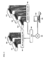
- FIG. 2 shows architecture of a server system 1.
- the server system 1 includes at least one blade chassis 10 having at least one blade server 11.
- the blade server 11 includes a network adapter, as will be described later in detail, and a jack on the font side or back side thereof so that a LAN cable or the like may be connected to.
- the blade server 11 is connected to a LAN 40 via the above-mentioned LAN cable.
- the blade server 11 may be connected to various types of networks such as a WAN (Wide Area Network) or the Internet.
- the LAN 40 includes, for example, a HUB 41 that serves as a relay node.
- the HUB 41 propagates IP packets that are communicated among connected servers and clients.
- a PC 30 is connected to the LAN 40 as a client terminal, in accordance with the first embodiment of the present invention.
- the blade chassis 10 which will be described later in detail, includes slots 105 and 106, into which the blade server 11 and a KVM (Keyboard-Video-Mouse) device 12 may be respectively inserted.
- the blade chassis 10 also includes a circuit board (a backplane 107) having interconnection lines 108 that respectively connect the blade servers 11 and the KVM device 12.
- the KVM device 12 may be inserted into and removed from the blade chassis 10 on which the blade servers 11 are mounted. Therefore, the interconnection lines 108, which connect the blade servers 11 and the KVM device 12, may also be mounted on the blade chassis 10. This makes it possible to readily connect the blade servers 11 and the KVM device 12 without an external cable or the like.
- the KVM device 12 is a signal processing unit that connects an input/output device and a display device to any one of the blade servers 11.
- the input/output device denotes a keyboard or a mouse.
- the display device denotes a monitor.
- the KVM device 12, as will be described later in detail, is connected to at least one blade server 11 via a backplane 107 on the blade chassis 10.
- the KVM 12 is capable of locally connecting a local KVM 20 having a keyboard 21, a mouse 22, and a monitor 23.
- "K" for KVM denotes keyboard
- V denotes monitor
- M denotes mouse.
- the local KVM 20 is a set of console that is used for operating the blade servers 11.
- the KVM device 12 inputs data applied from the keyboard 21 or the mouse 22, into the blade server 11.
- the data includes, for example, a keyboard signal (hereinafter simply referred to as K signal) or a mouse signal (hereinafter simply referred to as M signal).
- K signal is generated by the keyboard 21 based on a user's manipulation.
- M signal is generated by the mouse 22 based on the user's manipulation.
- the KVM device 12 applies data that is outputted from the blade server 11 to the keyboard 21, the mouse 22, or the monitor 23.
- the data includes a command that the blade server 11 gives instructions to the keyboard 21 or the mouse 22 and a video signal (hereinafter simply referred to as V signal) that the blade server 11 displays on an output screen such as a console screen or a GUI (graphical User Interface) screen.
- V signal video signal
- the KVM device 12 controls input and output of various types of data based on the request from a user.
- the KVM device 12 inputs the data from the keyboard 21 or the mouse 22 into any one of the blade servers 11 that is selected by the user. Also, the KVM device 12 inputs the data from any one of the blade servers 11 that the user selects, into the keyboard 21, the mouse 22, or the monitor 23.
- the KVM 12 it is possible to realize a computing environment as if the keyboard 21, the mouse 22, and the monitor 23 were directly connecting to the selected blade server 11.
- another KVM device that is provided with the PC 30 to manipulate the blade server 11 as a set of console, in accordance with the first embodiment of the present invention. That is, the user is able to operate the blade server 11 with the PC 30, in accordance with the first embodiment of the present invention.
- the KVM device 12 is equipped with a network adapter, as will be described later in detail, and a jack on the front or back side thereof so as to connect a LAN cable or the like.
- the KVM device 12 it is also possible to realize another computing environment that the selected blade server 11 may be operated with the PC 30 by sending and receiving data to and from the PC 30 via the LAN 40.
- Fig. 3 is a block diagram showing structures of the blade chassis 10, the blade server 11, and the KVM device 12.
- the blade chassis 10 includes three blade servers, 11a, 11b, and 11c.
- the blade server 11a includes a circuit board on which a server structure 111a, a USB (Universal Serial Bus) microcomputer 112a, a switch (SW) 113a are mounted.
- the server structure 111a, the USB microcomputer 112a, and the switch 113a are interconnected via a bus provided on the circuit board.
- Other blade servers 11b and 11c have the same configurations. Therefore, the blade server 11a will be described below.
- the server structure 111a includes a K/M signal processing unit 114a, a V signal processing unit 115a, and a network adapter 116a, in addition to a CPU (Central Processing Unit), a memory, and a hard disc. Aforementioned components are included in a general server.
- the network adapter 116a is used for connecting the server structure 111a independently to the LAN 40.
- the network adapter 116a is equipped with a jack into which a LAN cable is plugged.
- the K/M signal processing unit 114a processes inputted K signal or M signal as instructional information from the user, and outputs the instructional information into the CPU in the server structure 111a.
- the K signal or the M signal (hereinafter referred to as K/M signal) is inputted into the K/M signal processing unit 114a from the KVM device 12 via the USB microcomputer 112a.
- the K/M signal processing unit 114a outputs a command for setting up the keyboard or mouse. This command may be generated by the K/M signal processing unit 114a or another component of the server structure 111a such as the CPU 121.
- the command outputted from the K/M signal processing unit 114a is inputted into the KVM device 12 via the USB microcomputer 112a.
- the KVM device 12 outputs the inputted command into the keyboard or mouse as necessary, or sends the command to the PC 30 that is connected via the LAN 40.
- the V signal processing unit 115a outputs an output screen of the blade server 11a as a V signal of RGB (Red/Green/Blue) method or DVI (Digital Visual Interface) method.
- the RGB method may employ analogue or digital method.
- the RGB method will be described below.
- the V signal processing unit 115a outputs both horizontal and vertical synchronizing signals. Therefore, in the description below, the above-mentioned signals will be included in the V signal.
- the V signal outputted from the V signal processing unit 115a is applied to the KVM device 12 via the switch 113a.
- the KVM device 12 generates an image of the output screen, based on the applied V signal, and displays the image as necessary or as required or sends to the PC 30 connected via the LAN 40. This image is displayed on the monitor 23 or a monitor 31 as OSD (On Screen Display).
- the USB microcomputer 112a incorporates a USB interface circuit that allows plug and play connectivity, and controls an interface that connects the blade server 11a and the KVM device 12.
- the blade server 11a and the KVM device 12 are thus connected with the interface that enables plug and play connectivity such as the above-mentioned USB interface. Therefore, it is no longer necessary to power off other blade servers, the KVM device 12, or the blade chassis 10 when the blade server 11a is inserted or removed.
- the interface that allows plug and play connectivity is readily able to control the situation when the blade server 11 is newly activated. Further, it is possible to switch from any one of the blade servers 11 to another one immediately, by employing the interface that allows plug and play connectivity.
- the USB microcomputer 112a may be replaced by another microcomputer that incorporates another bus interface circuit, if the interface enables plug and play connectivity.
- the USB microcomputer 112a inputs the K/M signal into the K/M signal processing unit 114a as necessary, The K/M signal is applied from the KVM device 12. In addition, the USB microcomputer 112a applies the command that is inputted from the K/M signal processing unit 114a into the KVM device 12 as necessary or as required. Therefore, the respective blade servers are required to include the USB microcomputers 112a, 112b, 112c and so forth, on a one-to-one basis.
- the USB microcomputer 112a controls the switch 113a by turning on and off, based upon the control from the CPU 121.
- the switch 113a is configured to enable or disenable the output of the V signal and selectively pass the V signal applied from a specific blade server 11.
- the switch 113a may be composed of a simple on/off switch.
- the USB microcomputer 112a selectively changes the status of the selected signal, High or Low, which is to be applied to a control terminal of the switch 113a. In the description below, in the case where the selected signal is High, the switch 113a turns on and passes the V signal applied from the V signal processing unit 115a. In the case where the selected signal is Low, the switch 113a turns off and interrupts the V signal.
- the above-mentioned blade servers 11a, 11b, and 11c are inserted into the slots 105 that are provided on the blade chassis 10.
- the blade chassis 10 includes a backplane 107.
- the backplane 107 is equipped with signal lines, which are the interconnection lines 108 to connect the respective blade servers 11.
- the backplane 107 is also equipped with a power supply line for providing the respective blade servers 11 and the KVM device 12 with a power supply circuit and power.
- the backplane 107 is also provided with sockets into which connectors of the blade servers 11a, 11b, and 11c are plugged when the blade servers 11a, 11b, and 11c are inserted into the blade chassis 10.
- Card edge connectors for example, may be employed for the connectors on the blade servers 11a, 11b, and 11c.
- the USB microcomputer 11a and the switch 113a are connected to the interconnection lines 108, by inserting the blade server 11a into the blade chassis 10.
- Other bus or power supply lines are also connected to given lines of the backplane 107.
- the interconnection lines 108 are composed of two lines for USB connection and five lines for RGB connection. The lines are respectively branched and connected to the sockets provided on the slots 105 of the blade chassis 10.
- the KVM device 12 includes a CPU 121, an OSD processing unit 122, and a network adapter 123 mounted on a single circuit board.
- the CPU 121, the OSD processing unit 122, and the network adapter 123 are interconnected via the bus provided on the circuit board.
- the KVM device 12 having the above-mentioned structure is inserted into the slot 106 provided on the blade chassis 10.
- the slot 106 may have the same shape as those of the slots 105 for the blade servers 11a, 11b, and 11c. That is, the KVM device 12 may be produced with the same circuit board as that of the blade server 10.
- the connectors of the KVM device 12 are plugged into the sockets of the backplane 107. This is same as the case where the blade servers 11a, 11b, and 11c are inserted into the slots 105.
- the CPU 121 and the OSD processing unit 122 are connected together on the interconnection lines 108.
- the KVM device 12 may be inserted into any slot, if the connector of the KVM device 12 is designed to have the same shape as those of the blade servers 11a, 11b, and 11c.
- the CPU 121 is connected to the USB microcomputers 112a, 112b, and 112c of the respective blade servers via the interconnection lines 108 to input and output the K/M signal and the commands into the USB microcomputers 112a, 112b, and 112c.
- the CPU 121 outputs the K/M signal applied from the local KVM 20 into the USB microcomputer of the blade server that is selected by the user. In the description below, the blade server 11a is selected.
- the CPU 121 inputs the command applied from the selected blade server 11a to the keyboard 21 or the mouse 22.
- the CPU 121 temporarily saves the command applied from unselected blade servers in a given memory such as a cache memory.
- the unselected blade servers are the blade servers 11b and 11c. When any one of the blade servers 11b or 11c is selected, the temporarily saved command is applied to the keyboard 21 or the mouse 22.
- the CPU 121 may be connected to the keyboard 21 and the mouse 22 via the USB or another interface such as PS/2 or the like.
- the CPU 121 turns on the switch 113a, by controlling the USB microcomputer 112a of the selected blade server 11a. Simultaneously, the CPU 121 turns off the switches 113b and 113c, by controlling the USB microcomputers 112b and 112c of the selected blade servers 11b and 11c. That is to say, the CPU 121 controls the USB microcomputers 113a, 113b, and 113c so that the V signal is applied from only the selected blade server 11a.
- the CPU 121 stops the operation of the OSD processing unit 122, by setting the control signal to Low, for example.
- the Low control signal turns off the OSD processing unit 122, and disconnects the signals to the network adapter 123.
- the CPU 121 starts the operation of the OSD processing unit 122, by setting the control signal to High, for example.
- the High control signal turns on the OSD processing unit 122, and applies an OSD signal or the like to the network adapter 123.
- the OSD signal will be described later in detail.
- the OSD processing unit 122 generates an image of the output screen to be displayed on the monitor 23, based on the applied V signal. This image is generated as image data in bitmap format, GIF (Graphical Interchange Format) format, JPEG (Joint Photographic Experts Group) format, or the like.
- GIF Graphical Interchange Format
- JPEG Joint Photographic Experts Group
- the OSD processing unit 122 In the case where the local KVM 20 is operated, the OSD processing unit 122 generates the OSD signal from the generated image, and applies the OSD signal to the network adapter 123.
- the network adapter 123 outputs the applied OSD signal into the monitor 23.
- the network adapter 123 and the monitor 23 may be connected via an interface for connecting a display such as RGB cable or DVI method. Another type of interface such as RS-232c may be employed.
- the OSD processing unit 122 applies the generated image to the network adapter 123 without change.
- the network adapter 123 generates an IP packet based on the applied image, and sends the IP packet to the PC 30 via the LAN 40.
- the PC 30 displays the image that is obtained from the received IP packet, in a pop-up window on the monitor 31.
- the blade server In the case where the blade server is operated with the local KVM 20, the user operates the keyboard 21 in a given manner. Thus generated K signal is applied to the CPU 121.
- the CPU 121 detects the applied K signal and determines that the local KVM 20 has been operated.
- the user accesses the KVM device 12, based on an IP address assigned to the network adapter 123 of the KVM device 12, and inputs a given command. The inputted given command is applied to the CPU 121.
- the CPU 121 determines that the PC 30 has been operated, with the applied given command.
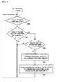
- Fig. 4 is a flowchart showing an operation when the blade server 11a is newly activated.
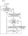
- Figs. 5 through 7 are flowcharts showing operations when the blade server 11 is operated with the local KVM 20.
- Figs. 8 through 10 are flowcharts showing operations when the blade server 11 is operated with the PC 30.
- the operation of the CPU 121 in the KVM device 12 will be focused in the description below.
- the blade server 11a is selected in the description below.
- Reference numerals 11 denotes a general blade server 11
- 112 denotes a general USB microcomputer
- 113 denotes a general switch, in the description below.
- the CPU 121 monitors whether or not any one of the blade servers 11 is newly activated (step S11). This can be determined whether or not a new USB microcomputer 112 has been detected via the interconnection lines 108.
- step S11 If the blade server 11a is detected as a new blade server 11 (Yes in step S11), the CPU 121 emulates the keyboard and the mouse to the activated blade server 11a (step S12). That is, the CPU 121 recreates the state to show the USB microcomputer 112a as if the keyboard and the mouse were connected. Then, the CPU 121 returns to step S11.
- the CPU 121 monitors whether the K signal or the M signal is applied from the keyboard or the mouse, as shown in Fig. 5 (step S21). If the K signal or the M signal is applied (Yes in step S21), the CPU 121 determines whether any one of the blade servers 11 is selected (step S22). The CPU 121 manages the selected blade server 11a with a given memory or the like.
- step S22 if any one of the blade servers 11 is not selected (No in step S22), the CPU 121 returns to the step S21. In the above-mentioned case, the CPU 121 drops the applied K signal or M signal. In contrast, if any one of the blade servers is selected (Yes in step S22), the CPU 121 converts the applied K signal or M signal into the USB format (step S23), and sends the USB format to the USB microcomputer 112a of the selected blade server 11a (step S24). Here, the blade server 11a is selected. Then, the CPU 121 returns to step S21.
- the USB microcomputer 112a inputs the applied K signal or M signal into the K/M signal processing unit 114a. Thus, instructional input information from the keyboard or the mouse is applied to the server structure 111a.
- the CPU 121 monitors whether or not the command is applied to the keyboard or the mouse from any one of the blade servers 11 (step S31). If the command is applied from any one of the blade servers 11 (Yes in step S31), the CPU 121 responds to the blade server 11a that the command has been applied in order to notify that the CPU 121 has received the command (step S32). The CPU 121 judges whether or not the command has come from the selected blade server 11a (step S33). This is determined by the information that is managed in the given memory, as described above.
- step S33 if the command came from the selected blade server 11a (Yes in step S33), the CPU 121 applies the command to the keyboard 21 or the mouse 22 (step S34), and returns to the step S31.
- the keyboard 21 or the mouse 22 executes the process such as a change in setting, according to the applied command.
- the CPU 121 saves the applied command in a given memory temporarily in association with the unselected blade server 11 (step S35), and returns to the step S31.
- the command has come from the blade server 11.
- the CPU 121 monitors whether or not the selected blade server 11 has been changed.
- the selected blade server 11 has changed from 11a to 11b.
- step S41 If the selected blade server 11 has been changed (Yes in step S41), the CPU 121 controls all the USB microcomputers 112 of all the blade servers 11, and turns them off (step S42).
- the control signal to be applied to the OSD processing unit 122 is set to Low (step S42). This prevents the OSD signal from being applied to the monitor 23.
- the CPU 121 determines whether or not there is a blade server that is a newly selected one after change (step S43). If there is a selected blade server 11 (Yes in step S43), the control signal is set to High (step S44). This enables to input the OSD signal applied from the OSD processing unit 122 into the monitor 23. If there is not a selected blade server 11 (No in step S43), the CPU 121 sets the control signal to Low (step S47). This interrupts the input signal applied to the monitor 23.
- step S45 determines whether or not there is the command that has been saved in association with the blade server 11b. This may be performed by reference to the given memory in the step S35 shown in Fig. 6.
- step S45 if there is the stored command (Yes in step S45), the CPU 121 applies the command to the keyboard 21 or the mouse 22 (step S46), and returns to the step S41.
- the keyboard 21 or the mouse 22 performs the process such as a change in setting, based on the applied command. If there is not the stored command (No in step S45), the CPU 121 returns to the step S41.
- the CPU 121 monitors whether or not the IP packet has been received via the LAN 40 (step S51). If the IP packet has been received (Yes in step S51), the CPU 121 further determines whether or not the IP packet includes the K signal or the M signal (step S52). If the received IP packet includes the K signal or the M signal (Yes in step S52), the CPU 121 determines whether or not any one of the blade servers 11 has been selected (step S53). The CPU 121 controls the selected blade server 11 with the given memory.
- step S53 if any one of the blade servers is not selected (No in step S53), the CPU 121 returns to the step S51. In the above-mentioned case, the CPU 121 drops the detected K signal or the M signal. If any one of the blade server has been selected (Yes in step S53.
- the blade server 11a has been selected), the CPU 121 converts the K signal or the M signal into the USB format (step S54), sends the K signal or the M signal in the USB format to the USB microcomputer 112a of the selected blade server 11a (step S55), and then returns to step S51.
- the USB microcomputer 112a applies the inputted K signal or M signal to the K/M signal processing unit 114a.
- the instructional input information of the keyboard or the mouse is given to the server structure 111a.
- the CPU 121 monitors whether or not the command to the keyboard or the mouse has been applied from any one of the blade servers 11 (step S61). If the command has been applied from any one of the blade servers 11 (Yes in step S61), the CPU 121 replies to the blade server 11 in order to notify that the command has been received (step S62). Also, the CPU 121 determines whether or not the command has come from the blade server 11a that is selected by the command (step S63). This is determined by the information managed by the given memory, as described above.
- step S63 if the command has come from the selected blade server 11a (Yes in step S63), the CPU 121 generates the IP packet including the above-mentioned command (step S64), sends the IP packet to the PC 30 (step S65), and returns to step S61.
- the PC 30 that has received the IP packet applies the command included in the IP packet to the keyboard or the mouse connected to the PC 30. If the command has been applied from any one of the unselected blade servers 11 (No in step S63), the CPU 121 temporarily stores the applied in the given memory in association with the blade server 11 from which the command has come (step S66), and returns to the step S61.
- the CPU 121 monitors whether or not the selected blade server has been changed (step S71).
- the selected blade server has been changed from 11a to 11b.
- step S71 If the selected blade server has been changed (Yes in step S71), the CPU 121 controls all the USB microcomputers 112 of all the blade servers 11, and turns off the switch 113 (step S72).
- the control signal to be applied to the OSD processing unit 122 is set to Low. This prevents the OSD signal from being applied to the monitor 23.
- the CPU 121 determines whether or not there is the newly selected blade server (step S73). If there is the newly selected blade server (Yes in step S73), the CPU 121 sets the control signal to High (step S74). Thus, it is possible to input the OSD signal applied from the OSD processing unit 122 into the monitor 23. If there is not the newly selected signal (No in step S78), the CPU 121 sets the control signal to Low (step S78). This prevents the input signal from being applied to the monitor 23.
- the CPU 121 determines whether or not there is the stored command in association with the blade server 11b (step S75). This can be performed by reference to the given memory in step S77 in Fig. 9.
- step S75 if there is the stored command (Yes in step S75), the CPU 121 generates the IP packet including the above-mentioned command (step S76), and sends the IP packet to the PC 30 (step S77).
- the PC 30 that has received the IP packet applies the command included in the IP packet to the keyboard or the mouse connected to the PC 30. If there is not the stored command (No in step S75), the CPU 121 returns to step S71.
- the first embodiment includes the architecture that the KVM device 12 and the blade server 11 are connected by the interface that enables the plug and play.
- the blade server 11a when the blade server 11a is inserted or removed, it is no longer necessary to power off any one of the blade servers 11, the KVM device 12, or the blade chassis 10.
- the KVM device 12 has a chassis structure same as those of the blade servers 11 in accordance with the first embodiment of the present invention. This makes it possible to reduce the number of external cables to connect the KVM device 12 and the blade servers 11 respectively, and also makes it possible to facilitate the system construction and management largely.
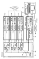
- Fig. 11 is a block diagram showing a blade chassis 10, a blade servers 11a', 11b', and 11c', and a KVM device 12, in accordance with the second embodiment of the present invention. It is to be noted that the present invention is not limited to the three blade servers 11a', 11b', and 11c'.
- USB microcomputers 112a, 112b, and 112c and switches 113a, 113b, and 113c are mounted on a backplane 107' of a blade chassis 10, in accordance with the second embodiment of the present invention.
- the USB microcomputers 112a, 112b, and 112c and the switches 113a, 113b, and 113c are respectively mounted on the blade servers 11a, 11b, and 11c, in accordance with the first embodiment of the present invention.
- Fig. 12 is a block diagram showing a blade chassis 10, a blade servers 11a'', 11b'', and 11c'', and a KVM device 12'', in accordance with the third embodiment of the present invention. It is to be noted that the present invention is not limited to the three blade servers 11a'', 11b'', and 11c''.
- the blade servers 11a'', 11b'', and 11c'' do not include the switch 113a, 113b, or 113c, as compared to the first embodiment of the present invention. Instead, the KVM device 12" is equipped with a control unit 124.
- the control unit 124 is configured to selectively pass the V signal applied from the blade servers 11a'', 11b'', and 11c''. In other words, the control unit 124 passes only the V signal applied from a certain blade server 11 to the OSD processing unit 122. It is to be noted that the user selects the above-mentioned certain blade server 11. Therefore, the control unit 124 applies only the V signal to the OSD processing unit 122, based on the control of the CPU 121. Here, the blade server 11a'' is selected. The operation of the OSD processing unit 122 that the V signal has been applied is the same as that of the OSD processing unit 122 in accordance with the first embodiment of the present invention.
- a local KVM device 20" includes a signal processing unit 24 in accordance with the third embodiment of the present invention.
- the signal processing unit 24 relays or processes the K/M signal and the OSD signal applied from the KVM device 12''.
- the signal processing unit 24 includes a USB microcomputer 25.
- the K/M signal is applied to the USB microcomputer 25 from the keyboard 21 or the mouse 22.
- the USB microcomputer 25 inputs the applied K/M signal into the CPU 121.
- the USB microcomputer 25 may be connected to the CPU 121 with the USB. Also, the keyboard and the mouse may be connected to the USB microcomputer 25 via the USB or another interface such as PS/2.
- the circuits respectively mounted on the blade servers 11a'', 11b'', and 11c'' may be omitted, and thus it is possible to construct the respective blade servers 11a'', 11b'', and 11c'' at a low cost.
- Other components and operation of the above-mentioned architecture in accordance with the third embodiment correspond to those in accordance with the first embodiment of the present invention. Therefore, a detailed explanation will be omitted here.
- Fig. 13 is a block diagram showing a blade chassis 10, blade servers 11a', 11b', and 11c', and a KVM device 12, in accordance with the fourth embodiment of the present invention. It is to be noted that the present invention is not limited to the three blade servers 11a', 11b', and 11c'.
- USB microcomputers 112a, 112b, and 112c are mounted on a backplane 107''' of a blade chassis 10, in accordance with fourth embodiment of the present invention.
- the USB microcomputers 112a, 112b, and 112c are mounted on the blade servers 11a'', 11b'', and 11c'', in accordance with the third embodiment of the present invention.
- the number of circuits respectively mounted on the blade servers 11a', 11b', and 11c' may be reduced, and thus it is possible to construct the respective blade servers 11a', 11b', and 11c' at a relatively low cost.
- Other components and operation of the above-mentioned architecture in accordance with the fourth embodiment of the present invention correspond to those in accordance with the first embodiment of the present invention. Therefore, a detailed explanation is omitted here.
- Fig. 14 is a block diagram showing a blade chassis 10A, blade servers 11a, 11b, and 11c, and a KVM device 12A. It is to be noted that the present invention is not limited to the three blade servers 11a, 11b, and 11c.
- the KVM device 12 is not included in the blade chassis 10A, in accordance with the fifth embodiment of the present invention, although the KVM device 12 is mounted on the blade chassis 10, in accordance with the first embodiment of the present invention.
- the KVM device 12A is connected to interconnection lines 108 in the blade chassis 10A via an external terminal 109 provided on the surface of the blade chassis 10A.
- the structure and operation of the KVM device 12A is same as those of the KVM device 12.
Landscapes
- Engineering & Computer Science (AREA)
- Theoretical Computer Science (AREA)
- Power Engineering (AREA)
- Human Computer Interaction (AREA)
- Physics & Mathematics (AREA)
- General Engineering & Computer Science (AREA)
- General Physics & Mathematics (AREA)
- Computer Hardware Design (AREA)
- Power Sources (AREA)
- Multi Processors (AREA)
Abstract
Description
- This invention generally relates to a server system and a signal processing unit, a server, and a chassis thereof that enable to operate at least one server with a set of console.
- A conventional technique for directly accessing a server on a network by remote control has been proposed in Japanese Patent Application Publication No. 2001-344189. Fig. 1 shows an example of a remote control system with the use of the above-mentioned conventional technique.
- The system architecture shown in Fig. 1 includes multiple groups of
servers 910. Each group is composed of a chassis on which multiple servers 911 are mounted. The servers 911 are connected to aserver switching unit 901 via connectors for outputting display images such as VGA (Video Graphics Array) connector, keyboard connector, mouse connector such as PS/2® connector, or the like. - The
server switching unit 901 is connected to anetwork 903 such as a LAN (Local Area Network), the Internet, or the like. By way of thenetwork 903, theserver switching unit 901 is configured to communicate with aninformation processing device 920 such as a personal computer (hereinafter simply referred to as PC), a workstation, or the like. - More specifically, the
server switching unit 901, upon request of theinformation processing device 920, selectively connects theinformation processing device 920 to the requested server 911. In the above-mentioned case, theserver switching unit 901 generates, for example, an IP (Internet Protocol) packet based on a displayed image outputted from the VGA connector of the server 911, and sends the IP packet to theinformation processing device 920. Theinformation processing device 920 receives the IP packet from thenetwork 903 based on an IP address, and displays the image displayed on the server 911 on amonitor 921. Theinformation processing device 920 also converts instructional information inputted with a keyboard or mouse in response to the above-mentioned displayed image into an IP packet, and sends the IP packet to theserver switching unit 901. Theserver switching unit 901 receives the IP packet including the instructional information from thenetwork 903 based on the IP address, extracts the instructional information, and outputs the instructional information to the keyboard connector or the mouse connector of the server 911. - The
server switching unit 901 makes theinformation processing unit 920 serve as an input/output device for the monitor, keyboard, mouse or the like connected to a selected server 911. This allows the operator to operate the above-mentioned input/output device as if the input/output device were directly connected to the server 911. - Conventionally, the servers 911 are respectively connected to the
network 903, in addition to being respectively connected to theserver switching unit 901. That is, the servers 911 are equipped with network adapters. - Besides, with the above-mentioned architecture, additional cables are required for respectively connecting the servers 911 to the
server switching unit 901 and for respectively connecting the servers 911 to thenetwork 903. Therefore, more cables are required as the number of the servers 911 grows. Particularly, in recent years, the mainstream architecture of large-scale systems is that multiple servers 911 are mounted on a single chassis (the group ofservers 910 shown in Fig. 1). With the above-mentioned architecture, it is to be noted that a large number of connecting cables are aggregated in one place, which causes troublesome situations to lay and manage the cables. - Further, in the case where a server 911 is newly added, it is necessary to power off all the other servers 911 mounted on the chassis to which the server 911 is newly added. Thus, there is the problem in that a system cannot flexibly be altered.
- It is therefore an object of the present invention to provide a server system, a signal processing unit, a server, and a chassis thereof that enable to facilitate system construction, system alteration, and system management.
- According to an aspect of the present invention, there is provided a server system including at least one server, a signal processing unit that enables to operate said at least one server with a set of console, and a chassis having slots and a circuit board, said at least one server or the signal processing unit being attachable and detachable to any of the slots, the circuit board having interconnection lines connecting the slots, said at least one server and the signal processing unit being connected via an interface that allows plug and play connectivity.
- According to another aspect of the present invention, there is provided a signal processing unit including a first circuit having an interface that allows plug and play connectivity, and a second circuit connectable to a server system via the first circuit, the server system having slots that are provided to a chassis and are connected together via interconnection lines, a server being any of the slots.
- According to yet another aspect of the present invention, there is provided a server including a connector that allows the server to be inserted into any of slots that are provided to a chassis of a server system and are mutually connected via interconnection lines, and an interface circuit connected to a signal processing unit that is inserted into one of the slots and has an interface that allows the server to be connected to the signal processing unit with plug and play connectivity.
- According to further another aspect of the present invention, there is provided a chassis including a circuit board having slots into which servers can be inserted, and interconnection lines that are provided to the circuit board and connects the slots, the servers being connected, via the interconnection lines, to a signal processing unit having an interface that enables to operate the servers with a single set of console.
- Other objects, features and advantages of the present invention will become more apparent from the following detailed description when read in conjunction with the accompanying drawings, in which:
- Fig. 1 shows an example of a remote control system with the use of a conventional technique;
- Fig. 2 shows architecture of a
server system 1 in accordance with a first embodiment of the present invention; - Fig. 3 is a block diagram showing structures of a
blade chassis 10, ablade server 11, and aKVM device 12 in accordance with the first embodiment of the present invention; - Fig. 4 is a flowchart showing operations when the
blade server 11a is newly activated in accordance with the first embodiment of the present invention; - Fig. 5 is a flowchart showing operations when the
blade server 11 is operated with the local KVM 20 (1) in accordance with the first embodiment of the present invention; - Fig. 6 is a flowchart showing operations when the
blade server 11 is operated with the local KVM 20 (2) in accordance with the first embodiment of the present invention; - Fig. 7 is a flowchart showing operations when the
blade server 11 is operated with the local KVM 20 (3) in accordance with the first embodiment of the present invention; - Fig. 8 is a flowchart showing operations when the
blade server 11 is operated with the PC 30 (1) in accordance with the first embodiment of the present invention; - Fig. 9 is a flowchart showing operations when the
blade server 11 is operated with the PC 30 (2) in accordance with the first embodiment of the present invention; - Fig. 10 is a flowchart showing operations when
the
blade server 11 is operated with the PC 30 (3) in accordance with the first embodiment of the present invention; - Fig. 11 is a block diagram showing architecture
of a
blade chassis 10, ablade servers 11a', 11b', and 11c', and aKVM device 12, in accordance with a second embodiment of the present invention; - Fig. 12 is a block diagram showing architecture
of a
blade chassis 10, ablade servers 11a'', 11b'', and 11c'', and a KVM device 12'', in accordance with the third embodiment of the present invention; - Fig. 13 is a block diagram showing architecture
of a
blade chassis 10,blade servers 11a', 11b', and 11c', and aKVM device 12, in accordance with a fourth embodiment of the present invention; and - Fig. 14 is a block diagram showing architecture
of a
blade chassis 10A,blade servers KVM device 12A in accordance with a fifth embodiment of the present invention. -
- A description will now be given of embodiments of the present invention with reference to the accompanying drawings.
- A first embodiment of the present invention will be first described in detail, with reference to the accompanying drawings. Fig. 2 shows architecture of a
server system 1. - Referring to Fig. 2, the
server system 1 includes at least oneblade chassis 10 having at least oneblade server 11. Theblade server 11 includes a network adapter, as will be described later in detail, and a jack on the font side or back side thereof so that a LAN cable or the like may be connected to. Theblade server 11 is connected to aLAN 40 via the above-mentioned LAN cable. However, not limited to theLAN 40, theblade server 11 may be connected to various types of networks such as a WAN (Wide Area Network) or the Internet. - The
LAN 40 includes, for example, a HUB 41 that serves as a relay node. The HUB 41 propagates IP packets that are communicated among connected servers and clients. APC 30 is connected to theLAN 40 as a client terminal, in accordance with the first embodiment of the present invention. - The
blade chassis 10, which will be described later in detail, includesslots blade server 11 and a KVM (Keyboard-Video-Mouse)device 12 may be respectively inserted. Theblade chassis 10 also includes a circuit board (a backplane 107) havinginterconnection lines 108 that respectively connect theblade servers 11 and theKVM device 12. As described above, theKVM device 12 may be inserted into and removed from theblade chassis 10 on which theblade servers 11 are mounted. Therefore, theinterconnection lines 108, which connect theblade servers 11 and theKVM device 12, may also be mounted on theblade chassis 10. This makes it possible to readily connect theblade servers 11 and theKVM device 12 without an external cable or the like. - The
KVM device 12 is a signal processing unit that connects an input/output device and a display device to any one of theblade servers 11. The input/output device denotes a keyboard or a mouse. The display device denotes a monitor. TheKVM device 12, as will be described later in detail, is connected to at least oneblade server 11 via abackplane 107 on theblade chassis 10. TheKVM 12 is capable of locally connecting alocal KVM 20 having akeyboard 21, amouse 22, and amonitor 23. "K" for KVM denotes keyboard, "V" denotes monitor, and "M" denotes mouse. Thelocal KVM 20 is a set of console that is used for operating theblade servers 11. - The basic operation of the
KVM device 12 will be described. TheKVM device 12 inputs data applied from thekeyboard 21 or themouse 22, into theblade server 11. The data includes, for example, a keyboard signal (hereinafter simply referred to as K signal) or a mouse signal (hereinafter simply referred to as M signal). The K signal is generated by thekeyboard 21 based on a user's manipulation. The M signal is generated by themouse 22 based on the user's manipulation. Also, theKVM device 12 applies data that is outputted from theblade server 11 to thekeyboard 21, themouse 22, or themonitor 23. The data includes a command that theblade server 11 gives instructions to thekeyboard 21 or themouse 22 and a video signal (hereinafter simply referred to as V signal) that theblade server 11 displays on an output screen such as a console screen or a GUI (graphical User Interface) screen. - The
KVM device 12 controls input and output of various types of data based on the request from a user. TheKVM device 12 inputs the data from thekeyboard 21 or themouse 22 into any one of theblade servers 11 that is selected by the user. Also, theKVM device 12 inputs the data from any one of theblade servers 11 that the user selects, into thekeyboard 21, themouse 22, or themonitor 23. Thus, with theKVM 12, it is possible to realize a computing environment as if thekeyboard 21, themouse 22, and themonitor 23 were directly connecting to the selectedblade server 11. - In addition to the above-mentioned configuration, another KVM device that is provided with the
PC 30 to manipulate theblade server 11 as a set of console, in accordance with the first embodiment of the present invention. That is, the user is able to operate theblade server 11 with thePC 30, in accordance with the first embodiment of the present invention. In order to achieve this, theKVM device 12 is equipped with a network adapter, as will be described later in detail, and a jack on the front or back side thereof so as to connect a LAN cable or the like. With theKVM device 12, it is also possible to realize another computing environment that the selectedblade server 11 may be operated with thePC 30 by sending and receiving data to and from thePC 30 via theLAN 40. - A description will be given of the
blade chassis 10, theblade server 11, and theKVM device 12 in accordance with the first embodiment, with reference to the accompanying drawings. - Fig. 3 is a block diagram showing structures of the
blade chassis 10, theblade server 11, and theKVM device 12. In the description below, theblade chassis 10 includes three blade servers, 11a, 11b, and 11c. - The
blade server 11a includes a circuit board on which aserver structure 111a, a USB (Universal Serial Bus)microcomputer 112a, a switch (SW) 113a are mounted. Theserver structure 111a, theUSB microcomputer 112a, and theswitch 113a are interconnected via a bus provided on the circuit board.Other blade servers blade server 11a will be described below. - First, a description will be given of the
server structure 111a. Theserver structure 111a includes a K/Msignal processing unit 114a, a Vsignal processing unit 115a, and anetwork adapter 116a, in addition to a CPU (Central Processing Unit), a memory, and a hard disc. Aforementioned components are included in a general server. - The
network adapter 116a is used for connecting theserver structure 111a independently to theLAN 40. Thenetwork adapter 116a is equipped with a jack into which a LAN cable is plugged. - The K/M
signal processing unit 114a processes inputted K signal or M signal as instructional information from the user, and outputs the instructional information into the CPU in theserver structure 111a. The K signal or the M signal (hereinafter referred to as K/M signal) is inputted into the K/Msignal processing unit 114a from theKVM device 12 via theUSB microcomputer 112a. - The K/M
signal processing unit 114a outputs a command for setting up the keyboard or mouse. This command may be generated by the K/Msignal processing unit 114a or another component of theserver structure 111a such as theCPU 121. The command outputted from the K/Msignal processing unit 114a is inputted into theKVM device 12 via theUSB microcomputer 112a. TheKVM device 12 outputs the inputted command into the keyboard or mouse as necessary, or sends the command to thePC 30 that is connected via theLAN 40. - The V
signal processing unit 115a outputs an output screen of theblade server 11a as a V signal of RGB (Red/Green/Blue) method or DVI (Digital Visual Interface) method. The RGB method may employ analogue or digital method. The RGB method will be described below. The Vsignal processing unit 115a outputs both horizontal and vertical synchronizing signals. Therefore, in the description below, the above-mentioned signals will be included in the V signal. The V signal outputted from the Vsignal processing unit 115a is applied to theKVM device 12 via theswitch 113a. TheKVM device 12 generates an image of the output screen, based on the applied V signal, and displays the image as necessary or as required or sends to thePC 30 connected via theLAN 40. This image is displayed on themonitor 23 or amonitor 31 as OSD (On Screen Display). - Next, a description will be given of other components. The
USB microcomputer 112a incorporates a USB interface circuit that allows plug and play connectivity, and controls an interface that connects theblade server 11a and theKVM device 12. Theblade server 11a and theKVM device 12 are thus connected with the interface that enables plug and play connectivity such as the above-mentioned USB interface. Therefore, it is no longer necessary to power off other blade servers, theKVM device 12, or theblade chassis 10 when theblade server 11a is inserted or removed. In addition, the interface that allows plug and play connectivity is readily able to control the situation when theblade server 11 is newly activated. Further, it is possible to switch from any one of theblade servers 11 to another one immediately, by employing the interface that allows plug and play connectivity. TheUSB microcomputer 112a may be replaced by another microcomputer that incorporates another bus interface circuit, if the interface enables plug and play connectivity. - The
USB microcomputer 112a inputs the K/M signal into the K/Msignal processing unit 114a as necessary, The K/M signal is applied from theKVM device 12. In addition, theUSB microcomputer 112a applies the command that is inputted from the K/Msignal processing unit 114a into theKVM device 12 as necessary or as required. Therefore, the respective blade servers are required to include theUSB microcomputers - Further, the
USB microcomputer 112a controls theswitch 113a by turning on and off, based upon the control from theCPU 121. Theswitch 113a is configured to enable or disenable the output of the V signal and selectively pass the V signal applied from aspecific blade server 11. Thus, theswitch 113a may be composed of a simple on/off switch. TheUSB microcomputer 112a selectively changes the status of the selected signal, High or Low, which is to be applied to a control terminal of theswitch 113a. In the description below, in the case where the selected signal is High, theswitch 113a turns on and passes the V signal applied from the Vsignal processing unit 115a. In the case where the selected signal is Low, theswitch 113a turns off and interrupts the V signal. - The above-mentioned
blade servers slots 105 that are provided on theblade chassis 10. Theblade chassis 10 includes abackplane 107. Thebackplane 107 is equipped with signal lines, which are theinterconnection lines 108 to connect therespective blade servers 11. Thebackplane 107 is also equipped with a power supply line for providing therespective blade servers 11 and theKVM device 12 with a power supply circuit and power. Thebackplane 107 is also provided with sockets into which connectors of theblade servers blade servers blade chassis 10. Card edge connectors, for example, may be employed for the connectors on theblade servers - The
USB microcomputer 11a and theswitch 113a are connected to theinterconnection lines 108, by inserting theblade server 11a into theblade chassis 10. Other bus or power supply lines are also connected to given lines of thebackplane 107. The interconnection lines 108 are composed of two lines for USB connection and five lines for RGB connection. The lines are respectively branched and connected to the sockets provided on theslots 105 of theblade chassis 10. - The
KVM device 12 includes aCPU 121, anOSD processing unit 122, and anetwork adapter 123 mounted on a single circuit board. TheCPU 121, theOSD processing unit 122, and thenetwork adapter 123 are interconnected via the bus provided on the circuit board. - The
KVM device 12 having the above-mentioned structure is inserted into theslot 106 provided on theblade chassis 10. Theslot 106 may have the same shape as those of theslots 105 for theblade servers KVM device 12 may be produced with the same circuit board as that of theblade server 10. When theKVM device 12 is inserted into theslot 106, the connectors of theKVM device 12 are plugged into the sockets of thebackplane 107. This is same as the case where theblade servers slots 105. Thus, theCPU 121 and theOSD processing unit 122 are connected together on the interconnection lines 108. TheKVM device 12 may be inserted into any slot, if the connector of theKVM device 12 is designed to have the same shape as those of theblade servers - The
CPU 121 is connected to theUSB microcomputers interconnection lines 108 to input and output the K/M signal and the commands into theUSB microcomputers CPU 121 outputs the K/M signal applied from thelocal KVM 20 into the USB microcomputer of the blade server that is selected by the user. In the description below, theblade server 11a is selected. In addition, theCPU 121 inputs the command applied from the selectedblade server 11a to thekeyboard 21 or themouse 22. Further, theCPU 121 temporarily saves the command applied from unselected blade servers in a given memory such as a cache memory. Here, the unselected blade servers are theblade servers blade servers keyboard 21 or themouse 22. TheCPU 121 may be connected to thekeyboard 21 and themouse 22 via the USB or another interface such as PS/2 or the like. - The
CPU 121 turns on theswitch 113a, by controlling theUSB microcomputer 112a of the selectedblade server 11a. Simultaneously, theCPU 121 turns off theswitches USB microcomputers blade servers CPU 121 controls theUSB microcomputers blade server 11a. - Further, if any one of the blade servers is not selected, the
CPU 121 stops the operation of theOSD processing unit 122, by setting the control signal to Low, for example. The Low control signal turns off theOSD processing unit 122, and disconnects the signals to thenetwork adapter 123. In contrast, if any one of the blade servers is selected, theCPU 121 starts the operation of theOSD processing unit 122, by setting the control signal to High, for example. The High control signal turns on theOSD processing unit 122, and applies an OSD signal or the like to thenetwork adapter 123. The OSD signal will be described later in detail. - Here, the operation of the
OSD processing unit 122 will be described. TheOSD processing unit 122 generates an image of the output screen to be displayed on themonitor 23, based on the applied V signal. This image is generated as image data in bitmap format, GIF (Graphical Interchange Format) format, JPEG (Joint Photographic Experts Group) format, or the like. - In the case where the
local KVM 20 is operated, theOSD processing unit 122 generates the OSD signal from the generated image, and applies the OSD signal to thenetwork adapter 123. Thenetwork adapter 123 outputs the applied OSD signal into themonitor 23. Thenetwork adapter 123 and themonitor 23 may be connected via an interface for connecting a display such as RGB cable or DVI method. Another type of interface such as RS-232c may be employed. - In the case where the
PC 30 is operated, theOSD processing unit 122 applies the generated image to thenetwork adapter 123 without change. Thenetwork adapter 123 generates an IP packet based on the applied image, and sends the IP packet to thePC 30 via theLAN 40. ThePC 30 displays the image that is obtained from the received IP packet, in a pop-up window on themonitor 31. - In the case where the blade server is operated with the
local KVM 20, the user operates thekeyboard 21 in a given manner. Thus generated K signal is applied to theCPU 121. TheCPU 121 detects the applied K signal and determines that thelocal KVM 20 has been operated. In contrast, in the case where the blade server is operated with thePC 30, the user accesses theKVM device 12, based on an IP address assigned to thenetwork adapter 123 of theKVM device 12, and inputs a given command. The inputted given command is applied to theCPU 121. TheCPU 121 determines that thePC 30 has been operated, with the applied given command. - Next, a description will be given of the operation of the
server system 1 with the accompanying drawings, in accordance with the first embodiment of the present invention. Fig. 4 is a flowchart showing an operation when theblade server 11a is newly activated. Figs. 5 through 7 are flowcharts showing operations when theblade server 11 is operated with thelocal KVM 20. Figs. 8 through 10 are flowcharts showing operations when theblade server 11 is operated with thePC 30. The operation of theCPU 121 in theKVM device 12 will be focused in the description below. Also, theblade server 11a is selected in the description below.Reference numerals 11 denotes ageneral blade server 11, 112 denotes a general USB microcomputer, and 113 denotes a general switch, in the description below. - Referring to Fig. 4, the
CPU 121 monitors whether or not any one of theblade servers 11 is newly activated (step S11). This can be determined whether or not a new USB microcomputer 112 has been detected via the interconnection lines 108. - If the
blade server 11a is detected as a new blade server 11 (Yes in step S11), theCPU 121 emulates the keyboard and the mouse to the activatedblade server 11a (step S12). That is, theCPU 121 recreates the state to show theUSB microcomputer 112a as if the keyboard and the mouse were connected. Then, theCPU 121 returns to step S11. - Here, if the
blade server 11 is operated with thelocal KVM 20, theCPU 121 monitors whether the K signal or the M signal is applied from the keyboard or the mouse, as shown in Fig. 5 (step S21). If the K signal or the M signal is applied (Yes in step S21), theCPU 121 determines whether any one of theblade servers 11 is selected (step S22). TheCPU 121 manages the selectedblade server 11a with a given memory or the like. - In step S22, if any one of the
blade servers 11 is not selected (No in step S22), theCPU 121 returns to the step S21. In the above-mentioned case, theCPU 121 drops the applied K signal or M signal. In contrast, if any one of the blade servers is selected (Yes in step S22), theCPU 121 converts the applied K signal or M signal into the USB format (step S23), and sends the USB format to theUSB microcomputer 112a of the selectedblade server 11a (step S24). Here, theblade server 11a is selected. Then, theCPU 121 returns to step S21. TheUSB microcomputer 112a inputs the applied K signal or M signal into the K/Msignal processing unit 114a. Thus, instructional input information from the keyboard or the mouse is applied to theserver structure 111a. - The
CPU 121 monitors whether or not the command is applied to the keyboard or the mouse from any one of the blade servers 11 (step S31). If the command is applied from any one of the blade servers 11 (Yes in step S31), theCPU 121 responds to theblade server 11a that the command has been applied in order to notify that theCPU 121 has received the command (step S32). TheCPU 121 judges whether or not the command has come from the selectedblade server 11a (step S33). This is determined by the information that is managed in the given memory, as described above. - As a result of the decision of the step S33, if the command came from the selected
blade server 11a (Yes in step S33), theCPU 121 applies the command to thekeyboard 21 or the mouse 22 (step S34), and returns to the step S31. Thekeyboard 21 or themouse 22 executes the process such as a change in setting, according to the applied command. In contrast, if the command came from any one of the unselected blade servers 11 (No in step S33), theCPU 121 saves the applied command in a given memory temporarily in association with the unselected blade server 11 (step S35), and returns to the step S31. The command has come from theblade server 11. - Referring to Fig. 7, the
CPU 121 monitors whether or not the selectedblade server 11 has been changed. Here, a description will be given of the case where the selectedblade server 11 has changed from 11a to 11b. - If the selected
blade server 11 has been changed (Yes in step S41), theCPU 121 controls all the USB microcomputers 112 of all theblade servers 11, and turns them off (step S42). The control signal to be applied to theOSD processing unit 122 is set to Low (step S42). This prevents the OSD signal from being applied to themonitor 23. - Then, the
CPU 121 determines whether or not there is a blade server that is a newly selected one after change (step S43). If there is a selected blade server 11 (Yes in step S43), the control signal is set to High (step S44). This enables to input the OSD signal applied from theOSD processing unit 122 into themonitor 23. If there is not a selected blade server 11 (No in step S43), theCPU 121 sets the control signal to Low (step S47). This interrupts the input signal applied to themonitor 23. - If the selected
blade server 11a has been changed to theblade server 11b, theCPU 121 determines whether or not there is the command that has been saved in association with theblade server 11b (step S45). This may be performed by reference to the given memory in the step S35 shown in Fig. 6. - As a result of the step S45, if there is the stored command (Yes in step S45), the
CPU 121 applies the command to thekeyboard 21 or the mouse 22 (step S46), and returns to the step S41. Thekeyboard 21 or themouse 22 performs the process such as a change in setting, based on the applied command. If there is not the stored command (No in step S45), theCPU 121 returns to the step S41. - Thus, it is possible to operate a desired
blade server 11 with thelocal KVM 20. - Referring to Fig. 8, in the case where the
blade server 11 is operated with thePC 30, theCPU 121 monitors whether or not the IP packet has been received via the LAN 40 (step S51). If the IP packet has been received (Yes in step S51), theCPU 121 further determines whether or not the IP packet includes the K signal or the M signal (step S52). If the received IP packet includes the K signal or the M signal (Yes in step S52), theCPU 121 determines whether or not any one of theblade servers 11 has been selected (step S53). TheCPU 121 controls the selectedblade server 11 with the given memory. - As a result of the step S53, if any one of the blade servers is not selected (No in step S53), the
CPU 121 returns to the step S51. In the above-mentioned case, theCPU 121 drops the detected K signal or the M signal. If any one of the blade server has been selected (Yes in step S53. Theblade server 11a has been selected), theCPU 121 converts the K signal or the M signal into the USB format (step S54), sends the K signal or the M signal in the USB format to theUSB microcomputer 112a of the selectedblade server 11a (step S55), and then returns to step S51. TheUSB microcomputer 112a applies the inputted K signal or M signal to the K/Msignal processing unit 114a. Thus, the instructional input information of the keyboard or the mouse is given to theserver structure 111a. - Referring to Fig. 9, the
CPU 121 monitors whether or not the command to the keyboard or the mouse has been applied from any one of the blade servers 11 (step S61). If the command has been applied from any one of the blade servers 11 (Yes in step S61), theCPU 121 replies to theblade server 11 in order to notify that the command has been received (step S62). Also, theCPU 121 determines whether or not the command has come from theblade server 11a that is selected by the command (step S63). This is determined by the information managed by the given memory, as described above. - As a result of step S63, if the command has come from the selected
blade server 11a (Yes in step S63), theCPU 121 generates the IP packet including the above-mentioned command (step S64), sends the IP packet to the PC 30 (step S65), and returns to step S61. ThePC 30 that has received the IP packet applies the command included in the IP packet to the keyboard or the mouse connected to thePC 30. If the command has been applied from any one of the unselected blade servers 11 (No in step S63), theCPU 121 temporarily stores the applied in the given memory in association with theblade server 11 from which the command has come (step S66), and returns to the step S61. - Referring to Fig. 10, the
CPU 121 monitors whether or not the selected blade server has been changed (step S71). Here, a description will be given of the case where the selected blade server has been changed from 11a to 11b. - If the selected blade server has been changed (Yes in step S71), the
CPU 121 controls all the USB microcomputers 112 of all theblade servers 11, and turns off the switch 113 (step S72). In the above-mentioned case, the control signal to be applied to theOSD processing unit 122 is set to Low. This prevents the OSD signal from being applied to themonitor 23. - Then, the
CPU 121 determines whether or not there is the newly selected blade server (step S73). If there is the newly selected blade server (Yes in step S73), theCPU 121 sets the control signal to High (step S74). Thus, it is possible to input the OSD signal applied from theOSD processing unit 122 into themonitor 23. If there is not the newly selected signal (No in step S78), theCPU 121 sets the control signal to Low (step S78). This prevents the input signal from being applied to themonitor 23. - If the selected
blade server 11 has been changed, theCPU 121 determines whether or not there is the stored command in association with theblade server 11b (step S75). This can be performed by reference to the given memory in step S77 in Fig. 9. - As a result of step S75, if there is the stored command (Yes in step S75), the
CPU 121 generates the IP packet including the above-mentioned command (step S76), and sends the IP packet to the PC 30 (step S77). ThePC 30 that has received the IP packet applies the command included in the IP packet to the keyboard or the mouse connected to thePC 30. If there is not the stored command (No in step S75), theCPU 121 returns to step S71. - Thus, it is possible to operate a desired
blade server 11 with thePC 30. - As described above, the first embodiment includes the architecture that the
KVM device 12 and theblade server 11 are connected by the interface that enables the plug and play. Thus, when theblade server 11a is inserted or removed, it is no longer necessary to power off any one of theblade servers 11, theKVM device 12, or theblade chassis 10. In addition, with the above-mentioned architecture, it is readily connect theCPU 121 and theUSB microcomputer 112a. Further, it is possible to change the selected blade server immediately. In addition to the above-mentioned technical merits, theKVM device 12 has a chassis structure same as those of theblade servers 11 in accordance with the first embodiment of the present invention. This makes it possible to reduce the number of external cables to connect theKVM device 12 and theblade servers 11 respectively, and also makes it possible to facilitate the system construction and management largely. - Next, a description will now be given of a second embodiment of the present invention, with reference to the accompanying drawings. Hereinafter, in the second embodiment, the same components and configurations as those of the first embodiment have the same reference numerals and a detailed explanation will be omitted, if not otherwise specified.
- Fig. 11 is a block diagram showing a
blade chassis 10, ablade servers 11a', 11b', and 11c', and aKVM device 12, in accordance with the second embodiment of the present invention. It is to be noted that the present invention is not limited to the threeblade servers 11a', 11b', and 11c'. - Referring to Fig. 11,
USB microcomputers switches blade chassis 10, in accordance with the second embodiment of the present invention. In contrast, theUSB microcomputers switches blade servers - With the above-mentioned architecture, it is possible to reduce the circuits that should be mounted on the
respective blade servers 11a', 11b', and 11c', and it is thus possible to constructrespective blade servers 11a', 11b', and 11c' at a relatively low cost. Other components and operation of the above-mentioned architecture in accordance with the second embodiment of the present invention correspond to those in accordance with the first embodiment of the present invention. Therefore, a detailed explanation is omitted here. - Next, a description will be given of a third embodiment of the present invention, with reference to the accompanying drawings. Hereinafter, in the third embodiment, the same components and configurations as those of the first and second embodiments have the same reference numerals and a detailed explanation will be omitted, if not otherwise specified.
- Fig. 12 is a block diagram showing a
blade chassis 10, ablade servers 11a'', 11b'', and 11c'', and a KVM device 12'', in accordance with the third embodiment of the present invention. It is to be noted that the present invention is not limited to the threeblade servers 11a'', 11b'', and 11c''. - Referring to Fig. 12, the
blade servers 11a'', 11b'', and 11c'' do not include theswitch KVM device 12" is equipped with acontrol unit 124. - The
control unit 124 is configured to selectively pass the V signal applied from theblade servers 11a'', 11b'', and 11c''. In other words, thecontrol unit 124 passes only the V signal applied from acertain blade server 11 to theOSD processing unit 122. It is to be noted that the user selects the above-mentionedcertain blade server 11. Therefore, thecontrol unit 124 applies only the V signal to theOSD processing unit 122, based on the control of theCPU 121. Here, theblade server 11a'' is selected. The operation of theOSD processing unit 122 that the V signal has been applied is the same as that of theOSD processing unit 122 in accordance with the first embodiment of the present invention. - A
local KVM device 20" includes asignal processing unit 24 in accordance with the third embodiment of the present invention. Thesignal processing unit 24 relays or processes the K/M signal and the OSD signal applied from the KVM device 12''. Thesignal processing unit 24 includes aUSB microcomputer 25. The K/M signal is applied to theUSB microcomputer 25 from thekeyboard 21 or themouse 22. TheUSB microcomputer 25 inputs the applied K/M signal into theCPU 121. TheUSB microcomputer 25 may be connected to theCPU 121 with the USB. Also, the keyboard and the mouse may be connected to theUSB microcomputer 25 via the USB or another interface such as PS/2. - With the above-mentioned architecture, the circuits respectively mounted on the
blade servers 11a'', 11b'', and 11c'' may be omitted, and thus it is possible to construct therespective blade servers 11a'', 11b'', and 11c'' at a low cost. Other components and operation of the above-mentioned architecture in accordance with the third embodiment correspond to those in accordance with the first embodiment of the present invention. Therefore, a detailed explanation will be omitted here. - Next, a description will be given of a fourth embodiment of the present invention, with reference to the accompanying drawings. Hereinafter, in the fourth embodiment, the same components and configurations as those of the first through third embodiments have the same reference numerals and a detailed explanation will be omitted, if not otherwise specified.
- Fig. 13 is a block diagram showing a
blade chassis 10,blade servers 11a', 11b', and 11c', and aKVM device 12, in accordance with the fourth embodiment of the present invention. It is to be noted that the present invention is not limited to the threeblade servers 11a', 11b', and 11c'. - Referring to Fig. 13,
USB microcomputers blade chassis 10, in accordance with fourth embodiment of the present invention. In contrast, theUSB microcomputers blade servers 11a'', 11b'', and 11c'', in accordance with the third embodiment of the present invention. - With the above-mentioned architecture, the number of circuits respectively mounted on the
blade servers 11a', 11b', and 11c' may be reduced, and thus it is possible to construct therespective blade servers 11a', 11b', and 11c' at a relatively low cost. Other components and operation of the above-mentioned architecture in accordance with the fourth embodiment of the present invention correspond to those in accordance with the first embodiment of the present invention. Therefore, a detailed explanation is omitted here. - Next, a description will be given of a fifth embodiment of the present invention, with reference to the accompanying drawings. Hereinafter, in the fifth embodiment, the same components and configurations as those of the first through fourth embodiments have the same reference numerals and a detailed explanation will be omitted, if not otherwise specified.
- Fig. 14 is a block diagram showing a
blade chassis 10A,blade servers KVM device 12A. It is to be noted that the present invention is not limited to the threeblade servers - Referring to Fig. 14, the
KVM device 12 is not included in theblade chassis 10A, in accordance with the fifth embodiment of the present invention, although theKVM device 12 is mounted on theblade chassis 10, in accordance with the first embodiment of the present invention. TheKVM device 12A is connected tointerconnection lines 108 in theblade chassis 10A via anexternal terminal 109 provided on the surface of theblade chassis 10A. The structure and operation of theKVM device 12A is same as those of theKVM device 12. - With the above-mentioned architecture, it is possible to prevent the
blade chassis 10 from getting bigger, and it is also possible to prevent the number of theblade servers 11 from decreasing. Other components and operation of the above-mentioned architecture in accordance with the fifth embodiment of the present invention correspond to those in accordance with the first embodiment of the present invention. Therefore, a detailed explanation is omitted here. - Although a few preferred embodiments of the present invention have been shown and described, it would be appreciated by those skilled in the art that changes may be made in these embodiments without departing from the principles and spirit of the invention, the scope of which is defined in the claims and their equivalents.
- The entire disclosure of Japanese Patent Application No. 2003-385198 filed on November 14, 2003 including specification, claims, drawings, and abstract is incorporated herein by reference in its entirety.
Claims (14)
- A server system comprising:at least one server;a signal processing unit that enables to operate said at least one server with a set of console; anda chassis having slots and a circuit board, said at least one server or the signal processing unit being attachable and detachable to any of the slots, the circuit board having interconnection lines connecting the slots,said at least one server and the signal processing unit being connected via an interface that allows plug and play connectivity.
- A signal processing unit comprising:a first circuit having an interface that allows plug and play connectivity; anda second circuit connectable to a server system via the first circuit, the server system having slots that are provided to a chassis and are connected together via interconnection lines, a server being any of the slots.
- The signal processing unit as claimed in claim 2, wherein the signal processing unit is attachable to any one of the slots of the server system.
- The signal processing unit as claimed in claim 2, comprising a control circuit that passes only video signals applied from any one of servers inserted into the slots.
- The signal processing unit as claimed in claim 2, comprising a network adapter that sends and receives packets to and from a client terminal via a network,
the servers inserted into the slots being operated with the set of console provided in the client terminal. - A server comprising:a connector that allows the server to be inserted into any of slots that are provided to a chassis of a server system and are mutually connected via interconnection lines; andan interface circuit connected to a signal processing unit that is inserted into one of the slots and has an interface that allows the server to be connected to the signal processing unit with plug and play connectivity.
- The server as claimed in claim 6, further comprising a microcomputer that controls the interface.
- The server as claimed in claim 6, further comprising a switch that enables or disables an output of video signals.
- A chassis comprising:a circuit board having slots into which servers can be inserted; andinterconnection lines that are provided to the circuit board and connects the slots,the servers being connected, via the interconnection lines, to a signal processing unit having an interface that enables to operate the servers with a single set of console.
- The chassis as claimed in claim 9, wherein the slots can accommodate the signal processing unit.
- The chassis as claimed in claim 9, further comprising an external terminal that connects the signal processing unit to the interconnection lines.
- The chassis as claimed in claim 9, further comprising a microcomputer that controls the interface that has the plug and play connectivity.
- The chassis as claimed in claim 9, further comprising switches that are provided to slots and enable or disable video signals applied from the servers.
- The chassis as claimed in claim 9, wherein the circuit board includes a control circuit that passes only a video signal applied from any one of the servers.
Applications Claiming Priority (2)
| Application Number | Priority Date | Filing Date | Title |
|---|---|---|---|
| JP2003385198 | 2003-11-14 | ||
| JP2003385198A JP4490077B2 (en) | 2003-11-14 | 2003-11-14 | Server system, signal processing apparatus thereof, server thereof, and casing thereof |
Publications (3)
| Publication Number | Publication Date |
|---|---|
| EP1533680A2 true EP1533680A2 (en) | 2005-05-25 |
| EP1533680A3 EP1533680A3 (en) | 2006-12-20 |
| EP1533680B1 EP1533680B1 (en) | 2013-01-09 |
Family
ID=34431499
Family Applications (1)
| Application Number | Title | Priority Date | Filing Date |
|---|---|---|---|
| EP04257033A Expired - Lifetime EP1533680B1 (en) | 2003-11-14 | 2004-11-12 | Server system and signal processing unit, server, and chassis thereof |
Country Status (3)
| Country | Link |
|---|---|
| US (1) | US7590786B2 (en) |
| EP (1) | EP1533680B1 (en) |
| JP (1) | JP4490077B2 (en) |
Cited By (1)
| Publication number | Priority date | Publication date | Assignee | Title |
|---|---|---|---|---|
| CN100582994C (en) * | 2006-06-19 | 2010-01-20 | 华硕电脑股份有限公司 | Computer system and main circuit board thereof |
Families Citing this family (16)
| Publication number | Priority date | Publication date | Assignee | Title |
|---|---|---|---|---|
| US20060203460A1 (en) * | 2005-03-08 | 2006-09-14 | Soffer Aviv | Apparatus, method and system of thin client blade modularity |
| US20060236155A1 (en) * | 2005-04-15 | 2006-10-19 | Inventec Corporation And 3Up Systems, Inc. | Remote control system and remote switch control method for blade servers |
| US7640382B2 (en) * | 2005-04-29 | 2009-12-29 | Avocent Corporation | Virtual media systems, methods and devices |
| US8149683B2 (en) * | 2005-05-18 | 2012-04-03 | Cisco Technology, Inc. | Fail-safe inline power in a wired data telecommunications network |
| JP2007034376A (en) * | 2005-07-22 | 2007-02-08 | Fujitsu Component Ltd | Switching device, control method thereof, and control program |
| JP2007233878A (en) | 2006-03-03 | 2007-09-13 | Nec Corp | Information processor |
| JP5077624B2 (en) * | 2006-03-31 | 2012-11-21 | 日本電気株式会社 | USB device sharing system, server interface device used therefor, and operation method thereof |
| US7428606B2 (en) * | 2006-05-05 | 2008-09-23 | Dell Prodcuts L.P. | Method, system and apparatus to allow users to remotely mount USB devices and access KVM through a server interface pod (SIP) |
| US7549018B2 (en) * | 2006-08-03 | 2009-06-16 | International Business Machines Corporation | Configurable blade enclosure |
| CN100498746C (en) * | 2006-09-27 | 2009-06-10 | 广达电脑股份有限公司 | Method for operating same host by two groups of input and output peripherals |
| JP2008129869A (en) * | 2006-11-21 | 2008-06-05 | Nec Computertechno Ltd | Server monitoring operation system |
| US20090094614A1 (en) * | 2007-10-05 | 2009-04-09 | Microsoft Corporation | Direct synchronous input |
| JP2014016768A (en) * | 2012-07-09 | 2014-01-30 | Action Star Enterprise Co Ltd | Sharing system for multi-computer network having plug-and-play interface |
| CN103001795A (en) * | 2012-11-13 | 2013-03-27 | 浪潮电子信息产业股份有限公司 | USB (universal series bus) expansion method applied to blade system management board |
| JP6900233B2 (en) * | 2017-05-01 | 2021-07-07 | Dynabook株式会社 | Computer systems and electronics |
| US12131095B2 (en) * | 2022-07-18 | 2024-10-29 | Dell Products, L.P. | Systems and methods to offload on-premises keyboard, video and mouse (KVM) server live video rendering to modular chassis frame buffer memory |
Citations (1)
| Publication number | Priority date | Publication date | Assignee | Title |
|---|---|---|---|---|
| US20030200345A1 (en) | 2002-04-17 | 2003-10-23 | Dell Products L.P. | System and method for using a shared bus for video communications |
Family Cites Families (16)
| Publication number | Priority date | Publication date | Assignee | Title |
|---|---|---|---|---|
| US6134615A (en) * | 1997-05-13 | 2000-10-17 | Micron Electronics, Inc. | System for facilitating the replacement or insertion of devices in a computer system through the use of a graphical user interface |
| JP3160235B2 (en) * | 1997-09-26 | 2001-04-25 | 三菱電機株式会社 | Communication board erroneous insertion detection circuit, communication device compatible with communication board having erroneous insertion detection circuit |
| JP2001060772A (en) * | 1999-08-20 | 2001-03-06 | Hitachi Electronics Service Co Ltd | Multi-function server accommodation device |
| AU7963500A (en) * | 1999-10-29 | 2001-05-08 | V-Sync Co., Ltd. | Database system |
| AU2001243648A1 (en) * | 2000-03-14 | 2001-09-24 | Joseph Robert Marchese | Digital video system using networked cameras |
| US6681250B1 (en) * | 2000-05-03 | 2004-01-20 | Avocent Corporation | Network based KVM switching system |
| JP2001344189A (en) | 2000-05-31 | 2001-12-14 | Nec Corp | Computer changeover device |
| US6528904B1 (en) * | 2000-09-29 | 2003-03-04 | Intel Corporation | Power management strategy to support hot swapping of system blades during run time |
| US20020124128A1 (en) | 2000-12-29 | 2002-09-05 | Ming Qiu | Server array hardware architecture and system |
| JP2002268780A (en) * | 2001-03-12 | 2002-09-20 | Hitachi Ltd | Computer system |
| US7424551B2 (en) | 2001-03-29 | 2008-09-09 | Avocent Corporation | Passive video multiplexing method and apparatus priority to prior provisional application |
| US20020188718A1 (en) * | 2001-05-04 | 2002-12-12 | Rlx Technologies, Inc. | Console information storage system and method |
| US6823283B2 (en) * | 2001-08-14 | 2004-11-23 | National Instruments Corporation | Measurement system including a programmable hardware element and measurement modules that convey interface information |
| JP4707291B2 (en) * | 2001-12-10 | 2011-06-22 | 富士通コンポーネント株式会社 | Computer apparatus and computer system with switching function |
| EP1376374B1 (en) * | 2002-06-19 | 2006-10-04 | Hewlett-Packard Company | Internal USB circuit connection |
| TWI224273B (en) * | 2003-04-10 | 2004-11-21 | Inventec Corp | Switching system for operation priority of I/O unit and method thereof |
-
2003
- 2003-11-14 JP JP2003385198A patent/JP4490077B2/en not_active Expired - Fee Related
-
2004
- 2004-11-12 EP EP04257033A patent/EP1533680B1/en not_active Expired - Lifetime
- 2004-11-12 US US10/986,138 patent/US7590786B2/en not_active Expired - Fee Related
Patent Citations (1)
| Publication number | Priority date | Publication date | Assignee | Title |
|---|---|---|---|---|
| US20030200345A1 (en) | 2002-04-17 | 2003-10-23 | Dell Products L.P. | System and method for using a shared bus for video communications |
Cited By (1)
| Publication number | Priority date | Publication date | Assignee | Title |
|---|---|---|---|---|
| CN100582994C (en) * | 2006-06-19 | 2010-01-20 | 华硕电脑股份有限公司 | Computer system and main circuit board thereof |
Also Published As
| Publication number | Publication date |
|---|---|
| US20050105542A1 (en) | 2005-05-19 |
| EP1533680B1 (en) | 2013-01-09 |
| US7590786B2 (en) | 2009-09-15 |
| JP4490077B2 (en) | 2010-06-23 |
| JP2005149100A (en) | 2005-06-09 |
| EP1533680A3 (en) | 2006-12-20 |
Similar Documents
| Publication | Publication Date | Title |
|---|---|---|
| EP1533680B1 (en) | Server system and signal processing unit, server, and chassis thereof | |
| US7113978B2 (en) | Computer interconnection system | |
| JP4759561B2 (en) | Computer network architecture and method for providing display data | |
| US8706930B2 (en) | KVM switch, method for controlling the same, switching system for multi-monitor, and switching method for multi-monitor | |
| CN100410869C (en) | Computer switcher and computer switching method | |
| US7853740B2 (en) | Keyboard video mouse (KVM) switch for transmission of high quality audio with 64-bit data packets wherein transmissions of data packets are wherein a defined time limit | |
| US8009173B2 (en) | Rack interface pod with intelligent platform control | |
| US8427489B2 (en) | Rack interface pod with intelligent platform control | |
| US6009529A (en) | Method of realizing DPMS function of display device using USB | |
| CN100512149C (en) | System for managing high-level telecommunication computing construction frame and method of server long-distance control | |
| US7685336B2 (en) | Keyboard-mouse-video switch with a digital visual interface | |
| US20090157922A1 (en) | Multimedia kvm system | |
| US20110060849A1 (en) | Monitoring method and keyboard video mouse switch | |
| KR100346683B1 (en) | Peripheral device connecting apparatus and method in computer supporting IEEE1394 | |
| US20060053212A1 (en) | Computer network architecture for providing display data at remote monitor | |
| EP1347386A2 (en) | Data transfer system | |
| CN101387914B (en) | Wire control device and control method thereof | |
| US7299375B2 (en) | Signal processing apparatus, remote operation system, and signal processing method | |
| JP4892778B2 (en) | System that connects network board for video display device and control terminal | |
| JP5344020B2 (en) | System that connects information processing equipment and control terminal | |
| KR101064850B1 (en) | Network monitor and its reset method | |
| JPH11331698A (en) | Video equipment connection system | |
| WO2008020897A2 (en) | Rack interface pod with intelligent platform control |
Legal Events
| Date | Code | Title | Description |
|---|---|---|---|
| PUAI | Public reference made under article 153(3) epc to a published international application that has entered the european phase |
Free format text: ORIGINAL CODE: 0009012 |
|
| AK | Designated contracting states |
Kind code of ref document: A2 Designated state(s): AT BE BG CH CY CZ DE DK EE ES FI FR GB GR HU IE IS IT LI LU MC NL PL PT RO SE SI SK TR |
|
| AX | Request for extension of the european patent |
Extension state: AL HR LT LV MK YU |
|
| PUAL | Search report despatched |
Free format text: ORIGINAL CODE: 0009013 |
|
| AK | Designated contracting states |
Kind code of ref document: A3 Designated state(s): AT BE BG CH CY CZ DE DK EE ES FI FR GB GR HU IE IS IT LI LU MC NL PL PT RO SE SI SK TR |
|
| AX | Request for extension of the european patent |
Extension state: AL HR LT LV MK YU |
|
| 17P | Request for examination filed |
Effective date: 20070618 |
|
| AKX | Designation fees paid |
Designated state(s): DE FR GB |
|
| 17Q | First examination report despatched |
Effective date: 20100331 |
|
| GRAP | Despatch of communication of intention to grant a patent |
Free format text: ORIGINAL CODE: EPIDOSNIGR1 |
|
| GRAS | Grant fee paid |
Free format text: ORIGINAL CODE: EPIDOSNIGR3 |
|
| GRAA | (expected) grant |
Free format text: ORIGINAL CODE: 0009210 |
|
| AK | Designated contracting states |
Kind code of ref document: B1 Designated state(s): DE FR GB |
|
| REG | Reference to a national code |
Ref country code: GB Ref legal event code: FG4D |
|
| REG | Reference to a national code |
Ref country code: DE Ref legal event code: R096 Ref document number: 602004040710 Country of ref document: DE Effective date: 20130307 |
|
| PLBE | No opposition filed within time limit |
Free format text: ORIGINAL CODE: 0009261 |
|
| STAA | Information on the status of an ep patent application or granted ep patent |
Free format text: STATUS: NO OPPOSITION FILED WITHIN TIME LIMIT |
|
| 26N | No opposition filed |
Effective date: 20131010 |
|
| REG | Reference to a national code |
Ref country code: DE Ref legal event code: R097 Ref document number: 602004040710 Country of ref document: DE Effective date: 20131010 |
|
| GBPC | Gb: european patent ceased through non-payment of renewal fee |
Effective date: 20131112 |
|
| REG | Reference to a national code |
Ref country code: FR Ref legal event code: ST Effective date: 20140731 |
|
| PG25 | Lapsed in a contracting state [announced via postgrant information from national office to epo] |
Ref country code: DE Free format text: LAPSE BECAUSE OF NON-PAYMENT OF DUE FEES Effective date: 20140603 |
|
| REG | Reference to a national code |
Ref country code: DE Ref legal event code: R119 Ref document number: 602004040710 Country of ref document: DE Effective date: 20140603 |
|
| PG25 | Lapsed in a contracting state [announced via postgrant information from national office to epo] |
Ref country code: FR Free format text: LAPSE BECAUSE OF NON-PAYMENT OF DUE FEES Effective date: 20131202 Ref country code: GB Free format text: LAPSE BECAUSE OF NON-PAYMENT OF DUE FEES Effective date: 20131112 |