EP1533638A1 - Kompaktes Fisheye - Infrarotobjektiv - Google Patents
Kompaktes Fisheye - Infrarotobjektiv Download PDFInfo
- Publication number
- EP1533638A1 EP1533638A1 EP04256812A EP04256812A EP1533638A1 EP 1533638 A1 EP1533638 A1 EP 1533638A1 EP 04256812 A EP04256812 A EP 04256812A EP 04256812 A EP04256812 A EP 04256812A EP 1533638 A1 EP1533638 A1 EP 1533638A1
- Authority
- EP
- European Patent Office
- Prior art keywords
- lens group
- infrared
- optical system
- imaging optical
- lens
- Prior art date
- Legal status (The legal status is an assumption and is not a legal conclusion. Google has not performed a legal analysis and makes no representation as to the accuracy of the status listed.)
- Granted
Links
- 230000003287 optical effect Effects 0.000 title claims abstract description 81
- 238000003331 infrared imaging Methods 0.000 title claims abstract description 37
- 210000001747 pupil Anatomy 0.000 claims abstract description 28
- 239000000463 material Substances 0.000 claims description 20
- PFNQVRZLDWYSCW-UHFFFAOYSA-N (fluoren-9-ylideneamino) n-naphthalen-1-ylcarbamate Chemical compound C12=CC=CC=C2C2=CC=CC=C2C1=NOC(=O)NC1=CC=CC2=CC=CC=C12 PFNQVRZLDWYSCW-UHFFFAOYSA-N 0.000 claims description 5
- 239000005083 Zinc sulfide Substances 0.000 claims description 5
- 229910052984 zinc sulfide Inorganic materials 0.000 claims description 5
- DRDVZXDWVBGGMH-UHFFFAOYSA-N zinc;sulfide Chemical compound [S-2].[Zn+2] DRDVZXDWVBGGMH-UHFFFAOYSA-N 0.000 claims description 5
- CPLXHLVBOLITMK-UHFFFAOYSA-N magnesium oxide Inorganic materials [Mg]=O CPLXHLVBOLITMK-UHFFFAOYSA-N 0.000 claims description 4
- 239000000395 magnesium oxide Substances 0.000 claims description 4
- AXZKOIWUVFPNLO-UHFFFAOYSA-N magnesium;oxygen(2-) Chemical compound [O-2].[Mg+2] AXZKOIWUVFPNLO-UHFFFAOYSA-N 0.000 claims description 4
- 229910052594 sapphire Inorganic materials 0.000 claims description 4
- 239000010980 sapphire Substances 0.000 claims description 4
- 229910052596 spinel Inorganic materials 0.000 claims description 4
- 239000011029 spinel Substances 0.000 claims description 4
- UKUVVAMSXXBMRX-UHFFFAOYSA-N 2,4,5-trithia-1,3-diarsabicyclo[1.1.1]pentane Chemical compound S1[As]2S[As]1S2 UKUVVAMSXXBMRX-UHFFFAOYSA-N 0.000 claims description 3
- 229940052288 arsenic trisulfide Drugs 0.000 claims description 3
- OYLGJCQECKOTOL-UHFFFAOYSA-L barium fluoride Chemical compound [F-].[F-].[Ba+2] OYLGJCQECKOTOL-UHFFFAOYSA-L 0.000 claims description 3
- 229910001632 barium fluoride Inorganic materials 0.000 claims description 3
- WUKWITHWXAAZEY-UHFFFAOYSA-L calcium difluoride Chemical compound [F-].[F-].[Ca+2] WUKWITHWXAAZEY-UHFFFAOYSA-L 0.000 claims description 3
- 229910001634 calcium fluoride Inorganic materials 0.000 claims description 3
- ORUIBWPALBXDOA-UHFFFAOYSA-L magnesium fluoride Chemical compound [F-].[F-].[Mg+2] ORUIBWPALBXDOA-UHFFFAOYSA-L 0.000 claims description 3
- 229910001635 magnesium fluoride Inorganic materials 0.000 claims description 3
- 238000003384 imaging method Methods 0.000 claims 2
- 238000013459 approach Methods 0.000 description 34
- 239000012780 transparent material Substances 0.000 description 11
- 230000004075 alteration Effects 0.000 description 8
- 229910052732 germanium Inorganic materials 0.000 description 7
- GNPVGFCGXDBREM-UHFFFAOYSA-N germanium atom Chemical compound [Ge] GNPVGFCGXDBREM-UHFFFAOYSA-N 0.000 description 7
- 229910052710 silicon Inorganic materials 0.000 description 6
- 239000010703 silicon Substances 0.000 description 6
- 230000008901 benefit Effects 0.000 description 5
- 239000006185 dispersion Substances 0.000 description 5
- NJPPVKZQTLUDBO-UHFFFAOYSA-N novaluron Chemical compound C1=C(Cl)C(OC(F)(F)C(OC(F)(F)F)F)=CC=C1NC(=O)NC(=O)C1=C(F)C=CC=C1F NJPPVKZQTLUDBO-UHFFFAOYSA-N 0.000 description 4
- 238000010276 construction Methods 0.000 description 3
- 238000004519 manufacturing process Methods 0.000 description 3
- JBRZTFJDHDCESZ-UHFFFAOYSA-N AsGa Chemical compound [As]#[Ga] JBRZTFJDHDCESZ-UHFFFAOYSA-N 0.000 description 2
- 229910001218 Gallium arsenide Inorganic materials 0.000 description 2
- XUIMIQQOPSSXEZ-UHFFFAOYSA-N Silicon Chemical compound [Si] XUIMIQQOPSSXEZ-UHFFFAOYSA-N 0.000 description 2
- 238000010191 image analysis Methods 0.000 description 2
- 206010010071 Coma Diseases 0.000 description 1
- 201000009310 astigmatism Diseases 0.000 description 1
- 238000001816 cooling Methods 0.000 description 1
- 239000002178 crystalline material Substances 0.000 description 1
- 238000001514 detection method Methods 0.000 description 1
- 230000000694 effects Effects 0.000 description 1
- 238000002329 infrared spectrum Methods 0.000 description 1
- 239000000203 mixture Substances 0.000 description 1
- 238000012986 modification Methods 0.000 description 1
- 230000004048 modification Effects 0.000 description 1
- 239000013618 particulate matter Substances 0.000 description 1
- 230000000717 retained effect Effects 0.000 description 1
- 238000001228 spectrum Methods 0.000 description 1
- 230000008685 targeting Effects 0.000 description 1
- 238000001429 visible spectrum Methods 0.000 description 1
- XLYOFNOQVPJJNP-UHFFFAOYSA-N water Chemical compound O XLYOFNOQVPJJNP-UHFFFAOYSA-N 0.000 description 1
Images


Classifications
-
- G—PHYSICS
- G02—OPTICS
- G02B—OPTICAL ELEMENTS, SYSTEMS OR APPARATUS
- G02B13/00—Optical objectives specially designed for the purposes specified below
- G02B13/06—Panoramic objectives; So-called "sky lenses" including panoramic objectives having reflecting surfaces
-
- G—PHYSICS
- G02—OPTICS
- G02B—OPTICAL ELEMENTS, SYSTEMS OR APPARATUS
- G02B13/00—Optical objectives specially designed for the purposes specified below
- G02B13/14—Optical objectives specially designed for the purposes specified below for use with infrared or ultraviolet radiation
Definitions
- This invention relates to an infrared imaging optical system and, more particularly, to an inverse-telephoto infrared optical system that is highly compact.
- Infrared imaging optical systems are typically used to view and image light energy in the infrared optical spectrum of from about 2 to about 7 micrometers wavelength, and more particularly from about 3 to about 5 micrometers wavelength.
- the production of infrared light is associated in many cases with the evolution of heat by hot objects such as engines or by the human body, and for that reason infrared light is widely used to detect such hot objects.
- Infrared energy is transmitted through many conditions which block visible light, such as clouds of particulate matter or water vapor.
- Missiles fired at an aircraft may be detected by the heat and corresponding infrared signatures produced by their engines, regardless of whether the missile is guided by an active or passive targeting system.
- Aircraft that are potentially targets for such infrared-guided missiles may carry infrared-warning devices that view the exterior world in search of heat signatures that are associated with the engines of the missiles.
- a warning signal is provided to the aircraft crew upon detection of such a signature.
- fixed infrared warning sensors are positioned at locations on the target aircraft.
- Side-facing, top-facing, bottom-facing, forward-facing, and aft-facing sensors may be used.
- the sensors include an array of lenses that focus the external infrared energy onto a cryogenically cooled detector.
- the detector converts the incident infrared energy to electrical signals, which are analyzed for infrared signatures that may be associated with threats to the aircraft such as fired missiles.
- the infrared-warning sensors may use an inverse-telephoto lens system, sometimes termed a "fisheye" lens, because it allows the field of view to be very large. Some associated distortion of the image is accepted, because the very large. Some associated distortion of the image is accepted, because the function of the infrared-warning sensor is not to precisely image the infrared signature, but instead to identify its presence and approximate location relative to the aircraft.
- Inverse-telephoto optical systems are widely available for the visible spectrum. For infrared optical systems, however, many fewer types of inverse-telephoto optical systems are available, because the infrared detector must be cryogenically cooled.
- the lenses of the optical system are preferably not cooled, because a very large, high-capacity cryostat would be required and because the cooling from room temperature to the cryogenic operating temperature would alter the positions of the lenses due to thermal expansion.
- the inverse-telephoto lens array must therefore have an external pupil for the location of a cold shield that surrounds only the cryogenically cooled detector and not the lenses.
- the present invention provides a compact inverse-telephoto infrared imaging optical system having a wide field of view, fast optical speed, and small ratio of the physical length to the focal length.
- the ratio of the physical length to the focal length is typically on the order of 8:1 to 10:1, compared to 20:1 to 30:1 for prior inverse-telephoto infrared imaging optical systems.
- the present inverse-telephoto infrared imaging optical system is therefore much smaller and lighter than the prior inverse-telephoto infrared imaging optical systems. Additionally, the image quality and distortion in optical systems of the present approach are significantly better than available in prior approaches.
- an infrared imaging optical system comprises a front lens group having negative optical power, wherein the front lens group comprises a front lens made of an infrared-transparent material having a refractive index of from about 2.0 to about 3.0, more preferably from about 2.2 to about 2.6.
- An intermediate lens group receives an infrared light b earn from the front lens group.
- the intermediate lens group preferably comprises two intermediate lenses, one intermediate lens made of an infrared-transparent material having a refractive index of from about 1.35 to about 2.0, more preferably from about 1.35 to about 1.7, and another intermediate lens made of an infrared-transparent material having a refractive index of greater than about 3.0.
- a rear lens group has positive optical power and receives the infrared light beam from the intermediate lens group.
- the rear lens group comprises a rear lens made of an infrared-transparent material having a refractive index of from about 2.0 to about 3.0, more preferably from about 2.2 to about 2.6. It is preferred that at least two of the front lens, the intermediate lens, and the rear lens have at least one aspheric surface thereon.
- An infrared detector preferably operating in the 2-7 micrometer wavelength range, and more preferably operating in the 3-5 micrometer wavelength range, receives the infrared light beam from the rear lens group.
- the lenses with a refractive index of from about 2.0 to about 3.0 are preferably made of an infrared-transparent material selected from the group consisting of zinc sulfide, zinc selenide, arsenic trisulfide, and amtir1.
- the lenses with a refractive index of from about 1.35 to about 2.0 are preferably made of an infrared-transparent material selected from the group consisting of sapphire, spinel, barium fluoride, calcium fluoride, magnesium fluoride, and magnesium oxide.
- the lenses with a refractive index of greater than about 3.0 are preferably made of germanium, silicon, or gallium arsenide.
- an infrared imaging optical system comprises a front lens group having negative optical power and including a front lens, an intermediate lens group that receives an infrared light beam from the front lens group and includes an intermediate lens, and a rear lens group having positive optical power and that receives the infrared light beam from the intermediate lens group.
- the rear lens group comprises a rear lens. At least two of the front lens, the intermediate lens, and the rear lens have at least one aspheric surface thereon.
- the optical system further includes an infrared detector that receives the infrared light beam from the rear lens group, and a pupil located between the rear lens group and the detector.
- the front lens preferably has a refractive index of from about 2.0 to about 3.0, more preferably from about 2.2 to about 2.6.
- One intermediate lens preferably has a refractive index of from about 1.35 to about 2.0, more preferably from about 1.35 to about 1.7.
- the rear lens preferably has a refractive index of from about 2.0 to about 3.0, more preferably from about 2.2 to about 2.6.
- Other consistent and operable features discussed herein may be used with this embodiment as well.
- An infrared imaging optical system comprises a front lens group having negative optical power, wherein the front lens group comprises a front lens having a refractive index of from about 2.0 to about 3.0, more preferably from about 2.2 to about 2.6.
- a rear lens group has positive optical power and receives t he infrared light beam from t he intermediate lens g roup.
- T he r ear lens group comprises a rear lens having a refractive index of from about 2.0 to about 3.0, more preferably from about 2.2 to about 2.6. At least two of the front lens, the intermediate lens, and the rear lens have at least one aspheric surface thereon.
- An infrared detector receives the infrared light beam from the rear lens group. There is a pupil located between the rear lens group and the detector. In most cases, there is a cold shield around the detector with the opening of the cold shield at the pupil and with an entrance window near the pupil. Other consistent and operable features discussed herein may be used with this embodiment as well.
- the embodiments of the present approach all have an external pupil between the rear lens group and the infrared detector.
- An "external pupil” is a pupil that is not between the first and last lenses of the lens group of the optical system.
- the external pupil allows the lenses to be used with a compact cold-shield positioned around the detector only but not a round any of the lenses.
- the window of the cold shield is placed axially at a location near to that of the pupil.
- the present lens array is about 1/2 to 1/3 the length of prior inverse-telephoto infrared imaging optical systems, an important advantage where the application requires small size and low weight.
- Figure 1 is a schematic depiction of an infrared imaging optical system according to the present approach
- Figure 2 is a schematic depiction of a portion of the infrared imaging optical system of Figure 1;
- Figure 3 is a schematic depiction of a portion of a prior art infrared imaging optical system, with the same focal length, aperture, and field of view as the portion of the infrared imaging optical system of Figure 2, and in the same scale as Figure 2; and
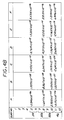
- Figure 4 is an optical prescription for an embodiment of the present approach.
- FIG. 1 depicts an infrared imaging optical system 20.
- the infrared imaging o ptical s ystem 2 0 includes a lens group 2 2 that focuses a n infrared light beam 24 from a scene onto an infrared detector 26.
- the infrared detector 26 is preferably a focal plane array (FPA) located at the focal plane of the lens group 22.
- the infrared detector 26 may be selected to be sensitive to any infrared wavelength or range of wavelengths. Preferably, it is sensitive to infrared wavelengths of from about 2 to about 7 micrometers wavelength, and more preferably the mid wavelength infrared range of from about 3 to about 5 micrometers wavelength. Infrared detectors 26 of these types and their manufacture are known in the art.
- the infrared detector 26 converts the incident infrared light beam 24 to an output signal 28, which is analyzed by image analysis electronics 30. Such image analysis electronics 30 is known in the art.
- the preferred infrared detector 24 operates most effectively and efficiently at cryogenic temperatures of about 77K.
- the infrared detector 26 is mounted to one end of a pedestal 32, and the other end of the pedestal 32 is mounted to a cryostat 34, such as a Joule-Thomson cryostat, to cool the infrared detector 26 to such a low temperature by conduction of heat through the pedestal 32.
- the infrared detector 26, the pedestal 32, and the cryostat 34 are enclosed in a vacuum dewar, which serves as a cold shield 36.
- the cold shield 36 is vacuum tight, and is evacuated by a vacuum pump 38.
- An opening 37 of the cold shield 36 is located at, and a window 40 of the cold shield 36 is located near (i.e., typically within 3 millimeters), an external pupil 42 of the lens group 22.
- a window 40 of the cold shield 36 is located near (i.e., typically within 3 millimeters), an external pupil 42 of the lens group 22.
- the pupil 42 of the lens group 22 it is necessary that the pupil 42 of the lens group 22 be external to the lens group 22. Stated alternatively, the pupil 42 must lie between the lens group 22 and the infrared detector 26. It cannot lie within the lens group 22, or the cold shield 36 would have to include at least one of the lenses of the lens group 22.
- the opening 37 (the "cold stop") of the cold shield 3 6 is at the external optics pupil 42. Otherwise, the detector 26 will detect energy from the lens surfaces and/or from some other component, such as a housing of the lens group 22, that is warm and is of high emissivity. The result is that the background signal reaching the detector 26 will greatly increase.
- the lens group 22 of the infrared imaging optical system 20 includes a front lens group 44 having negative optical power.
- the front lens group 44 has a front lens 46 with a refractive index of from about 2.0 to about 3.0, more preferably from about 2.2 to about 2.6.
- the infrared light beam 24 from the scene is incident upon the front lens group 44.
- the lens group 22 further includes an intermediate lens group 48 that receives the infrared light beam 24 from the front lens group 44.
- the intermediate lens group 44 includes two intermediate lenses 50, indicated as lenses 50a (which is closer to the front lens 46) and 50b (which is further from the front lens 46).
- the intermediate lens 50a is preferably made of an infrared-transparent material having a relatively high index of refraction of greater than about 3.0.
- the intermediate lens 50b is preferably made of an infrared-transparent material having a refractive index of from about 1.35 to about 2.0, more preferably from about 1.35 to about 1.7.
- the lens group 22 further includes a rear lens group 52 having positive optical power t hat r eceives the infrared light beam 2 4 from the intermediate lens group 48.
- the rear lens group 52 comprises a rear lens 54 having a refractive index of from about 2.0 to about 3.0, more preferably from about 2.2 to about 2.6.
- the lens group 22 is an "inverse-telephoto" lens group.
- the front lens 46 has a negative optical power
- the rear lens 54 has a positive optical power.
- This combination of optical powers allows the lens group 22 to function in the "fisheye” manner, with a very wide field of view in both the azimuth and elevation as depicted in Figures 1 and 2.
- the front lens 46, the intermediate lens 50, and the rear lens 54 have at least one aspheric surface thereon.
- the front lens 46, the intermediate lens 50a, the intermediate lens 50b, and the rear lens 54 are all relatively thin lenses that each have exactly one aspheric surface thereon.
- An aspheric surface is a surface that cannot be described by a spheric relation, and typically has higher-order terms.
- the pupil 42 is an "external pupil” that is located between the rear lens group 52 and the detector 26. This external pupil is necessary for the applications involving an evacuated cold shield 36.
- the lenses with a refractive index of from about 2.0 to about 3.0 are preferably made of an infrared-transparent material such as zinc sulfide, zinc selenide, arsenic trisulfide, or amtir1 (having a nominal composition of Ge 33 As 12 Se 55 ).
- the intermediate lens 50a having a relatively high index of refraction of greater than about 3.0 is preferably made of an infrared-transparent material such as germanium, silicon, or gallium arsenide.
- the intermediate lens 50b having a refractive index of from about 1.35 to about 2.0, is preferably made of an infrared-transparent material such as sapphire, spinel, barium fluoride, calcium fluoride, magnesium fluoride, or magnesium oxide.
- the value z is the sag of the surface parallel to the z-axis
- h 2 x 2 + y 2
- x and y are Cartesian coordinates in a plane perpendicular to the z-axis
- c is the curvature at the vertex of the surface
- k is the conic coefficient
- A, B, C, D, E, and F are constants.
- Figures 2 and 3 respectively illustrate the present approach and the prior approach, and are drawn to scale relative to each other.
- the present approach of Figure 4 herein produces a ratio of the physical length: focal length of about 10:1, while the prior art embodiment of Table 1 of the '581 patent has a ratio of the physical length:focal length of 21.5:1.
- the physical length PL is the distance from the outwardly facing surface of the front lens to the inwardly facing surface of the rear lens.
- the optical system of the present approach thus is much shorter in physical length than that of the prior approach.
- the diameters o f the lenses in the present approach are smaller than those of the prior approach, and the length of the required support structure is smaller, leading to reduced weight for the present approach.
- the reduced weight and size are important advantages for some applications such as those in aircraft.
- the reduced size and weight are achieved without a loss in optical performance, and in fact the optical performance of the present approach is superior to that of the embodiments of the '581 patent.
- the present approach of Figure 4 herein has a blur diameter of 1.9 mrad on-axis, 1.2 mrad at half-field, and 6.6 mrad at the field-of-view edge.
- the p rior approach o f Table 1 of the '581 patent has a blur diameter of 2.3 mrad on-axis, 2.6 mrad at half-field, and 9.0 mrad at the field-of-view edge.
- the image distortion was evaluated as a percentage departure from the f form.
- the departure of the approach of Table 1 of the '581 patent was 12 percent at the field-of-view edge, while the departure of the present approach of Figure 4 herein was 6 percent at the field-of-view edge.
- the physical size as measured by the ratio of the physical length to the effective focal length (PL:EFL).
- the various embodiments of the '581 patent have a ratio PL:EFL in the range of 20:1 to 30:1, while the present approach has a ratio PL:EFL in the range of 8:1 to 10:1.
- the '581 patent uses the standard mid-wavelength infrared materials germanium and silicon for lens construction. These materials have high refractive indices of about 4.0 and 3.4, respectively. These materials limit the ability t o correct field curvature and chromatic aberrations, important aberrations in the performance of very wide field of view inverse telephoto optical forms of this type. There are no other materials with refractive indices within about 0.1-0.2 of those of germanium and silicon. The dispersion of germanium is moderate and that of silicon is low. When these materials are used in the lenses, there are no material alternatives if the aberration correction dictates a slightly lower or higher refractive index for control of field curvature, or a slightly lower or higher dispersion for axial or lateral color correction.
- the present approach uses moderate-refractive-index materials such as zinc sulfide, zinc selenide, and amtir1, with refractive indices of about 2.25, 2.4, and 2.5, respectively, for the front lens 46 and the rear lens 54.
- the refractive index of the front lens 46 and/or the rear lens 54 may be raised or lowered slightly for correction of field curvature, because the refractive indices are near each other.
- the dispersions of these alternative materials are low for amtir1 and zinc selenide, and moderate for zinc sulfide. This allows a degree of chromatic aberration correction to be addressed at the same time as the field curvature is being corrected, by selecting the specific appropriate lens material.
- the present approach also uses the lower refractive index crystalline materials such as sapphire, spinel, and magnesium oxide, with respective refractive indices of about 1.66, 1.63, and 1.66, in the intermediate lens 50b of the intermediate lens group to assist in the final balance of chromatic aberration correction and field curvature.
- These three materials have significantly higher dispersion characteristics than any of the other materials used in the front and rear lens groups. Lenses with a moderate to low amount of negative optical power made from these materials subtly affect both field curvature and chromatic aberration due to the low refractive index and high dispersion.
- the present approach also allows the use of higher-order general aspheric surfaces in three important locations: near the external aperture stop nearest to the detector 26 for control of spherical aberration, near the center of the lens assembly for control of distortion, and on the large negative-power front lens for control of the field aberrations, coma, and astigmatism.
Landscapes
- Physics & Mathematics (AREA)
- General Physics & Mathematics (AREA)
- Optics & Photonics (AREA)
- Health & Medical Sciences (AREA)
- Toxicology (AREA)
- Lenses (AREA)
Applications Claiming Priority (2)
| Application Number | Priority Date | Filing Date | Title |
|---|---|---|---|
| US715678 | 2003-11-18 | ||
| US10/715,678 US6989537B2 (en) | 2003-11-18 | 2003-11-18 | Compact inverse-telephoto infrared imaging optical system |
Publications (2)
| Publication Number | Publication Date |
|---|---|
| EP1533638A1 true EP1533638A1 (de) | 2005-05-25 |
| EP1533638B1 EP1533638B1 (de) | 2008-06-04 |
Family
ID=34435724
Family Applications (1)
| Application Number | Title | Priority Date | Filing Date |
|---|---|---|---|
| EP04256812A Expired - Lifetime EP1533638B1 (de) | 2003-11-18 | 2004-11-04 | Kompaktes Fisheye - Infrarotobjektiv |
Country Status (3)
| Country | Link |
|---|---|
| US (1) | US6989537B2 (de) |
| EP (1) | EP1533638B1 (de) |
| DE (1) | DE602004014233D1 (de) |
Cited By (3)
| Publication number | Priority date | Publication date | Assignee | Title |
|---|---|---|---|---|
| FR2930049A1 (fr) * | 2008-04-15 | 2009-10-16 | Sagem Defense Securite | Objectif a athermalisation passive. |
| CN102866482A (zh) * | 2012-10-18 | 2013-01-09 | 南京波长光电科技有限公司 | 一种鱼眼红外镜头 |
| NO337098B1 (no) * | 2013-09-26 | 2016-01-18 | FLIR Unmanned Aerial Systems AS | Linsearrangement |
Families Citing this family (14)
| Publication number | Priority date | Publication date | Assignee | Title |
|---|---|---|---|---|
| KR100955975B1 (ko) * | 2006-01-30 | 2010-05-04 | 스미토모 덴키 고교 가부시키가이샤 | 적외선 렌즈, 적외선 카메라 및 나이트비전 |
| US7763857B2 (en) * | 2008-02-21 | 2010-07-27 | Raytheon Company | Infrared imaging optical system with varying focal length across the field of view |
| US8279520B2 (en) | 2010-07-30 | 2012-10-02 | Raytheon Company | Wide field of view LWIR high speed imager |
| US8294988B2 (en) | 2010-09-02 | 2012-10-23 | Raytheon Company | Dual field of view refractive optical system with external pupil and internal stabilization |
| US9025256B2 (en) | 2011-03-10 | 2015-05-05 | Raytheon Company | Dual field of view refractive optical system for GEO synchronous earth orbit |
| US9411137B2 (en) | 2011-09-26 | 2016-08-09 | Raytheon Company | Ultra compact inverse telephoto optical system for use in the IR spectrum |
| US9110276B2 (en) | 2012-01-20 | 2015-08-18 | Raytheon Company | Full-field GEO imager optics with extended spectral coverage |
| US8824055B2 (en) | 2012-11-16 | 2014-09-02 | Raytheon Company | Refractive optics with broad spectral coverage |
| DE102014117275B4 (de) | 2014-11-25 | 2016-06-23 | Airbus Ds Optronics Gmbh | Weitwinkelobjektiv |
| CN105911676A (zh) * | 2016-06-12 | 2016-08-31 | 中国科学院上海技术物理研究所 | 一种大相对孔径制冷型红外光学镜头 |
| US10670841B2 (en) | 2017-07-20 | 2020-06-02 | Raytheon Company | Two-color inverse telephoto refractive optical form with external pupil for cold shielding |
| US11268860B2 (en) | 2020-07-24 | 2022-03-08 | Raytheon Company | Radiometric calibration of detector |
| DE102020133691A1 (de) | 2020-12-16 | 2022-06-23 | Valeo Schalter Und Sensoren Gmbh | Infrarot-Wärmebildkamera und bordeigenes System zur Unterstützung des Führens eines eine solche Kamera aufweisenden Kraftfahrzeugs |
| US12566320B2 (en) | 2023-06-13 | 2026-03-03 | Bae Systems Information And Electronic Systems Integration Inc. | Panoramic MWIR lens for cooled detectors |
Citations (6)
| Publication number | Priority date | Publication date | Assignee | Title |
|---|---|---|---|---|
| US4679891A (en) * | 1984-07-14 | 1987-07-14 | Pilkington P.E. Limited | Infra-red lenses |
| US5446581A (en) * | 1993-03-15 | 1995-08-29 | Lockheed Missiles & Space Co., Inc. | Inverted telephoto wide-aperture wide-field infrared lens system |
| JPH07318797A (ja) * | 1994-05-27 | 1995-12-08 | Minolta Co Ltd | 赤外線用レンズ |
| US5502592A (en) * | 1993-11-22 | 1996-03-26 | Lockheed Missiles & Space Company, Inc. | Wide-aperture infrared lenses with hyper-hemispherical fields of view |
| JPH1123962A (ja) * | 1997-06-27 | 1999-01-29 | Fuji Photo Optical Co Ltd | 赤外線レンズ |
| JP2002196233A (ja) * | 2000-12-26 | 2002-07-12 | Nikon Corp | 赤外光学系及びこれを備えた赤外光学装置 |
Family Cites Families (3)
| Publication number | Priority date | Publication date | Assignee | Title |
|---|---|---|---|---|
| JPS53132360A (en) * | 1977-04-25 | 1978-11-18 | Canon Inc | Wide angle zoom lens of small size |
| US4600265A (en) * | 1983-01-27 | 1986-07-15 | Pilkington P.E. Limited | Infra-red optical systems |
| GB9809738D0 (en) * | 1998-05-08 | 1998-07-08 | Pilkington Perkin Elmer Ltd | Optical systems |
-
2003
- 2003-11-18 US US10/715,678 patent/US6989537B2/en not_active Expired - Lifetime
-
2004
- 2004-11-04 EP EP04256812A patent/EP1533638B1/de not_active Expired - Lifetime
- 2004-11-04 DE DE602004014233T patent/DE602004014233D1/de not_active Expired - Lifetime
Patent Citations (6)
| Publication number | Priority date | Publication date | Assignee | Title |
|---|---|---|---|---|
| US4679891A (en) * | 1984-07-14 | 1987-07-14 | Pilkington P.E. Limited | Infra-red lenses |
| US5446581A (en) * | 1993-03-15 | 1995-08-29 | Lockheed Missiles & Space Co., Inc. | Inverted telephoto wide-aperture wide-field infrared lens system |
| US5502592A (en) * | 1993-11-22 | 1996-03-26 | Lockheed Missiles & Space Company, Inc. | Wide-aperture infrared lenses with hyper-hemispherical fields of view |
| JPH07318797A (ja) * | 1994-05-27 | 1995-12-08 | Minolta Co Ltd | 赤外線用レンズ |
| JPH1123962A (ja) * | 1997-06-27 | 1999-01-29 | Fuji Photo Optical Co Ltd | 赤外線レンズ |
| JP2002196233A (ja) * | 2000-12-26 | 2002-07-12 | Nikon Corp | 赤外光学系及びこれを備えた赤外光学装置 |
Non-Patent Citations (3)
| Title |
|---|
| PATENT ABSTRACTS OF JAPAN vol. 1996, no. 04 30 April 1996 (1996-04-30) * |
| PATENT ABSTRACTS OF JAPAN vol. 1999, no. 04 30 April 1999 (1999-04-30) * |
| PATENT ABSTRACTS OF JAPAN vol. 2002, no. 11 6 November 2002 (2002-11-06) * |
Cited By (3)
| Publication number | Priority date | Publication date | Assignee | Title |
|---|---|---|---|---|
| FR2930049A1 (fr) * | 2008-04-15 | 2009-10-16 | Sagem Defense Securite | Objectif a athermalisation passive. |
| CN102866482A (zh) * | 2012-10-18 | 2013-01-09 | 南京波长光电科技有限公司 | 一种鱼眼红外镜头 |
| NO337098B1 (no) * | 2013-09-26 | 2016-01-18 | FLIR Unmanned Aerial Systems AS | Linsearrangement |
Also Published As
| Publication number | Publication date |
|---|---|
| DE602004014233D1 (de) | 2008-07-17 |
| US20050103999A1 (en) | 2005-05-19 |
| US6989537B2 (en) | 2006-01-24 |
| EP1533638B1 (de) | 2008-06-04 |
Similar Documents
| Publication | Publication Date | Title |
|---|---|---|
| EP1533638B1 (de) | Kompaktes Fisheye - Infrarotobjektiv | |
| US7763857B2 (en) | Infrared imaging optical system with varying focal length across the field of view | |
| EP1405119B1 (de) | Thermisch stabilisiertes diffraktives infrarot-zoom-objektiv | |
| EP4235250B1 (de) | Zweifarbige refraktive okularartige optische form mit sehr grossem sichtfeld | |
| AU2008311392A1 (en) | Compact two-element infrared objective lens and IR or thermal sight for weapon having viewing optics | |
| CN106772959B (zh) | 一种短波、长波红外双波段共焦面大相对孔径光学系统 | |
| CN111025529B (zh) | 一种超小f数中长波红外定焦镜头 | |
| US9411137B2 (en) | Ultra compact inverse telephoto optical system for use in the IR spectrum | |
| IL270713A (en) | Bi-color inverted telephoto breaking optical shape with external pupil for cold shielding | |
| CN114137699B (zh) | 一种小型高分辨率无热化中波红外光学系统 | |
| US11860345B2 (en) | Midwave infrared discrete zoom lens | |
| CN214201901U (zh) | 大视场光学成像镜头及其构成的光学系统 | |
| US20060028713A1 (en) | Optical imager for the 3-5 micron spectral band | |
| US5282083A (en) | Afocal lens system | |
| CN119165625B (zh) | 一种光学被动无热化长波红外折衍混合光学系统 | |
| CN116661117B (zh) | 折反式光学成像系统 | |
| Bodkin et al. | Compact multi-band (VIS/IR) zoom imager for high resolution long range surveillance | |
| CN116661116B (zh) | 一种共光路的中波长波双色消热差制冷型红外折反光学系统 | |
| JPH1123962A (ja) | 赤外線レンズ | |
| CN102980666A (zh) | 高精度小型化红外光学系统 | |
| CN121477447A (zh) | 一种小型化热成像观瞄镜头和热成像观瞄设备 | |
| CN121956349A (zh) | 一种高分辨率红外双波段曲面仿生复眼光学系统 | |
| CN121325373A (zh) | 中波制冷探测器及其无热化镜头 | |
| Zhang et al. | Design of reimaging F/1.0 long-wavelength infrared optical system | |
| Ucar et al. | Optical design of a broadband (3-12 µm) athermal infrared imager |
Legal Events
| Date | Code | Title | Description |
|---|---|---|---|
| PUAI | Public reference made under article 153(3) epc to a published international application that has entered the european phase |
Free format text: ORIGINAL CODE: 0009012 |
|
| AK | Designated contracting states |
Kind code of ref document: A1 Designated state(s): AT BE BG CH CY CZ DE DK EE ES FI FR GB GR HU IE IS IT LI LU MC NL PL PT RO SE SI SK TR |
|
| AX | Request for extension of the european patent |
Extension state: AL HR LT LV MK YU |
|
| 17P | Request for examination filed |
Effective date: 20051103 |
|
| AKX | Designation fees paid |
Designated state(s): DE FR GB |
|
| GRAP | Despatch of communication of intention to grant a patent |
Free format text: ORIGINAL CODE: EPIDOSNIGR1 |
|
| GRAS | Grant fee paid |
Free format text: ORIGINAL CODE: EPIDOSNIGR3 |
|
| GRAA | (expected) grant |
Free format text: ORIGINAL CODE: 0009210 |
|
| AK | Designated contracting states |
Kind code of ref document: B1 Designated state(s): DE FR GB |
|
| REG | Reference to a national code |
Ref country code: GB Ref legal event code: FG4D |
|
| REF | Corresponds to: |
Ref document number: 602004014233 Country of ref document: DE Date of ref document: 20080717 Kind code of ref document: P |
|
| PLBE | No opposition filed within time limit |
Free format text: ORIGINAL CODE: 0009261 |
|
| STAA | Information on the status of an ep patent application or granted ep patent |
Free format text: STATUS: NO OPPOSITION FILED WITHIN TIME LIMIT |
|
| 26N | No opposition filed |
Effective date: 20090305 |
|
| REG | Reference to a national code |
Ref country code: FR Ref legal event code: PLFP Year of fee payment: 12 |
|
| REG | Reference to a national code |
Ref country code: FR Ref legal event code: PLFP Year of fee payment: 13 |
|
| REG | Reference to a national code |
Ref country code: FR Ref legal event code: PLFP Year of fee payment: 14 |
|
| REG | Reference to a national code |
Ref country code: FR Ref legal event code: PLFP Year of fee payment: 15 |
|
| PGFP | Annual fee paid to national office [announced via postgrant information from national office to epo] |
Ref country code: FR Payment date: 20221021 Year of fee payment: 19 |
|
| PGFP | Annual fee paid to national office [announced via postgrant information from national office to epo] |
Ref country code: GB Payment date: 20221021 Year of fee payment: 19 Ref country code: DE Payment date: 20220616 Year of fee payment: 19 |
|
| P01 | Opt-out of the competence of the unified patent court (upc) registered |
Effective date: 20230630 |
|
| REG | Reference to a national code |
Ref country code: DE Ref legal event code: R119 Ref document number: 602004014233 Country of ref document: DE |
|
| GBPC | Gb: european patent ceased through non-payment of renewal fee |
Effective date: 20231104 |
|
| PG25 | Lapsed in a contracting state [announced via postgrant information from national office to epo] |
Ref country code: DE Free format text: LAPSE BECAUSE OF NON-PAYMENT OF DUE FEES Effective date: 20240601 |
|
| PG25 | Lapsed in a contracting state [announced via postgrant information from national office to epo] |
Ref country code: GB Free format text: LAPSE BECAUSE OF NON-PAYMENT OF DUE FEES Effective date: 20231104 |
|
| PG25 | Lapsed in a contracting state [announced via postgrant information from national office to epo] |
Ref country code: FR Free format text: LAPSE BECAUSE OF NON-PAYMENT OF DUE FEES Effective date: 20231130 |
|
| PG25 | Lapsed in a contracting state [announced via postgrant information from national office to epo] |
Ref country code: GB Free format text: LAPSE BECAUSE OF NON-PAYMENT OF DUE FEES Effective date: 20231104 Ref country code: FR Free format text: LAPSE BECAUSE OF NON-PAYMENT OF DUE FEES Effective date: 20231130 Ref country code: DE Free format text: LAPSE BECAUSE OF NON-PAYMENT OF DUE FEES Effective date: 20240601 |