EP1533605A2 - Micro control system for transfer of liquids - Google Patents
Micro control system for transfer of liquids Download PDFInfo
- Publication number
- EP1533605A2 EP1533605A2 EP04078160A EP04078160A EP1533605A2 EP 1533605 A2 EP1533605 A2 EP 1533605A2 EP 04078160 A EP04078160 A EP 04078160A EP 04078160 A EP04078160 A EP 04078160A EP 1533605 A2 EP1533605 A2 EP 1533605A2
- Authority
- EP
- European Patent Office
- Prior art keywords
- liquid
- droplets
- channel
- droplet
- sorting
- Prior art date
- Legal status (The legal status is an assumption and is not a legal conclusion. Google has not performed a legal analysis and makes no representation as to the accuracy of the status listed.)
- Withdrawn
Links
Images




Classifications
-
- B—PERFORMING OPERATIONS; TRANSPORTING
- B03—SEPARATION OF SOLID MATERIALS USING LIQUIDS OR USING PNEUMATIC TABLES OR JIGS; MAGNETIC OR ELECTROSTATIC SEPARATION OF SOLID MATERIALS FROM SOLID MATERIALS OR FLUIDS; SEPARATION BY HIGH-VOLTAGE ELECTRIC FIELDS
- B03C—MAGNETIC OR ELECTROSTATIC SEPARATION OF SOLID MATERIALS FROM SOLID MATERIALS OR FLUIDS; SEPARATION BY HIGH-VOLTAGE ELECTRIC FIELDS
- B03C9/00—Electrostatic separation not provided for in any single one of the other main groups of this subclass
-
- B—PERFORMING OPERATIONS; TRANSPORTING
- B01—PHYSICAL OR CHEMICAL PROCESSES OR APPARATUS IN GENERAL
- B01L—CHEMICAL OR PHYSICAL LABORATORY APPARATUS FOR GENERAL USE
- B01L3/00—Containers or dishes for laboratory use, e.g. laboratory glassware; Droppers
- B01L3/50—Containers for the purpose of retaining a material to be analysed, e.g. test tubes
- B01L3/502—Containers for the purpose of retaining a material to be analysed, e.g. test tubes with fluid transport, e.g. in multi-compartment structures
- B01L3/5027—Containers for the purpose of retaining a material to be analysed, e.g. test tubes with fluid transport, e.g. in multi-compartment structures by integrated microfluidic structures, i.e. dimensions of channels and chambers are such that surface tension forces are important, e.g. lab-on-a-chip
- B01L3/502761—Containers for the purpose of retaining a material to be analysed, e.g. test tubes with fluid transport, e.g. in multi-compartment structures by integrated microfluidic structures, i.e. dimensions of channels and chambers are such that surface tension forces are important, e.g. lab-on-a-chip specially adapted for handling suspended solids or molecules independently from the bulk fluid flow, e.g. for trapping or sorting beads or physically stretching molecules
-
- B—PERFORMING OPERATIONS; TRANSPORTING
- B01—PHYSICAL OR CHEMICAL PROCESSES OR APPARATUS IN GENERAL
- B01L—CHEMICAL OR PHYSICAL LABORATORY APPARATUS FOR GENERAL USE
- B01L3/00—Containers or dishes for laboratory use, e.g. laboratory glassware; Droppers
- B01L3/50—Containers for the purpose of retaining a material to be analysed, e.g. test tubes
- B01L3/502—Containers for the purpose of retaining a material to be analysed, e.g. test tubes with fluid transport, e.g. in multi-compartment structures
- B01L3/5027—Containers for the purpose of retaining a material to be analysed, e.g. test tubes with fluid transport, e.g. in multi-compartment structures by integrated microfluidic structures, i.e. dimensions of channels and chambers are such that surface tension forces are important, e.g. lab-on-a-chip
- B01L3/502769—Containers for the purpose of retaining a material to be analysed, e.g. test tubes with fluid transport, e.g. in multi-compartment structures by integrated microfluidic structures, i.e. dimensions of channels and chambers are such that surface tension forces are important, e.g. lab-on-a-chip characterised by multiphase flow arrangements
- B01L3/502784—Containers for the purpose of retaining a material to be analysed, e.g. test tubes with fluid transport, e.g. in multi-compartment structures by integrated microfluidic structures, i.e. dimensions of channels and chambers are such that surface tension forces are important, e.g. lab-on-a-chip characterised by multiphase flow arrangements specially adapted for droplet or plug flow, e.g. digital microfluidics
-
- G—PHYSICS
- G01—MEASURING; TESTING
- G01N—INVESTIGATING OR ANALYSING MATERIALS BY DETERMINING THEIR CHEMICAL OR PHYSICAL PROPERTIES
- G01N15/00—Investigating characteristics of particles; Investigating permeability, pore-volume or surface-area of porous materials
- G01N15/10—Investigating individual particles
- G01N15/14—Optical investigation techniques, e.g. flow cytometry
- G01N15/1456—Optical investigation techniques, e.g. flow cytometry without spatial resolution of the texture or inner structure of the particle, e.g. processing of pulse signals
- G01N15/1459—Optical investigation techniques, e.g. flow cytometry without spatial resolution of the texture or inner structure of the particle, e.g. processing of pulse signals the analysis being performed on a sample stream
-
- G—PHYSICS
- G01—MEASURING; TESTING
- G01N—INVESTIGATING OR ANALYSING MATERIALS BY DETERMINING THEIR CHEMICAL OR PHYSICAL PROPERTIES
- G01N15/00—Investigating characteristics of particles; Investigating permeability, pore-volume or surface-area of porous materials
- G01N15/10—Investigating individual particles
- G01N15/14—Optical investigation techniques, e.g. flow cytometry
- G01N15/1484—Optical investigation techniques, e.g. flow cytometry microstructural devices
-
- B—PERFORMING OPERATIONS; TRANSPORTING
- B01—PHYSICAL OR CHEMICAL PROCESSES OR APPARATUS IN GENERAL
- B01L—CHEMICAL OR PHYSICAL LABORATORY APPARATUS FOR GENERAL USE
- B01L2200/00—Solutions for specific problems relating to chemical or physical laboratory apparatus
- B01L2200/06—Fluid handling related problems
- B01L2200/061—Counting droplets
-
- B—PERFORMING OPERATIONS; TRANSPORTING
- B01—PHYSICAL OR CHEMICAL PROCESSES OR APPARATUS IN GENERAL
- B01L—CHEMICAL OR PHYSICAL LABORATORY APPARATUS FOR GENERAL USE
- B01L2200/00—Solutions for specific problems relating to chemical or physical laboratory apparatus
- B01L2200/06—Fluid handling related problems
- B01L2200/0673—Handling of plugs of fluid surrounded by immiscible fluid
-
- B—PERFORMING OPERATIONS; TRANSPORTING
- B01—PHYSICAL OR CHEMICAL PROCESSES OR APPARATUS IN GENERAL
- B01L—CHEMICAL OR PHYSICAL LABORATORY APPARATUS FOR GENERAL USE
- B01L2300/00—Additional constructional details
- B01L2300/08—Geometry, shape and general structure
- B01L2300/0861—Configuration of multiple channels and/or chambers in a single devices
- B01L2300/0864—Configuration of multiple channels and/or chambers in a single devices comprising only one inlet and multiple receiving wells, e.g. for separation, splitting
-
- B—PERFORMING OPERATIONS; TRANSPORTING
- B01—PHYSICAL OR CHEMICAL PROCESSES OR APPARATUS IN GENERAL
- B01L—CHEMICAL OR PHYSICAL LABORATORY APPARATUS FOR GENERAL USE
- B01L2400/00—Moving or stopping fluids
- B01L2400/04—Moving fluids with specific forces or mechanical means
- B01L2400/0403—Moving fluids with specific forces or mechanical means specific forces
- B01L2400/0415—Moving fluids with specific forces or mechanical means specific forces electrical forces, e.g. electrokinetic
-
- B—PERFORMING OPERATIONS; TRANSPORTING
- B01—PHYSICAL OR CHEMICAL PROCESSES OR APPARATUS IN GENERAL
- B01L—CHEMICAL OR PHYSICAL LABORATORY APPARATUS FOR GENERAL USE
- B01L3/00—Containers or dishes for laboratory use, e.g. laboratory glassware; Droppers
- B01L3/02—Burettes; Pipettes
- B01L3/0241—Drop counters; Drop formers
-
- G—PHYSICS
- G01—MEASURING; TESTING
- G01N—INVESTIGATING OR ANALYSING MATERIALS BY DETERMINING THEIR CHEMICAL OR PHYSICAL PROPERTIES
- G01N15/00—Investigating characteristics of particles; Investigating permeability, pore-volume or surface-area of porous materials
- G01N15/10—Investigating individual particles
- G01N15/14—Optical investigation techniques, e.g. flow cytometry
- G01N15/149—Optical investigation techniques, e.g. flow cytometry specially adapted for sorting particles, e.g. by their size or optical properties
Definitions
- This invention relates to a micro liquid control system which selects and sorts target objects such as droplets.
- the droplets may be sorted according to fine particulate material, such as cell material, which they contain, making the system suitable for use in flow cytometers.
- prior Patent document 1 discloses a handling apparatus for fine liquid particles wherein a plurality of electrodes is arranged to form an electrode array on a substrate; droplets of agents and specimen are formed; the droplets are put on the hydrophobic surface; transporting of the droplets is performed by electrostatic force with the voltage application in sequence to the electrode array.
- the phase surrounding the droplets is not liquid phase but gas phase.
- the droplets are transported using an electrostatic force by applying a voltage to the electrode array in sequence and hence a pump to transport the droplets is not necessary.
- Patent document 2 discloses a flow control technology in a micro system wherein a material which is converted between sol and gel by an external stimulation is added to a liquid which flows through a fine flow channel in the micro system. By applying a stimulation to an appropriate part of the fine flow channel, the liquid is converted to gel to form a barrier. The barrier is converted back to the liquid phase when the stimulation is removed so that the flow of the liquid is controlled.
- a closing valve is formed by utilizing the phase change from sol to gel and an opening valve is formed by utilizing the phase change from gel to sol.
- Patent document 3 discloses a micro cell sorter wherein a cell is placed in an electrolyte solution containing ions, and an electric current is applied to an electrode inserted in the electrolyte solution to select the cell.
- droplets are transported with an array of electrodes, which do not select the droplets according to species of the individual droplets.
- the droplets are transported in aerosol form, and because the droplets are transported with electrostatic force, the transportation speed is slow and the system is not suitable for a high speed, large quantity processing. Furthermore, since the phase surrounding the droplets is not liquid phase but gas phase, the droplets easily evaporate.
- a micro specimen flows along with the flow of a liquid.
- the response time is slow and it is not suitable for high speed, large quantity processing.
- the system creates a closing valve using the phase change from sol to gel and an opening valve using the phase change from gel to sol, the flow stagnates around the valves and is easily choked so that the controllability of the liquid is not good enough.
- the present invention provides a micro liquid control system in which a micro target object such as a droplet is carried by a flow of a first liquid. It has an objective of high speed and large quantity processing and also it can select and sort the target objects in units.
- the invention is as specified in claim 1.
- the sorting means comprises means for establishing an electrostatic field through which the charged droplets flow.
- the electrostatic field is established between a pair of electrodes which move the droplets flowing in the main channel with an attractive or repulsive force depending on the electrical charge carried by the individual droplets, so that target droplets are selectively diverted to be collected together in the sorting channel means.
- the sorting means comprises means for establishing a magnetic field through which the charged droplets flow.
- the magnetic field moves the droplets flowing in the main channel with an electromagnetic force in a direction, which depends on the electrical charge carried by the individual droplets, so that target droplets are selectively diverted to be collected together in the sorting channel means.
- the target object is electrically charged during the formation of the droplet target object.
- “period during the formation of the droplet target object” refers to the status just before the formation of the droplet target object, the status during the process of formation of the droplet target object, or the status just after the formation of the droplet target object.
- the micro target object may be droplets or micro particles of 2 mm or less, or 1 mm or less, or 0.1 mm or less.
- Fig. 1 shows a micro liquid control system of the first embodiment.
- the micro liquid control system comprises a microchannel 1 through which flows at least one droplet 9 as target object together with main liquid 14.
- the system also comprises a droplet forming means 5 which forms droplets 9 suspended in main liquid 14, a droplet counting means 6 which counts formed droplets 9, and a sorting means 4 which sorts the droplets 9.
- the system comprises an electrical charging means 3A which charges the droplets 9.
- the electrical charging means 3A is provided at the upstream side of the droplet counting means 6.
- a microchannel 1 is provided in a transparent substrate 18 made of resin or glass.
- the microchannel 1 comprises a main channel 10 which carries a flow of a first liquid, or main liquid, 14 in which small size droplets 9 as a small target object are dispersed and a sorting channel means 12 which is provided at the downstream side of the main channel 10 to receive the sorted target objects.
- a pump 15 is provided which discharges the main liquid 14 to the microchannel 1 to create a flow in the direction of the arrow A1.
- the sorting channel means 12 has a Y branch at the downstream side of the main channel 10 to form a first sorting channel 121 and a second sorting channel 122.
- a droplet selecting means 2 target object selecting means
- Fig.3 is provided which selects the droplets 9 which flow in the microchannel 1 and supplies them to the sorting channel means 12.
- the system also includes a droplet forming means 5 (target object forming means) which forms the droplets 9 and flows them to the downstream side, and a droplet counting means 6 (target object counting means) which detects and counts the droplets 9 formed by the droplet forming means 5. And, an information detecting means 7A which performs detection processing of the target objects (droplets 9) and detects information about the target objects.
- a droplet forming means 5 target object forming means
- a droplet counting means 6 target object counting means
- an information detecting means 7A which performs detection processing of the target objects (droplets 9) and detects information about the target objects.
- the droplet forming means 5 includes a droplet forming channel 50.
- the droplet forming channel 50 is a side channel through which flows a second liquid, or parent phase liquid, 52 which is the parent phase of the droplets 9.
- the channel 50 intersects at a junction 54 with the upstream side of the main channel 10, just downstream of the pump 15.
- a pump 55 discharges the parent phase liquid 52 into the droplet forming channel 50 to create a flow in the direction of the arrow B1 (Fig. 1).
- the parent phase liquid 52 which is discharged into the main channel 1 at the junction 54 is separated by the sheer force of the main liquid 14 which flows in the main channel 10, and droplets 9 are formed.
- the average diameter of the formed droplets 9 depends on the type of the liquid and may be 1,000 ⁇ m or less, or 500 ⁇ m or less, or 300 ⁇ m or less, and may be 1 to 800 ⁇ m, or especially 2 to 500 ⁇ m or 4 to 300 ⁇ m. But the size of the droplets 9 is not limited to these values.
- the parent phase liquid 52 may comprise water as its main component.
- the main liquid 14 may comprise a material that has a high electric insulating property and low solubility in water, such as oil or a fluorocarbon which are hydrophobic.
- the oil may be chosen from, for example, sunflower oil, olive oil, tung oil, linseed oil, silicone oil and mineral oil. The lubricating qualities of the oil improve its passage through the main channel 10.
- the main component of the parent phase liquid 52 is water which is electrically conductive and has a larger dielectric constant than that of the oily main liquid 14.
- the formed droplets 9 are so-called water-in-oil type droplets.
- the formed droplets 9 flow with the main liquid 14 in the main channel 10 of the microchannel 1 in the direction of the sorting channel 12 (in the direction of Arrow A2).
- the individual droplets 9 flow in the microchannel 1 to the downstream side in the direction of the arrow A2
- the individual droplets are entrained in the main liquid 14. Since the oil-based main liquid 14 has a low solubility in the parent phase liquid 52, the droplets 9 flow stably in the downstream direction with little mixing between the lyophobic and hydrophobic components.
- an information detecting means 7A is provided near a detecting position 10rA of the main channel 10 of the microchannel 1.
- an optical detection means is preferably adopted as the information detecting means 7A, which comprises optical fibres 70 and 71 whose extremities face the detecting position 10rA; a light emitting part 72 including a laser element which emits a laser beam to the other end of the fibre 71; a light receiving part 73 which receives light irradiated from the droplet 9; a detecting part 74 which detects information about the target object based upon the signal received by a light receiving part 73.
- the main components 72, 73 and 74 of the optical system of the information detecting part 7A can be provided away from the droplet 9 where they do not get in the way.
- the electrical charging means 3A is provided between the downstream side of the junction 54 and the upstream side of a droplet counting part 6 very close to the junction 54.
- the electrical charging means 3A has a charging electrode 31A.
- This charging electrode 31A can be connected to a power source 34A or 35A through a switch 33A.
- terminals 33Aa and 33Ac are connected by the switch 33A, the polarity of the charging electrode 31A is positive.
- the terminals 33Ab and 33Ac are connected by the switch 33A, the polarity of the charging electrode 31A becomes negative. Accordingly, the switch 33A operates as a polarity switching means for the charging electrode 31A.
- the charging electrode 31A is provided, as shown in Fig. 2, over a microchannel 1 (especially a main channel 10). That is, as shown in Fig. 1, the parent phase liquid 52 passing from the droplet forming channel 50 through the junction 54 is pushed by the main liquid 14 in the microchannel 1, and when the extremity part, or leading surface or boundary, 52a of the parent phase liquid 52 takes a position just below the downstream side of the junction 54 in the main channel 10, the charging electrode 31A is arranged to be right above the extremity part 52a of the parent phase liquid 52.
- one end of a conductor 36A is arranged to make contact with the parent phase liquid 52 in the droplet forming channel 50 and the other end of the conductor 36A is connected to ground potential. Accordingly, the parent phase liquid 52 in the droplet forming channel 50 is connected to ground potential through the conductor 36A.
- the extremity part 52a immediately before the droplet 9 is formed, can be electrically charged by the charging electrode 31A.
- the polarity of the charge of the droplet 9 can be selected to be positive or negative by changing the polarity of the charging electrode 31A.
- the parent phase liquid 52 may be, for example, a cell suspension containing a cell.
- the cell contained in the parent phase liquid 52 entering into the cross area 54 is a target cell which has a special characteristic, the droplet 9, is charged to be positive or negative.
- the droplet 9 is charged to be negative when the cell is the target cell having the special characteristic.
- the charging electrode 31A is made positive by the connection to the power source 35A through the switch 33A. With this, when the extremity part 52a of the parent phase liquid 52 entering into the junction 54 approaches the charging electrode 31A, the part of the extremity part 52a which faces the charging electrode 31A tends to become negative by electrostatic induction. In addition, the part which is far from the charging electrode 31A tends to become positive.
- the parent phase liquid 52 still in the droplet forming channel 50 is connected to ground potential through the terminal 36A, and the excessive positive charge (the charge with the same polarity as that of the charging electrode 31A) induced in the extremity part 52a escapes to the conductor 36A through the parent phase liquid 52 in the droplet forming channel 50 (charge discharge mechanism). Therefore, the extremity part 52a just before being severed from the parent phase liquid 52 in the channel 50 has a negative polarity. As a result, the droplet 9 has a negative polarity after being severed.
- the charging electrode 31A is connected to the power source 34A through the switch 33A and the polarity of the charging electrode 31A becomes negative. Accordingly the extremity part 52a just before being severed has a positive polarity and the droplet 9 has a positive polarity after it is severed.
- the droplet 9 is charged to a negative polarity when it contains a target cell which has the special characteristic, and the droplet 9 is charged to a positive polarity when it contains no target cell, but the opposite polarity assignment may be adopted as well.
- the target selecting means 7A provided at the detecting position 10rA near the junction 54.
- inspecting light is irradiated onto the cell contained inside the droplet 9. In this case, the inspecting light is projected to the cell contained in the extremity part 52a just before being severed or to the cell contained in the parent phase liquid 52 before being transferred to the extremity part 52a.
- the target selecting means 7A can identify individual droplets containing selected target cells or other target fine particulate material.
- the droplet size and the concentration of the fine particulate material dispersed in the parent liquid 52 is such as to create a monodisperse suspension of at most one fine particle per droplet 9.
- the droplets 9 selected as containing target material become target droplets 9, and the electrical charging means 3A is controlled, by controlling the switch 33A, to provide a selected positive or negative electric charge to only those target droplets 9.
- the parent phase liquid 52 itself in the droplet forming channel 50 is connected to ground potential by the conductor 36A, this means that the extremity part 52a just before being severed is grounded to the conductor 36A through the parent phase liquid 52 in the droplet forming channel 50. Therefore, the excessive charge of the extremity part 52a or the cell contained in the extremity part 52a which has the same polarity as that of the charging electrode 31A can be dissipated through the conductor 36A.
- the information detecting means 7A which detects whether it is the target cell or not must be provided at the upstream side of the charging electrode 31A which charges the extremity part 52a.
- the target selecting means 7A is arranged at the detecting position 10rA near the junction 54 at the upstream side of the charging electrode 31A.
- the inspecting light irradiates a narrow liquid width area 54r of the detecting position 10rA where the liquid width is narrowed. Since the liquid width area 54r which is irradiated by the inspecting light is narrow, a fluctuation of the cell position in the direction of the liquid width is suppressed and hence a cell detection fluctuation is suppressed.
- the sorting means 4 comprises a first selecting electrode 41 and a second selecting electrode 42 which are provided at opposite sides of the main channel 10.
- the first selecting electrode 41 has a positive polarity while the second selecting electrode 42 has a negative polarity, although they are not limited to this polarity arrangement but may be polarized oppositely.
- the droplet 9 of the predetermined polarity arrives at the sorting means 4 from the electrical charging part 3A, the droplet 9 is sorted according to its polarity. That is, if the droplet 9 has a negative polarity, the droplet 9 is attracted by the first selecting electrode 41 of positive polarity by electrostatic attractive force (Coulomb's force) and flows into a first sorting channel 121 in the direction of the arrow A3. The diversion into the first sorting channel 121 is assisted by the second selecting electrode 42 which has the same negative polarity as that of the droplet 9 and provides an electrostatic repulsive force (Coulomb's force) to the droplet 9.
- the first selecting electrode 41 of positive polarity by electrostatic attractive force (Coulomb's force)
- the diversion into the first sorting channel 121 is assisted by the second selecting electrode 42 which has the same negative polarity as that of the droplet 9 and provides an electrostatic repulsive force (Coulomb's force) to the droplet 9.
- the droplet Conversely if the droplet has a positive polarity, it is diverted into the second sorting channel 122.
- each droplet 9 can be sorted in units into the first sorting channel 121 or into the second sorting channel 122 according to the information of the droplet 9 of the target object. With this, it becomes possible to sort the droplet 9 in units of nano-litres, pico-litres, or femto-litres.
- the droplet 9 is a droplet which contains a fine particle such as a cell
- the fine particle can be kept inside the droplet 9, and the droplet 9 can be sorted in any of the above units into the first sorting channel 121 or into the second sorting channel 122. The diffusion of the fine particles to the outside of the droplets 9 is suppressed.
- the droplets 9 are carried downstream together with the main liquid 14.
- the transportation speed of the droplet 9 is higher which is advantageous from the point of high speed and large quantity processing.
- no valves are used to control the flow and a valve-less liquid system is possible.
- the malfunction such as flow stagnation or clogging due to the use of valves can be suppressed.
- the insulating property of the main liquid 14 is high, the heating of the main liquid 14 can be suppressed.
- an electrostatic field of the opposite or the same polarity as that of the target object is used to divert each target object into respective sorting channels.
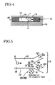
- Fig. 5 shows a second embodiment. Also, in this embodiment, in a manner similar to the first embodiment shown in Fig. 1, a droplet forming means 5, a droplet counting means 6 and an information detecting means 7 are provided at the upstream side of a main channel 10 of a microchannel 1. Since the configuration and its function are the same as those of the first embodiment, the description and the figure will not be repeated. Common parts are identified by common reference numerals.
- the microchannel 1 comprises a main channel 10 receiving a flow of a main liquid 14 in which fine size droplets 9 are dispersed and a sorting channel means 12 which sorts the droplets 9 at the downstream side of the main channel 10.
- the sorting channel means 12 has a Y configuration at the downstream side of the main channel 10 and comprises a first sorting channel 121 and a second sorting channel 122.
- the second embodiment differs from the first embodiment in that a different droplet selecting means 2B is provided, which functions as a selecting means of a target object to select the droplet 9 and supply it into the sorting means 12.
- the droplet selecting means 2B is provided at the downstream side of the above-described detecting position 10rA.
- the droplet selecting means 2B comprises the same electrical charging part 3A (Fig. 2) as that of the first embodiment, giving an electrical charge of a selected polarity to each droplet 9 flowing toward the downstream side (direction of the arrow A2) in the main channel 10 and a sorting means 4B (Fig. 5) which sorts the charged droplets 9.
- the sorting means 4B comprises a magnetic field generating means 8.
- the magnetic field generating means 8 is provided at the downstream side of the electrical charging part 3A and applies an electromagnetic force to the moving charged droplets 9. With this, the droplets 9 are diverted and sorted in the sorting channel means 12.
- the magnetic field generating means 8 generates a magnetic field which is perpendicular to the main channel 10 of the microchannel 1. That is, it generates a magnetic field which is perpendicular to the paper surface of Fig. 5 and in the direction from above the paper sheet to below.
- a droplet 9 carried by the main liquid flow 14 is negatively charged, then according to Fleming's left-hand rule, a magnetic force in the direction of the arrow FA is applied to the droplet 9. Accordingly, the droplet 9 flows into the sorting channel 122 in the direction of the arrow A4 and is sorted in the sorting channel 122.
- the droplets 9 can be sorted into the first sorting channel 121 or into the second sorting channel 122.
- the droplets 9 can be sorted into the first sorting channel 121 or into the second sorting channel 122.
- the droplets 9 can be sorted in units of nano-litres, pico-litres, or femto-litres. All of the flexibility of use and advantages over the prior art described above with reference to the first embodiment are also attainable with this second embodiment in which the sorting is achieved by the magnetic field generating means which is provided at the downstream side of the charging means.
- Fig. 6 shows one example of the above-described droplet counting means 6.
- the droplet counting means 6 light transmission-type, detects individual droplets 9 and counts the number of droplets 9.
- the droplet counting means 6 comprises a light transmission element 60 and a light receiving element 61 which sandwich the main channel 10 of the microchannel 1 through which the droplets 9 flow.
- the light projected by the light sending part 60 is transmitted to the side of the light receiving part 61 and received by the light receiving part 61.
- the light transmission is severed or an amount of receiving light decreases.
- the number of the droplets can be counted.
- a light reflection-type method may be used, which monitors light reflected by the droplets 9.
- the transmission element 60 and receiving element 61 may be on the same side of the main channel 10, with a reflecting mirror on the opposite side of the main channel 10.
- Fig. 7 shows another example of the droplet counting part 6B.
- the droplet counting part 6B detects the droplet 9 that is severed by the droplet forming means 5 and counts the number of droplets 9.
- the droplet counting part 6B comprises a first electrically conductive part 63 and a second electrically conductive part 64 which are provided face to face with some distance between them in the main channel 10 of the microchannel 1 where the droplet 9 flows.
- the droplet 9 is electrically conductive.
- the main liquid 14 has an electrically insulating property. Accordingly, when there is no droplet 9 between the first electrically conducting part 63 and the second electrically insulating part 64, the first electrically conducting part 63 and the second electrically insulating part 64 is nonconductive. When there is the droplet 9 between the first electrically conducting part 63 and the second electrically insulating part 64, the first electrically conducting part 63 and the second electrically insulating part 64 becomes conductive through the droplet 9. Accordingly, the existence of the droplet 9 is detected by the detecting part 65.
- the number of droplets 9 can be measured by counting the number of conducting events.
- the channel resistance (the pressure loss from the branch of the sorting channel means 12 of the main channel 10 to the exit of the sorting channel means 12: hereinafter referred to simply as pressure loss) of one sorting channel branch is made smaller than the channel resistance (pressure loss) of the other sorting channel branch. Accordingly, normally, the droplets 9 with no electric charge flow into the sorting channel branch having a smaller liquid pass resistance (pressure loss). With this variation of the sorting means, only the droplets 9 which carry a charge are diverted into the channel branch with the higher liquid pass resistance.
- the quantity of droplets 9 which are not charged increases, and as a result, the probability that charged droplets 9 are in the neighbourhood of other charged droplets 9 decreases. Accordingly, the possibility that the charged droplets 9 are influenced with the other charged droplets 9 decreases. For this reason, even when the number of droplets formed in unit time increases, the possibility of causing a sorting error decreases.
- the different channel resistance (pressure loss) for each channel can be realised by using a tube with a different diameter at the exit of one branch of the sorting channel means 12 or by changing the channel width of one branch of the sorting channel means 12.
- Fig. 9 shows the branch area of the sorting channel means 12 where three sorting channel branches 12 are provided to sort the droplets 9.
- the sorting channel 12 shown in Fig. 9 shows that a third sorting channel 123 is formed between the sorting channels 121 and 122 of Figs. 3 and 5.
- the droplets 9 having a certain characteristic may be charged to a positive polarity by the charging electrodes 31 and 32, the droplets 9 having another characteristic may be charged to a negative polarity, and the droplets 9 having a third characteristic or identified as non-target objects are not charged.
- the droplets 9 with a positive or negative polarity are given an attractive or repelling force respectively by at least one of the selecting electrodes 41 or 42 and are sorted in opposite directions into the sorting channels 121 and 122.
- the droplets 9 which have no charge flows into the sorting channel 123 at the centre.
- the droplets 9 can be sorted into any of three sorting channels. With three-channel sorting, the number of droplets 9 which have no charge increases, and even when the number of droplets formed per unit time increases, the possibility of causing a sorting error may be suppressed.
- the number of sorting channels is not necessarily limited to 3.
- the sorting channels can be 4 or more.
- the charge amount given to individual droplets 9 may be controlled by the charging electrodes 31 and 32.
- the attractive force or repulsive force by the selecting electrodes 41 or 42 or the electromagnetic force by the magnetic field generating part 8 acting on the droplets 9 is controlled, and the droplets 9 can be sorted into selected sorting channels.
- the droplet 9 can be formed by the effect of Maxwell stresses.
- the electric field that is, the electric field line, has the stress to shrink in the direction parallel to the electric field and also has the stress to expand in the direction perpendicular to the electric field. This stress is called Maxwell stresses.
- the magnitude of this stress is determined basically by the strength of the electric field and the value of the dielectric constant.
- the droplets 9 that has a larger dielectric constant is given an attraction force toward the inside of the electrode gap by Maxwell stresses.
- the force by which the parent phase liquid is attracted toward the inside of the electrode gap is called "the attraction force by the electric field”.
- Figs. 10 to 13 are schematic diagrams illustrating another droplet forming means 5B which functions as a target object forming means.
- Fig. 13 shows a section taken along the line A-A of Fig. 10.
- a main channel 10 of a liquid channel 1 has a channel width (D1) at the upstream side, narrowing to a narrower channel 10m with a channel width (D2) downstream of an oblique guide surface 10p which defines the change of width between the main channel 10 and the narrower channel 10m.
- the droplet forming means 5B comprises a branch channel 17 and a deflecting electrode pair 49 which is provided, facing the main channel 10, at the side of the junction with the branch channel 17 and generates "the attraction force by the electric field".
- the deflecting electrode pair 49 is connected to a power source 59 through a switch 58 and comprises a pair of electrodes one above and one below the main channel 10. In the state shown in Fig. 10 no voltage is applied to the deflecting electrode pair 49.
- a parent phase liquid 52 for example, water
- a main liquid 14 for example an oil phase
- flows along the other side of the width of the main channel 10 in the direction of the arrow E2.
- the main liquid 14 reaches the oblique guide surface 10p it is forced to flow in the direction of the arrow E3 and enters into the narrower channel 10m of the microchannel 1, and continues to flow along the narrower channel 10m in the direction of the arrow E4.
- the parent phase liquid 52 which becomes the parent phase of the droplet 9 flows into the branch channel 17 in the direction of the arrow E5.
- the dielectric constant of the parent phase liquid 52 is substantially higher than that of the main liquid 14. That is achievable, for example, when the parent phase liquid 52 is water-based and the main liquid 14 is oil-based.
- the downstream edge 49w of the deflecting electrode pair 49 is extended by an amount W to the downstream side from the branch point 17w of the main channel 10 and the branch channel 17.
- the electric charging means 3A can charge the droplets 9 during the formation of the droplets 9 by the droplet forming means 5B.
- the electric charging means 3A is provided at the downstream side of the branch point 17w in the narrow channel 10m.
- the parent phase liquid 52 flowing in the droplet forming channel 50 as shown in Fig. 1 includes a plurality of fine particles
- the plurality of fine particles may be contained in the droplet 9.
- the droplet 9 containing the plurality of fine particles can be formed.
- the fine particles may be either fine powder particles or cell materials.
- the fine powder particles may include, for example, resin-based, metal-based, or ceramic-based particles.
- the cell materials may be complete cells or cell constituent material, cell related material, organella, blood cells (leucocyte, erythrocyte, blood platelet etc), animal cells (culture cell isolated tissue, etc.,) vegetable cells, microbes (bacteria, protozoan, fungi, etc), marine organisms (plankton etc.,) sperm, yeast, mitochondria, nucleus, protein, nucleic acid such as DNA or RNA or antibodies.
- the parent phase liquid 52 flowing in the droplet forming channel 50 shown in Fig. 1 may be a cell suspension.
- cell suspension there is meant a liquid which contains cells, and comprises a liquid component and many cells contained in the liquid component.
- the liquid component may include, for example, a cell buffering solution, a physiological salt solution, a cell isotonic solution, a culture solution, etc.
- a liquid which does not cause clogging is preferable.
- the cells will be hydrophilic, and a liquid having a hydrophilic property can be adopted as the liquid component to constitute the cell suspension.
- the configuration can be adopted wherein the droplets 9 are subjected to electromagnetic irradiation, and information concerning the fine particles contained in the droplets 9 is derived.
- electromagnetic irradiation light may be adopted.
- the light is preferably a laser beam because of its excellent directivity, and because a laser beam can have a highly constant direction, wavelength and intensity.
- Suitable laser beams include, for example, Argon laser, He-Ne laser, He-Cd laser and Ga-Al laser.
- any information concerning the fine particles that can be obtained by electromagnetic irradiation can be utilized. For example, when a scattering of light is observed, information about the density or dimensions of the fine particles can be obtained. When a fluorescent state is observed, information about the expression state of the fine particles such as cells can probably be obtained. If necessary a fluorescent material can be incorporated into the fine particle material to assist the identification of a fluorescent state as part of the information detection.
- the droplet counting means 6 is provided at the upstream side of the information detecting means 7A, but it may alternatively be provided at the downstream side.
- the switch 33A in Fig. 1 is illustrated as a mechanical switch but may in fact be any switching element of a mechanical on/off type, a semiconductor switching element such as a transistor, an operational amplifier or the like.
Landscapes
- Chemical & Material Sciences (AREA)
- Health & Medical Sciences (AREA)
- Dispersion Chemistry (AREA)
- General Health & Medical Sciences (AREA)
- Analytical Chemistry (AREA)
- Physics & Mathematics (AREA)
- General Physics & Mathematics (AREA)
- Biochemistry (AREA)
- Life Sciences & Earth Sciences (AREA)
- Immunology (AREA)
- Pathology (AREA)
- Hematology (AREA)
- Clinical Laboratory Science (AREA)
- Chemical Kinetics & Catalysis (AREA)
- Fluid Mechanics (AREA)
- Automatic Analysis And Handling Materials Therefor (AREA)
- Physical Or Chemical Processes And Apparatus (AREA)
Abstract
Description
Claims (10)
- A micro liquid control system comprising:a liquid flow micro channel (1) comprising a main channel (10) leading to sorting channel means (12);means (15) for causing a first liquid (14) to flow along the main channel (10) towards the sorting channel means (12);means (5,5B) for forming a linear stream of fine droplets (9) of the second liquid (52) in the first liquid (14) to flow with the first liquid (14) along the main channel (10);target selecting means (7a) for examining the second liquid (52) forming the fine droplets (9) and for selecting individual ones of the fine droplets (9) as target droplets to be sorted and gathered together;electrical charging means (3A) for selectively applying an electrical charge of a given polarity to the target droplets (9); andsorting means (41,42;8) for selectively deflecting the flow of fine droplets (9) in the main channel (10) so that the target droplets (9) are selectively collected together in the sorting channel means (12), the sorting means (41,42;8) comprising means for establishing an electrostatic or magnetic field across the main channel (10) to interact with the electrically charged fine droplets (9) carried by the first liquid.
- A control system according to claim 1, wherein the means (5,5B) for forming a linear stream of fine droplets (9) of the second liquid (52) in the first liquid (14) comprises a side channel (50) which joins the main channel (10) at a junction (54) and means (55) for establishing a flow of the second liquid (52) through the side channel (50) and into the man channel (10), the flow of the first liquid (14) through the main channel (10) being sufficient to sever the flow of the second liquid (52) at the junction (54) into the discrete fine droplets (9).
- A control system according to claim 1, wherein the means (5,5B) for forming a linear stream of fine droplets (9) of the second liquid (52) in the first liquid (14) comprises means for establishing parallel streams of the first liquid (14) and the second liquid (52) in the main channel (10); and means (49) for establishing an intermittent electrical field across the stream of the second liquid (52) sufficient to break up that continuous stream into discrete fine droplets (9) by imposing intermittent Maxwell stresses on the second liquid stream.
- A control system according to any preceding claim, wherein the electrical charging means (3A) comprises a charging electrode (31A) which induces an electrostatic charge on a leading surface (52a) of the second liquid (52) as it starts to separate as a fine droplet (9) from the remainder of the second liquid (52); and a conductor (36A) connecting the remainder of the second liquid (52) to ground potential, so that when the fine droplet (9) separates from the remainder of the second liquid (52) it carries an electrical charge the polarity of which is controlled by the charging electrode (31 a).
- A control system according to claim 4, wherein when the fine droplet (9) separates from the remainder of the second liquid (52) it carries an electrical charge the size of which is also controlled by the charging electrode (31A).
- A control system according to claim 5, wherein the sorting channel means (12) comprises three or more sorting channels (121,122,123) and the sorting means (41,41;8) is effective to deflect selected target droplets (9) into selected ones of the sorting channels depending on the size and polarity of the electrical charge on individual droplets (9).
- A control system according to any preceding claim, wherein the second liquid (52) contains dispersed therein fine particles and the means (5) for forming a linear stream of fine droplets (9) of the second liquid (52) in the first liquid (14) is effective oto create a monodisperse suspension of at most one fine particle per droplet (9).
- A control system according to any preceding claim, wherein the second liquid (52) contains dispersed therein cell material; the target selecting means (7A) comprises means (72) for irradiating the second liquid (52) in the zone immediately before separation of a fine droplet (9) and means (74) for detecting whether the droplet (9) being formed contains cell material of a specific type; and the electrical charging means (3A) is effective to apply an electrical charge to the droplet (9) being formed, the polarity and optionally the size of which is dependent on the output of the target selecting means (7A).
- A control system according to claim 8, wherein thew means (72) for irradiating the second liquid 52) acts to irradiate an area (54r) of the second liquid (52) where the width of the second liquid (52) narrows immediately prior to its severance to separate the resulting fine droplet (9) from the remainder of the second liquid (52).
- A control system according to any preceding claim, incorporated into a flow cytometer.
Applications Claiming Priority (2)
| Application Number | Priority Date | Filing Date | Title |
|---|---|---|---|
| JP2003389447 | 2003-11-19 | ||
| JP2003389447A JP2005037346A (en) | 2003-06-25 | 2003-11-19 | Micro fluid control system |
Publications (2)
| Publication Number | Publication Date |
|---|---|
| EP1533605A2 true EP1533605A2 (en) | 2005-05-25 |
| EP1533605A3 EP1533605A3 (en) | 2006-05-31 |
Family
ID=34431576
Family Applications (1)
| Application Number | Title | Priority Date | Filing Date |
|---|---|---|---|
| EP04078160A Withdrawn EP1533605A3 (en) | 2003-11-19 | 2004-11-18 | Micro control system for transfer of liquids |
Country Status (2)
| Country | Link |
|---|---|
| US (1) | US20050103690A1 (en) |
| EP (1) | EP1533605A3 (en) |
Cited By (8)
| Publication number | Priority date | Publication date | Assignee | Title |
|---|---|---|---|---|
| WO2007106013A1 (en) * | 2006-03-13 | 2007-09-20 | Gyros Patent Ab | Enhanced magnetic particle steering |
| FR2901717A1 (en) * | 2006-05-30 | 2007-12-07 | Centre Nat Rech Scient | METHOD FOR TREATING DROPS IN A MICROFLUIDIC CIRCUIT |
| FR2931141A1 (en) * | 2008-05-13 | 2009-11-20 | Commissariat Energie Atomique | MICROFLUIDIC SYSTEM AND METHOD FOR THE SORTING OF AMAS FROM CELLS AND PREFERENCE FOR CONTINUOUS ENCAPSULATION THROUGH THEIR SORTING |
| EP2394740A1 (en) * | 2010-06-09 | 2011-12-14 | KIST-Europe Forschungsgesellschaft mbH | Device and method for metering and dispensing of cells and use of the device |
| US8951417B2 (en) | 2010-09-29 | 2015-02-10 | Hahn-Schickard-Gesellschaft Fuer Angewandte Forschung E.V | Method of transporting magnetic particles |
| EP2446278A4 (en) * | 2009-06-26 | 2015-10-21 | Harvard College | FLUID INJECTION |
| FR3022347A1 (en) * | 2014-06-17 | 2015-12-18 | Espci Innov | BIOMIMETIC LIQUID PARTICLES, METHOD AND DEVICE FOR MEASURING FLOW CYTOMETRY |
| EP3797279A4 (en) * | 2018-07-11 | 2022-08-03 | The University of Hong Kong | AUTOMATIC MICROFLUIDIC SYSTEM FOR CONTINUOUS AND QUANTITATIVE DROPLET COLLECTION |
Families Citing this family (61)
| Publication number | Priority date | Publication date | Assignee | Title |
|---|---|---|---|---|
| US6974926B2 (en) * | 2002-03-26 | 2005-12-13 | Intel Corporation | Sorting of single-walled carbon nanotubes using optical dipole traps |
| JP2006507921A (en) | 2002-06-28 | 2006-03-09 | プレジデント・アンド・フェロウズ・オブ・ハーバード・カレッジ | Method and apparatus for fluid dispersion |
| US11243494B2 (en) | 2002-07-31 | 2022-02-08 | Abs Global, Inc. | Multiple laminar flow-based particle and cellular separation with laser steering |
| EP3023140B1 (en) | 2003-04-10 | 2019-10-09 | President and Fellows of Harvard College | Formation and control of fluidic species |
| CN104069784B (en) | 2003-08-27 | 2017-01-11 | 哈佛大学 | electronic control of fluidic species |
| US7389879B2 (en) * | 2004-01-21 | 2008-06-24 | Hewlett-Packard Development Company, L.P. | Sorting particles |
| US7655470B2 (en) | 2004-10-29 | 2010-02-02 | University Of Chicago | Method for manipulating a plurality of plugs and performing reactions therein in microfluidic systems |
| US9477233B2 (en) | 2004-07-02 | 2016-10-25 | The University Of Chicago | Microfluidic system with a plurality of sequential T-junctions for performing reactions in microdroplets |
| US7968287B2 (en) | 2004-10-08 | 2011-06-28 | Medical Research Council Harvard University | In vitro evolution in microfluidic systems |
| EP2363205A3 (en) | 2006-01-11 | 2014-06-04 | Raindance Technologies, Inc. | Microfluidic Devices And Methods Of Use In The Formation And Control Of Nanoreactors |
| EP2530168B1 (en) | 2006-05-11 | 2015-09-16 | Raindance Technologies, Inc. | Microfluidic Devices |
| US9562837B2 (en) | 2006-05-11 | 2017-02-07 | Raindance Technologies, Inc. | Systems for handling microfludic droplets |
| US8772046B2 (en) | 2007-02-06 | 2014-07-08 | Brandeis University | Manipulation of fluids and reactions in microfluidic systems |
| WO2008130623A1 (en) | 2007-04-19 | 2008-10-30 | Brandeis University | Manipulation of fluids, fluid components and reactions in microfluidic systems |
| JP4572973B2 (en) * | 2008-06-16 | 2010-11-04 | ソニー株式会社 | Microchip and flow-feeding method in microchip |
| WO2010009365A1 (en) | 2008-07-18 | 2010-01-21 | Raindance Technologies, Inc. | Droplet libraries |
| US12038438B2 (en) | 2008-07-18 | 2024-07-16 | Bio-Rad Laboratories, Inc. | Enzyme quantification |
| US20100018584A1 (en) * | 2008-07-28 | 2010-01-28 | Technion Research & Development Foundation Ltd. | Microfluidic system and method for manufacturing the same |
| WO2010104993A2 (en) * | 2009-03-10 | 2010-09-16 | The Regents Of The University Of California | Fluidic flow cytometry devices and particle sensing based on signal-encoding |
| US8528589B2 (en) | 2009-03-23 | 2013-09-10 | Raindance Technologies, Inc. | Manipulation of microfluidic droplets |
| CA2758382C (en) * | 2009-04-13 | 2018-01-02 | University Of Washington | Ensemble-decision aliquot ranking |
| US20110114190A1 (en) * | 2009-11-16 | 2011-05-19 | The Hong Kong University Of Science And Technology | Microfluidic droplet generation and/or manipulation with electrorheological fluid |
| US10351905B2 (en) | 2010-02-12 | 2019-07-16 | Bio-Rad Laboratories, Inc. | Digital analyte analysis |
| US9399797B2 (en) | 2010-02-12 | 2016-07-26 | Raindance Technologies, Inc. | Digital analyte analysis |
| US9366632B2 (en) | 2010-02-12 | 2016-06-14 | Raindance Technologies, Inc. | Digital analyte analysis |
| JP5934657B2 (en) | 2010-02-12 | 2016-06-15 | レインダンス テクノロジーズ, インコーポレイテッド | Digital specimen analysis |
| WO2012045012A2 (en) | 2010-09-30 | 2012-04-05 | Raindance Technologies, Inc. | Sandwich assays in droplets |
| US10908066B2 (en) * | 2010-11-16 | 2021-02-02 | 1087 Systems, Inc. | Use of vibrational spectroscopy for microfluidic liquid measurement |
| EP3859011A1 (en) | 2011-02-11 | 2021-08-04 | Bio-Rad Laboratories, Inc. | Methods for forming mixed droplets |
| EP2675819B1 (en) | 2011-02-18 | 2020-04-08 | Bio-Rad Laboratories, Inc. | Compositions and methods for molecular labeling |
| DE202012013668U1 (en) | 2011-06-02 | 2019-04-18 | Raindance Technologies, Inc. | enzyme quantification |
| US8658430B2 (en) | 2011-07-20 | 2014-02-25 | Raindance Technologies, Inc. | Manipulating droplet size |
| US10379029B2 (en) | 2012-09-18 | 2019-08-13 | Cytonome/St, Llc | Flow cell |
| CN103071550A (en) * | 2012-12-17 | 2013-05-01 | 西安交通大学 | Multi-component liquid drop generation device based on different-incidence-angle micro-channels, and method thereof |
| WO2015002975A1 (en) | 2013-07-05 | 2015-01-08 | University Of Washington Through Its Center For Commercialization | Methods, compositions and systems for microfluidic assays |
| US8961904B2 (en) | 2013-07-16 | 2015-02-24 | Premium Genetics (Uk) Ltd. | Microfluidic chip |
| US11901041B2 (en) | 2013-10-04 | 2024-02-13 | Bio-Rad Laboratories, Inc. | Digital analysis of nucleic acid modification |
| US11796449B2 (en) | 2013-10-30 | 2023-10-24 | Abs Global, Inc. | Microfluidic system and method with focused energy apparatus |
| US9944977B2 (en) | 2013-12-12 | 2018-04-17 | Raindance Technologies, Inc. | Distinguishing rare variations in a nucleic acid sequence from a sample |
| US10597698B2 (en) * | 2014-03-03 | 2020-03-24 | The Board Of Trustees Of The University Of Illinois | Chromatin immunocapture devices and methods of use |
| SG11201706777QA (en) | 2015-02-19 | 2017-09-28 | Premium Genetics (Uk) Ltd | Scanning infrared measurement system |
| US10647981B1 (en) | 2015-09-08 | 2020-05-12 | Bio-Rad Laboratories, Inc. | Nucleic acid library generation methods and compositions |
| EP4215616B1 (en) | 2017-05-18 | 2024-09-04 | 10X Genomics, Inc. | Methods and systems for sorting droplets and beads |
| US10544413B2 (en) | 2017-05-18 | 2020-01-28 | 10X Genomics, Inc. | Methods and systems for sorting droplets and beads |
| US10357771B2 (en) | 2017-08-22 | 2019-07-23 | 10X Genomics, Inc. | Method of producing emulsions |
| US11166920B2 (en) * | 2017-10-05 | 2021-11-09 | Auburn University | Microfluidics device for fabrication of large, uniform, injectable hydrogel microparticles for cell encapsulation |
| WO2019083852A1 (en) | 2017-10-26 | 2019-05-02 | 10X Genomics, Inc. | Microfluidic channel networks for partitioning |
| WO2019226790A1 (en) | 2018-05-23 | 2019-11-28 | Abs Global, Inc. | Systems and methods for particle focusing in microchannels |
| EP3899489B1 (en) | 2018-12-21 | 2025-04-09 | ABS Global, Inc. | System and methods for sub-population identification |
| EP3955735B1 (en) | 2019-04-18 | 2024-05-22 | ABS Global, Inc. | System and process for continuous addition of cryoprotectant |
| CN110026259B (en) * | 2019-04-26 | 2023-09-12 | 珠海市迪奇孚瑞生物科技有限公司 | Liquid drop moving device and method based on digital control and micro-fluidic chip |
| US10960394B2 (en) | 2019-05-31 | 2021-03-30 | Amberstone Biosciences, Inc. | Microfluidic determination of low abundance events |
| EP3994449A4 (en) * | 2019-07-03 | 2023-08-16 | Centre for Cellular and Molecular Platforms | MICROFLUIDIC ANALYZER |
| US11628439B2 (en) | 2020-01-13 | 2023-04-18 | Abs Global, Inc. | Single-sheath microfluidic chip |
| US20230356226A1 (en) * | 2020-08-31 | 2023-11-09 | Agilent Technologies, Inc. | Microfluidic chip-based droplet processor |
| CN114317220A (en) * | 2020-09-30 | 2022-04-12 | 富佳生技股份有限公司 | Nucleic acid detection box and nucleic acid detection equipment |
| US12497648B2 (en) | 2020-10-21 | 2025-12-16 | Abs Global, Inc. | Methods and systems for processing genetic samples to determine identity or detect contamination |
| WO2022108840A1 (en) | 2020-11-23 | 2022-05-27 | Abs Global, Inc. | Modular flow cytometry systems and methods of processing samples |
| USD1118965S1 (en) | 2021-11-12 | 2026-03-17 | Abs Global, Inc. | Flow cytometry device |
| CN116060146A (en) * | 2023-01-30 | 2023-05-05 | 上海纬冉科技有限公司 | A microfluidic chip and its preparation method and separation method |
| CN117983334A (en) * | 2024-01-23 | 2024-05-07 | 华中科技大学 | A microfluidic chip, a microfluidic flow cell sorting system and a method |
Family Cites Families (11)
| Publication number | Priority date | Publication date | Assignee | Title |
|---|---|---|---|---|
| DE2716095C2 (en) * | 1977-04-12 | 1987-02-19 | Becton, Dickinson and Co., Paramus, N.J. | Method for controlling the trajectory of particles suspended in an electrolyte and device for carrying out this method |
| EP0177718B1 (en) * | 1984-09-11 | 1989-12-06 | Partec AG | Method and device for sorting microscopic particles |
| DE19520298A1 (en) * | 1995-06-02 | 1996-12-05 | Bayer Ag | Sorting device for biological cells or viruses |
| US6540895B1 (en) * | 1997-09-23 | 2003-04-01 | California Institute Of Technology | Microfabricated cell sorter for chemical and biological materials |
| AU4773400A (en) * | 1999-05-28 | 2000-12-18 | Leisamon (Israel), Ltd. | Methods and apparatus for nonlinear mobility electrophoresis separation |
| US20020112959A1 (en) * | 2000-10-04 | 2002-08-22 | Qifeng Xue | Unbiased sample injection for microfluidic applications |
| JP3628611B2 (en) * | 2000-11-29 | 2005-03-16 | 独立行政法人科学技術振興機構 | Flow control method in micro system |
| JP3805746B2 (en) * | 2001-02-23 | 2006-08-09 | 独立行政法人科学技術振興機構 | Method and apparatus for handling liquid fine particles |
| DE60211857T2 (en) * | 2001-02-23 | 2006-12-21 | Japan Science And Technology Agency, Kawaguchi | METHOD FOR PRODUCING AN EMULSION AND DEVICE THEREFOR |
| GB2383127B (en) * | 2001-12-12 | 2004-10-20 | Proimmune Ltd | Device and method for investigating analytes in liquid suspension or solution |
| JP2004000144A (en) * | 2002-03-29 | 2004-01-08 | Aisin Seiki Co Ltd | Cell separation and sorting equipment, cell alignment substrate |
-
2004
- 2004-11-18 US US10/990,460 patent/US20050103690A1/en not_active Abandoned
- 2004-11-18 EP EP04078160A patent/EP1533605A3/en not_active Withdrawn
Cited By (19)
| Publication number | Priority date | Publication date | Assignee | Title |
|---|---|---|---|---|
| WO2007106013A1 (en) * | 2006-03-13 | 2007-09-20 | Gyros Patent Ab | Enhanced magnetic particle steering |
| US8206994B2 (en) | 2006-05-30 | 2012-06-26 | Centre National De La Recherche Scientifique | Method for treating drops in a microfluid circuit |
| FR2901717A1 (en) * | 2006-05-30 | 2007-12-07 | Centre Nat Rech Scient | METHOD FOR TREATING DROPS IN A MICROFLUIDIC CIRCUIT |
| WO2007138178A3 (en) * | 2006-05-30 | 2008-07-24 | Centre Nat Rech Scient | Method for treating drops in a microfluid circuit |
| KR101423633B1 (en) * | 2006-05-30 | 2014-07-25 | 에꼴레 폴리테크닉 | Method for treating drops in a microfluid circuit |
| FR2931141A1 (en) * | 2008-05-13 | 2009-11-20 | Commissariat Energie Atomique | MICROFLUIDIC SYSTEM AND METHOD FOR THE SORTING OF AMAS FROM CELLS AND PREFERENCE FOR CONTINUOUS ENCAPSULATION THROUGH THEIR SORTING |
| EP2119503A3 (en) * | 2008-05-13 | 2012-02-22 | Commissariat à l'Énergie Atomique et aux Énergies Alternatives | Microfluid system and method for sorting clusters of cells and continuously encapsulating them once they are sorted |
| US8263023B2 (en) | 2008-05-13 | 2012-09-11 | Commissariat A L'energie Atomique | Microfluidic system and method for sorting cell clusters and for the continuous encapsulation thereof following sorting thereof |
| US10919008B2 (en) | 2009-06-26 | 2021-02-16 | President And Fellows Of Harvard College | Fluid injection |
| US11724237B2 (en) | 2009-06-26 | 2023-08-15 | President And Fellows Of Harvard College | Fluid injection |
| EP2446278A4 (en) * | 2009-06-26 | 2015-10-21 | Harvard College | FLUID INJECTION |
| EP4019977A1 (en) * | 2009-06-26 | 2022-06-29 | President and Fellows of Harvard College | Fluid injection |
| US11358105B2 (en) | 2009-06-26 | 2022-06-14 | President And Fellows Of Harvard College | Fluid injection |
| US9757698B2 (en) | 2009-06-26 | 2017-09-12 | President And Fellows Of Harvard College | Fluid injection |
| EP2394740A1 (en) * | 2010-06-09 | 2011-12-14 | KIST-Europe Forschungsgesellschaft mbH | Device and method for metering and dispensing of cells and use of the device |
| US8951417B2 (en) | 2010-09-29 | 2015-02-10 | Hahn-Schickard-Gesellschaft Fuer Angewandte Forschung E.V | Method of transporting magnetic particles |
| WO2015193329A1 (en) * | 2014-06-17 | 2015-12-23 | Espci Innov | Biomimetic liquid particles, method and device for flow cytometry measurement |
| FR3022347A1 (en) * | 2014-06-17 | 2015-12-18 | Espci Innov | BIOMIMETIC LIQUID PARTICLES, METHOD AND DEVICE FOR MEASURING FLOW CYTOMETRY |
| EP3797279A4 (en) * | 2018-07-11 | 2022-08-03 | The University of Hong Kong | AUTOMATIC MICROFLUIDIC SYSTEM FOR CONTINUOUS AND QUANTITATIVE DROPLET COLLECTION |
Also Published As
| Publication number | Publication date |
|---|---|
| US20050103690A1 (en) | 2005-05-19 |
| EP1533605A3 (en) | 2006-05-31 |
Similar Documents
| Publication | Publication Date | Title |
|---|---|---|
| US20050103690A1 (en) | Micro liquid control system | |
| JP2005037346A (en) | Micro fluid control system | |
| US6778724B2 (en) | Optical switching and sorting of biological samples and microparticles transported in a micro-fluidic device, including integrated bio-chip devices | |
| EP1190229B1 (en) | Microfabricated cell sorter | |
| US7214298B2 (en) | Microfabricated cell sorter | |
| CN1645089B (en) | Sorting particles | |
| JP4964752B2 (en) | Method and apparatus for sorting particles | |
| US8834698B2 (en) | Devices and methods for optoelectronic manipulation of small particles | |
| EP1998884B1 (en) | Cantilevered coaxial flow injector apparatus and method for sorting particles | |
| US7070684B1 (en) | Electrode arrangement for generating functional field barriers in microsystems | |
| US20210331169A1 (en) | Microfluidic apparatus for separation of particulates in a fluid | |
| KR20000036079A (en) | Methods of analysis/separation | |
| EP2456881A2 (en) | Method and apparatus for performing cytometry | |
| EP3579973A1 (en) | Microfluidic system with combined electrical and optical detection for high accuracy particle sorting and methods thereof | |
| US20080070311A1 (en) | Microfluidic flow cytometer and applications of same | |
| WO2002044689A2 (en) | Storing microparticles in optical switch which is transported by micro-fluidic device | |
| JP2015530074A (en) | Binding of biological micro objects | |
| Khoshmanesh et al. | Dielectrophoretic-activated cell sorter based on curved microelectrodes | |
| JP2020519305A (en) | MicroFACS for detection and isolation of target cells | |
| EP1352093A2 (en) | Optical switching and sorting of biological samples and microparticles transported in a micro-fluidic device, including integrated bio-chip devices | |
| AU2002230530A1 (en) | Storing microparticles in optical switch which is transported by micro-fluidic device | |
| JP2005049273A (en) | Micro fluid control system | |
| KR20220132413A (en) | Position Assisted Negative Particle Rejection (PANR) for Sorting and Enriching Target Cells of Interest | |
| JP2005043301A (en) | Droplet generation method and microfluidic control system | |
| US20170113222A1 (en) | Particle manipulation system with spiral focusing channel |
Legal Events
| Date | Code | Title | Description |
|---|---|---|---|
| PUAI | Public reference made under article 153(3) epc to a published international application that has entered the european phase |
Free format text: ORIGINAL CODE: 0009012 |
|
| AK | Designated contracting states |
Kind code of ref document: A2 Designated state(s): AT BE BG CH CY CZ DE DK EE ES FI FR GB GR HU IE IS IT LI LU MC NL PL PT RO SE SI SK TR |
|
| AX | Request for extension of the european patent |
Extension state: AL HR LT LV MK YU |
|
| PUAL | Search report despatched |
Free format text: ORIGINAL CODE: 0009013 |
|
| AK | Designated contracting states |
Kind code of ref document: A3 Designated state(s): AT BE BG CH CY CZ DE DK EE ES FI FR GB GR HU IE IS IT LI LU MC NL PL PT RO SE SI SK TR |
|
| AX | Request for extension of the european patent |
Extension state: AL HR LT LV MK YU |
|
| RIC1 | Information provided on ipc code assigned before grant |
Ipc: B01L 3/00 20060101ALI20060411BHEP Ipc: G01N 15/14 20060101AFI20050218BHEP |
|
| 17P | Request for examination filed |
Effective date: 20061129 |
|
| AKX | Designation fees paid |
Designated state(s): DE FR GB |
|
| 17Q | First examination report despatched |
Effective date: 20080221 |
|
| STAA | Information on the status of an ep patent application or granted ep patent |
Free format text: STATUS: THE APPLICATION IS DEEMED TO BE WITHDRAWN |
|
| 18D | Application deemed to be withdrawn |
Effective date: 20080703 |