EP1533597A1 - Fluid dispensing device - Google Patents
Fluid dispensing device Download PDFInfo
- Publication number
- EP1533597A1 EP1533597A1 EP04027126A EP04027126A EP1533597A1 EP 1533597 A1 EP1533597 A1 EP 1533597A1 EP 04027126 A EP04027126 A EP 04027126A EP 04027126 A EP04027126 A EP 04027126A EP 1533597 A1 EP1533597 A1 EP 1533597A1
- Authority
- EP
- European Patent Office
- Prior art keywords
- fluid
- dispense
- peristaltic pump
- pliable
- supply
- Prior art date
- Legal status (The legal status is an assumption and is not a legal conclusion. Google has not performed a legal analysis and makes no representation as to the accuracy of the status listed.)
- Withdrawn
Links
- 239000012530 fluid Substances 0.000 title claims abstract description 219
- 230000002572 peristaltic effect Effects 0.000 claims abstract description 70
- 238000010276 construction Methods 0.000 claims description 13
- 230000007246 mechanism Effects 0.000 claims description 8
- 239000002356 single layer Substances 0.000 claims description 2
- 239000000945 filler Substances 0.000 description 13
- 238000006073 displacement reaction Methods 0.000 description 12
- 230000003287 optical effect Effects 0.000 description 10
- 239000007788 liquid Substances 0.000 description 9
- 238000001514 detection method Methods 0.000 description 6
- 230000033001 locomotion Effects 0.000 description 5
- 239000000463 material Substances 0.000 description 5
- 238000011109 contamination Methods 0.000 description 4
- RYGMFSIKBFXOCR-UHFFFAOYSA-N Copper Chemical compound [Cu] RYGMFSIKBFXOCR-UHFFFAOYSA-N 0.000 description 3
- 230000008901 benefit Effects 0.000 description 3
- 229920001577 copolymer Polymers 0.000 description 3
- 229910052802 copper Inorganic materials 0.000 description 3
- 239000010949 copper Substances 0.000 description 3
- 230000000694 effects Effects 0.000 description 3
- 238000010348 incorporation Methods 0.000 description 3
- 238000012545 processing Methods 0.000 description 3
- 238000013459 approach Methods 0.000 description 2
- 238000004140 cleaning Methods 0.000 description 2
- 238000001914 filtration Methods 0.000 description 2
- 238000009434 installation Methods 0.000 description 2
- 238000012423 maintenance Methods 0.000 description 2
- 239000002184 metal Substances 0.000 description 2
- 229910052751 metal Inorganic materials 0.000 description 2
- 229920000098 polyolefin Polymers 0.000 description 2
- 238000005086 pumping Methods 0.000 description 2
- 229920005989 resin Polymers 0.000 description 2
- 239000011347 resin Substances 0.000 description 2
- 230000004044 response Effects 0.000 description 2
- 239000000126 substance Substances 0.000 description 2
- 238000011144 upstream manufacturing Methods 0.000 description 2
- 239000004743 Polypropylene Substances 0.000 description 1
- 239000004699 Ultra-high molecular weight polyethylene Substances 0.000 description 1
- NIXOWILDQLNWCW-UHFFFAOYSA-N acrylic acid group Chemical group C(C=C)(=O)O NIXOWILDQLNWCW-UHFFFAOYSA-N 0.000 description 1
- 229920000122 acrylonitrile butadiene styrene Polymers 0.000 description 1
- 230000004913 activation Effects 0.000 description 1
- 239000000956 alloy Substances 0.000 description 1
- 229910045601 alloy Inorganic materials 0.000 description 1
- 230000004888 barrier function Effects 0.000 description 1
- 230000008859 change Effects 0.000 description 1
- 229920000457 chlorinated polyvinyl chloride Polymers 0.000 description 1
- 230000001427 coherent effect Effects 0.000 description 1
- 238000004891 communication Methods 0.000 description 1
- 230000001276 controlling effect Effects 0.000 description 1
- 230000002596 correlated effect Effects 0.000 description 1
- 230000000875 corresponding effect Effects 0.000 description 1
- 230000009849 deactivation Effects 0.000 description 1
- 238000005516 engineering process Methods 0.000 description 1
- 229920002313 fluoropolymer Polymers 0.000 description 1
- 239000004811 fluoropolymer Substances 0.000 description 1
- 229920001903 high density polyethylene Polymers 0.000 description 1
- 239000004700 high-density polyethylene Substances 0.000 description 1
- 230000006872 improvement Effects 0.000 description 1
- 230000003993 interaction Effects 0.000 description 1
- 229920001684 low density polyethylene Polymers 0.000 description 1
- 239000004702 low-density polyethylene Substances 0.000 description 1
- 238000004519 manufacturing process Methods 0.000 description 1
- 239000012528 membrane Substances 0.000 description 1
- 125000005395 methacrylic acid group Chemical group 0.000 description 1
- 238000000034 method Methods 0.000 description 1
- 230000000813 microbial effect Effects 0.000 description 1
- 239000000203 mixture Substances 0.000 description 1
- 238000012986 modification Methods 0.000 description 1
- 230000004048 modification Effects 0.000 description 1
- 229920001778 nylon Polymers 0.000 description 1
- 239000013618 particulate matter Substances 0.000 description 1
- 230000037361 pathway Effects 0.000 description 1
- 239000000825 pharmaceutical preparation Substances 0.000 description 1
- 229940127557 pharmaceutical product Drugs 0.000 description 1
- 108091008695 photoreceptors Proteins 0.000 description 1
- 229920002492 poly(sulfone) Polymers 0.000 description 1
- 239000004417 polycarbonate Substances 0.000 description 1
- 229920000515 polycarbonate Polymers 0.000 description 1
- 150000003071 polychlorinated biphenyls Chemical class 0.000 description 1
- 229920000728 polyester Polymers 0.000 description 1
- -1 polypropylene Polymers 0.000 description 1
- 229920001155 polypropylene Polymers 0.000 description 1
- 229920001343 polytetrafluoroethylene Polymers 0.000 description 1
- 239000004810 polytetrafluoroethylene Substances 0.000 description 1
- 229920002635 polyurethane Polymers 0.000 description 1
- 239000004814 polyurethane Substances 0.000 description 1
- 229920000915 polyvinyl chloride Polymers 0.000 description 1
- 238000007639 printing Methods 0.000 description 1
- 230000000644 propagated effect Effects 0.000 description 1
- 230000001954 sterilising effect Effects 0.000 description 1
- 238000006467 substitution reaction Methods 0.000 description 1
- 230000000153 supplemental effect Effects 0.000 description 1
- 238000010408 sweeping Methods 0.000 description 1
- 229920001187 thermosetting polymer Polymers 0.000 description 1
- 229920000785 ultra high molecular weight polyethylene Polymers 0.000 description 1
- XLYOFNOQVPJJNP-UHFFFAOYSA-N water Substances O XLYOFNOQVPJJNP-UHFFFAOYSA-N 0.000 description 1
Images


Classifications
-
- B—PERFORMING OPERATIONS; TRANSPORTING
- B67—OPENING, CLOSING OR CLEANING BOTTLES, JARS OR SIMILAR CONTAINERS; LIQUID HANDLING
- B67D—DISPENSING, DELIVERING OR TRANSFERRING LIQUIDS, NOT OTHERWISE PROVIDED FOR
- B67D1/00—Apparatus or devices for dispensing beverages on draught
- B67D1/0003—Apparatus or devices for dispensing beverages on draught the beverage being a single liquid
- B67D1/0009—Apparatus or devices for dispensing beverages on draught the beverage being a single liquid the beverage being stored in an intermediate container connected to a supply
- B67D1/001—Apparatus or devices for dispensing beverages on draught the beverage being a single liquid the beverage being stored in an intermediate container connected to a supply the apparatus comprising means for automatically controlling the amount to be dispensed
- B67D1/0012—Apparatus or devices for dispensing beverages on draught the beverage being a single liquid the beverage being stored in an intermediate container connected to a supply the apparatus comprising means for automatically controlling the amount to be dispensed based on volumetric dosing
-
- B—PERFORMING OPERATIONS; TRANSPORTING
- B67—OPENING, CLOSING OR CLEANING BOTTLES, JARS OR SIMILAR CONTAINERS; LIQUID HANDLING
- B67D—DISPENSING, DELIVERING OR TRANSFERRING LIQUIDS, NOT OTHERWISE PROVIDED FOR
- B67D1/00—Apparatus or devices for dispensing beverages on draught
- B67D1/08—Details
- B67D1/10—Pump mechanism
- B67D1/108—Pump mechanism of the peristaltic type
-
- F—MECHANICAL ENGINEERING; LIGHTING; HEATING; WEAPONS; BLASTING
- F04—POSITIVE - DISPLACEMENT MACHINES FOR LIQUIDS; PUMPS FOR LIQUIDS OR ELASTIC FLUIDS
- F04B—POSITIVE-DISPLACEMENT MACHINES FOR LIQUIDS; PUMPS
- F04B43/00—Machines, pumps, or pumping installations having flexible working members
- F04B43/08—Machines, pumps, or pumping installations having flexible working members having tubular flexible members
- F04B43/082—Machines, pumps, or pumping installations having flexible working members having tubular flexible members the tubular flexible member being pressed against a wall by a number of elements, each having an alternating movement in a direction perpendicular to the axes of the tubular member and each having its own driving mechanism
-
- F—MECHANICAL ENGINEERING; LIGHTING; HEATING; WEAPONS; BLASTING
- F04—POSITIVE - DISPLACEMENT MACHINES FOR LIQUIDS; PUMPS FOR LIQUIDS OR ELASTIC FLUIDS
- F04B—POSITIVE-DISPLACEMENT MACHINES FOR LIQUIDS; PUMPS
- F04B43/00—Machines, pumps, or pumping installations having flexible working members
- F04B43/12—Machines, pumps, or pumping installations having flexible working members having peristaltic action
- F04B43/1253—Machines, pumps, or pumping installations having flexible working members having peristaltic action by using two or more rollers as squeezing elements, the rollers moving on an arc of a circle during squeezing
-
- G—PHYSICS
- G01—MEASURING; TESTING
- G01F—MEASURING VOLUME, VOLUME FLOW, MASS FLOW OR LIQUID LEVEL; METERING BY VOLUME
- G01F11/00—Apparatus requiring external operation adapted at each repeated and identical operation to measure and separate a predetermined volume of fluid or fluent solid material from a supply or container, without regard to weight, and to deliver it
- G01F11/02—Apparatus requiring external operation adapted at each repeated and identical operation to measure and separate a predetermined volume of fluid or fluent solid material from a supply or container, without regard to weight, and to deliver it with measuring chambers which expand or contract during measurement
- G01F11/08—Apparatus requiring external operation adapted at each repeated and identical operation to measure and separate a predetermined volume of fluid or fluent solid material from a supply or container, without regard to weight, and to deliver it with measuring chambers which expand or contract during measurement of the diaphragm or bellows type
- G01F11/088—Apparatus requiring external operation adapted at each repeated and identical operation to measure and separate a predetermined volume of fluid or fluent solid material from a supply or container, without regard to weight, and to deliver it with measuring chambers which expand or contract during measurement of the diaphragm or bellows type using a deformable conduit-like element
-
- G—PHYSICS
- G01—MEASURING; TESTING
- G01F—MEASURING VOLUME, VOLUME FLOW, MASS FLOW OR LIQUID LEVEL; METERING BY VOLUME
- G01F13/00—Apparatus for measuring by volume and delivering fluids or fluent solid materials, not provided for in the preceding groups
- G01F13/006—Apparatus for measuring by volume and delivering fluids or fluent solid materials, not provided for in the preceding groups measuring volume in function of time
-
- A—HUMAN NECESSITIES
- A61—MEDICAL OR VETERINARY SCIENCE; HYGIENE
- A61M—DEVICES FOR INTRODUCING MEDIA INTO, OR ONTO, THE BODY; DEVICES FOR TRANSDUCING BODY MEDIA OR FOR TAKING MEDIA FROM THE BODY; DEVICES FOR PRODUCING OR ENDING SLEEP OR STUPOR
- A61M2205/00—General characteristics of the apparatus
- A61M2205/33—Controlling, regulating or measuring
- A61M2205/3379—Masses, volumes, levels of fluids in reservoirs, flow rates
- A61M2205/3389—Continuous level detection
-
- A—HUMAN NECESSITIES
- A61—MEDICAL OR VETERINARY SCIENCE; HYGIENE
- A61M—DEVICES FOR INTRODUCING MEDIA INTO, OR ONTO, THE BODY; DEVICES FOR TRANSDUCING BODY MEDIA OR FOR TAKING MEDIA FROM THE BODY; DEVICES FOR PRODUCING OR ENDING SLEEP OR STUPOR
- A61M5/00—Devices for bringing media into the body in a subcutaneous, intra-vascular or intramuscular way; Accessories therefor, e.g. filling or cleaning devices, arm-rests
- A61M5/14—Infusion devices, e.g. infusing by gravity; Blood infusion; Accessories therefor
- A61M5/142—Pressure infusion, e.g. using pumps
- A61M5/14212—Pumping with an aspiration and an expulsion action
- A61M5/14232—Roller pumps
-
- A—HUMAN NECESSITIES
- A61—MEDICAL OR VETERINARY SCIENCE; HYGIENE
- A61M—DEVICES FOR INTRODUCING MEDIA INTO, OR ONTO, THE BODY; DEVICES FOR TRANSDUCING BODY MEDIA OR FOR TAKING MEDIA FROM THE BODY; DEVICES FOR PRODUCING OR ENDING SLEEP OR STUPOR
- A61M5/00—Devices for bringing media into the body in a subcutaneous, intra-vascular or intramuscular way; Accessories therefor, e.g. filling or cleaning devices, arm-rests
- A61M5/14—Infusion devices, e.g. infusing by gravity; Blood infusion; Accessories therefor
- A61M5/168—Means for controlling media flow to the body or for metering media to the body, e.g. drip meters, counters ; Monitoring media flow to the body
- A61M5/16831—Monitoring, detecting, signalling or eliminating infusion flow anomalies
- A61M5/1684—Monitoring, detecting, signalling or eliminating infusion flow anomalies by detecting the amount of infusate remaining, e.g. signalling end of infusion
-
- B—PERFORMING OPERATIONS; TRANSPORTING
- B67—OPENING, CLOSING OR CLEANING BOTTLES, JARS OR SIMILAR CONTAINERS; LIQUID HANDLING
- B67D—DISPENSING, DELIVERING OR TRANSFERRING LIQUIDS, NOT OTHERWISE PROVIDED FOR
- B67D1/00—Apparatus or devices for dispensing beverages on draught
- B67D1/08—Details
- B67D1/0801—Details of beverage containers, e.g. casks, kegs
- B67D2001/0827—Bags in box
Definitions
- the present invention is directed to fluid dispensing devices, and in particular, to a fluid dispensing device incorporating a "single-use" pliable fluid reservoir electronically linked to peristaltic fluid pumping mechanisms.
- Positive displacement fillers typically include moving parts which contact and displace the fluid being dispensed.
- one type of positive displacement filler uses a piston and cylinder arrangement. In this type of positive displacement filler, the backward movement of the piston draws fluid into the cylinder through an inlet port and the forward movement of the piston expels the fluid through an outlet port.
- Another type of positive displacement filler uses a rotary pump to move the fluid.
- Positive displacement pumps have gained widespread use in the United States for two reasons. First, positive displacement pumps can operate at relatively high speeds, filling as many as six hundred bottles per minute. Additionally, positive displacement pumps are accurate up to about ⁇ 0.5%.
- positive displacement fillers Despite the widespread use of positive displacement fillers, they nevertheless have disadvantages.
- One disadvantage with positive displacement fillers is that fluid comes into contact with moving parts. As the moving parts wear, particulate matter enters the fluid causing particulate contamination. If severe enough, particulate contamination can render the product unusable.
- Another disadvantage involves the difficulty in cleaning and sterilizing the moving parts in contact with fluid.
- the critical tolerances between parts, such as the piston and cylinder precludes effective cleaning without disassembly. Disassembly is not only time consuming, but can result in biological contamination of the parts when they are handled during re-assembly.
- a typical time/pressure filler includes a fluid reservoir which is maintained under a relatively constant pressure. The fluid is dispensed from the reservoir through a compressible discharge line. Fluid flow is shut off by a pinch type valve which squeezes and collapses the discharge line. A pre-determined volume of fluid is dispensed by opening the discharge line for a pre-determined period of time. If the pressure within the fluid reservoir is maintained constant, an equal amount of fluid should be dispensed each time the cycle is repeated.
- volumetric fluid dispensing apparatus measures a predetermined volume of fluid in a measuring cup or fill tube which is subsequently dispensed into a receptacle.
- Volumetric fillers while slower than positive displacement fillers, are highly accurate and better avoid the problems of microbial and particulate contamination. Volumetric fillers, like time/pressure fillers, depend on a relatively constant pressure.
- the fluid-dispensing apparatus includes a fluid chamber containing the fluid to be dispensed and a fill tube communicatively connected to the fluid chamber.
- the fill tube forms a circuit with the fluid reservoir.
- fluid is transferred from the chamber into the fill tube.
- filling is terminated and fluid dispensed from the fill tube into a container. See also, U.S. Pat. No. 5,680,960, issued to Keyes et al. on October 28, 1997.
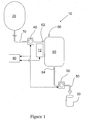
- the present invention provides a fluid dispensing device 10, wherein fluid is feed into and dispensed from a "single-use" pliable fluid reservoir 60 by means of, respectively, a supply-side peristaltic pump 40 and a dispense-side peristaltic pump 50.
- Sensing means 12 are employed to detect the fluid level in the pliable fluid reservoir 50.
- An electronic controller 90 transmits and receives signals to and from the sensing means, and to and from either one of or both peristaltic pumps 40 and 50. Information carried on said signals is processed by the electronic controller 90, and appropriate signals sent to these (and possibly other) device components to thereby control the conduct of fluid dispensation.
- the fluid dispensing device comprises: a pliable fluid reservoir having a fluid inlet and a fluid outlet; a supply-side conduit connected to the fluid inlet; a dispense-side conduit connected to the fluid outlet; sensing means placed proximate the pliable fluid reservoir, said sensing means capable of detecting the fluid level in the pliable fluid reservoir and transmitting data thereabout; a supply-side peristaltic pump engaged onto the supply-side conduit; a dispense-side peristaltic pump engaged onto the dispense-side conduit; and an electronic controller capable of controlling the supply-side and/or the dispense-side peristaltic pumps based on data received from said sensing means.
- the present invention provides a fluid dispensing device 10 that can be used to dispensed fluid from a fluid supply 20 to a receptacle 30.
- the fluid dispensing device includes a pliable fluid reservoir 60 that has a fluid inlet 62 and a fluid outlet 64.
- a "supply-side” conduit 70 and a "dispense-side” conduit are connected, respectively, to the fluid inlet 62 and the fluid outlet 64 of the pliable fluid reservoir 64, with the supply-side conduit being connectable to said fluid supply 20.
- Each of the conduits are engaged or capable of being engaged into respective supply-side and dispense-side peristaltic pumps 40 and 50.
- Sensing means 12 are placed proximate the pliable fluid reservoir 60 to enable detection of the fluid level therein and to transmit or otherwise electronically provide data thereabout.
- An electronic controller 90 is provided to receive said data, and on the basis thereof, control the operation of either one of or both the supply-side and dispense-side peristaltic pumps 40 and 50.
- the pliable fluid reservoir 60 as indicated is provided with at least a fluid inlet 62 and a fluid outlet 64, the fluid inlet and outlet having dimensions, locations, and constructions suitable, for introducing and releasing fluid into and out of the fluid reservoir, respectively.
- the fluid inlet 62 is generally located in the upper half of the pliable fluid reservoir 60, preferably above a predetermined maximum fluid fill level.
- the fluid outlet 64 is generally located in the lower half of the pliable fluid reservoir, preferably in an area that enables optimum and/or essentially complete fluid drainage.
- the pliable fluid reservoir 60 provides functionality comparable to so-called "surge tanks" -- rigid containers often used in industrial fluid dispenser between a larger volume fluid supply container and a dispense head. Regardless, the pliable fluid reservoir 60 also provides fluid pressure control of a character and quality beyond the capacity of rigid surge tanks, while having a construction amenable to single-use disposability.
- the relative size and location of a pliable fluid reservoir 60, when installed into a fluid dispensing device 10, is selected to effect favorably both upstream and downstream fluid pressure conditions, and thereby yield fast and accurate fluid dispensation.
- the pliable fluid reservoir 60 is preferably of substantially unitary construction, having a minimum number of assembled parts, seams, welds, and integrated sub-components.
- the currently preferred reservoir 60 is a bag of durable single-layer construction.
- the "pliability" of the pliable fluid reservoir 60 will vary among different applications, being influenced by such things as the expected external pressure, the rheological properties of the dispensed sample fluid, the configuration and internal volume of any implemented dispense-side conduit manifold assembly, and the like.
- the chemical properties of the fluid will likely influence the type of materials that can be used to make the pliable fluid reservoir, for example, certain fluids may require the use of less pliable, durable materials. Regardless, the balance between durability and pliability is felt within the skill in the art.
- the pliable fluid reservoir 60 is combined in construction with the supply-side conduit 70 and the dispense-side conduit 80, forming a disposable single-use "cartridge" ( cf., a "consumable") that can be easily installed prior to use into the other fixed "hardware" components of the fluid filtration device 10.
- the supply-side conduit 70 is attached to the pliable fluid reservoir 60 at its fluid inlet 62.
- the dispense-side conduit 80 is attached to pliable fluid reservoir 60 at its fluid outlet 64.
- a filter element (not shown) can be integrated into the supply-side conduit at a location either upstream or downstream of the location reserved for the supply-side peristaltic pump 40.
- conduits 70 and 80 there is no particular limitation to the construction of conduits 70 and 80, other than that they be sufficiently pliable, flexible, and/or compressible to allow fluid to be sequentially "squeezed" therethrough by peristaltic pumps 40 and 50.
- both the supply-side and dispense-side conduits 70 and 80 comprise flexible, substantially biologically inert, synthetic polymeric tubing having an internal diameter of approximately .100 inches (0.254 cm). Both conduits 70 and 80 are preferably integral with, fused to, welded to, or otherwise permanently connected to the pliable fluid reservoir 20.
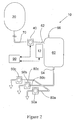
- the fluid dispensing device 10 can employ a manifold assembly 68 to subdivide the dispense-side conduit 80 into a plurality of sub-branches 80a, 80b, and 80c.
- each conduit sub-branch is provided with its own peristaltic pump 50a, 50b, and 50c.
- a single peristaltic pump can be engaged onto dispense-side conduit 80 prior to the branching thereof by the manifold assembly 68, with the control of flow through each sub-branch 80a, 80b, and 80c enabled by the use of electronically-controllable pinch valves (not shown) engaged thereonto.
- the former construction i.e ., multiple pumps
- the discharge end (i.e., "head") of the dispense-side conduit 80 is preferably fitted, for example, with a hermetically-enclosed syringe needle (not shown) to enable aseptic fluid dispensation from the pliable fluid reservoir 60 into, for example, a septum-capped vial or like receptacle.
- suitable polymeric material for the pliable fluid reservoir and the conduits 70 and 80 include, but are not limited to, polycarbonates, polyesters, nylons, PTFE resins and other fluoropolymers, acrylic and methacrylic resins and copolymers, polysulphones, polyethersulphones, polyaryl-sulphones, polystryenes, polyvinyl chlorides, chlorinated polyvinyl chlorides, ABS and its alloys and blends, polyurethanes, thermoset polymers, polyolefins ( e.g. , low density polyethylene, high density polyethylene, and ultrahigh molecular weight polyethylene and copolymers thereof), polypropylene and copolymers thereof, and metallocene generated polyolefins.
- polycarbonates e.g., polycarbonates, polyesters, nylons, PTFE resins and other fluoropolymers, acrylic and methacrylic resins and copolymers, polysulphones, polyethersulphone
- the structure, location, and configuration of the gating means is subject to variation, depending on such factors as, intended application and the structure of the pliable fluid reservoir 60, such as its internal dimensions, and the number of dispense-side conduit heads.
- Two principal embodiments are a vent filter assemblage and a pressure-activated valve. Of these two mechanisms, the vent filter -- in consideration of its potentially lower implementation costs -- is particularly preferred.
- a representative embodiment comprises a structure molded into or installed onto the pliable fluid reservoir 60 above the expected maximum fluid level and that forms thereon an inlet and an outlet, with a passage therebetween, and a membrane or filter cross-sectionally dividing said passage.
- the total internal volume of pliable fluid reservoir 60 as currently embodied is in the range of about 1.5 liters to about 10 liters.
- the dimensions of the supply inlet, optional vent outlet, and fluid output are as follows: The diameter of the supply inlet ranges from about 0.25 inch to about 0.75 inch (about 0.635 cm to about 1.90 cm); the diameter of the vent outlet ranges from about 0.125 inch to about 0.75 inch (about 0.3175 cm to about 1.90 cm); and the diameter of the fluid outlet ranges from about 0.125 inch to about 0.75 inch (about 0.3175 cm to about 0.1.90 cm).
- the diameter of the supply inlet ranges from about 0.25 inch to about 0.75 inch (about 0.635 cm to about 1.90 cm); the diameter of the vent outlet ranges from about 0.125 inch to about 0.75 inch (about 0.3175 cm to about 1.90 cm); and the diameter of the fluid outlet ranges from about 0.125 inch to about 0.75 inch (about 0.3175 cm to about 0.1.90 cm).
- a pair of peristaltic pumps 40 and 50 are engaged onto the supply-side conduit 70 and dispense-side conduit, respectively.
- the supply-side peristaltic pump 40 provides the peristaltic urging force that enables flow of sample liquid from the fluid supply 20 into the pliable fluid reservoir 60.
- the dispense-side peristaltic pump 50 provides the peristaltic urging force that enables flow of sample liquid from the pliable fluid reservoir 60 ultimately out of the fluid dispensing device 10 into an appropriate receptacle 30.
- Both pumps 40 and 50 enable aseptic peristaltic flow and do not require for installation the severing of either conduit. The flow of sample liquid through the conduits remains physically isolated from the outside ambient environment and the pump mechanisms.
- peristaltic pumps 40 and 50 along the conduits 70 and 80 is not categorically critical to the practice of the invention. Although both will likely be placed roughly "midway" positions, other contemplated embodiments of the invention will vary in the location of the pumps 40 and 50. Certain embodiments will benefits in placing the pumps exactly midway of their respective conduits; some embodiments, may locate one (or both) closer to the pliable fluid reservoir; others, farther.
- Factor that may effect pump placement include, but are not limited to, the volume capacity of the fluid supply 20, the volume capacity of the pliable fluid reservoir 60, the length and diameter of the conduits 70 and 80, the viscosity and constituency of targeted sample liquids, the operating range of the selected peristaltic pumps 40 and 50, and/or the desired accuracy and/or dispense rate of the fluid dispensing device 10.
- useful peristaltic pumps will generally comprise, disposed within a housing 42, a channel 52 and peristaltic pinching means 45.
- a conduit 80 (or 70) is engaged within channel 52.
- Peristaltic pinching means 45 is then activated to sequentially pinch the conduit 80 along a length thereof, collapsing the lumen 82 in a wavelike motion, and sequentially displacing sample liquid therein along flow path F.
- Peristaltic pumps are generally one of two types, namely rotary peristaltic pumps and linear peristaltic pumps, illustrated in Figs. 3A and 3B, respectively.
- the peristaltic pinching mean 45 applies force in a sweeping circular or arcuate motion.
- the pinching force is applied by "fingers” of rotating drum that sequentially pinch the conduit 80 against an arcuate channel 52.
- the peristaltic pinching means 45 applies force in a series of linear, punctuated motions.
- the pinching force is applied by a series of linearly reciprocating fingers -- often disposed on a cam shaft -- that orthogonally meet and pinch sequential portions of the conduit 80.
- the supply-side peristaltic pump 40 and dispense-side peristaltic pump 50 can be same or different in respect of type and/or capacity.
- both pumps 40 and 50 are identical.
- a supplemental discharge valve or gate e.g., a pinch valve
- the flow of sample liquid out of the fluid dispensing device into receptacle 30 is variably controlled -- in respect of active and inactive sample flow rate and volume -- exclusively by the dispense-side peristaltic pump 50.
- an appropriately liquid-tight peristaltic pump such configuration facilitates construction, maintenance, and operation, while still providing good fluid dispensation with little to no dripping.
- sensing means 12 are installed or otherwise provided proximate the pliable fluid reservoir 60 to enable the detection of level or volume of fluid contained therein.
- the sensing means can accomplish detection optically, sonically, electronically, or by weight. Fluid volume detection through such avenues are known, and can be incorporated as desired.
- Fig. 4 and Fig. 5 provide representative schematic embodiments of an optical and an electronic sensing means, respectively.
- the optical sensing means is configured to comprise: a side tube 16 connected to and in "fluid communication" with the pliable fluid reservoir 60; and a plurality of optical detectors 14 T and 14 B located to detect attainment of certain user-definable top and bottom fluid levels, respectively, along said side tube 16.
- the optical detectors 14 T and 14 B provide electronic signal indicative of the water level in the side tube 16, which correlate with the fluid level in the pliable fluid reservoir 60.
- the volume of fluid in the pliable fluid reservoir 60 is a key consideration in practicing the present invention, and in particular, the operation of the peristaltic pumps 40 and 50. Larger fluid volumes in the reservoir 60 require correspondingly greater pumping forces to be applied by the supply-side peristaltic pump 40 to pump fluid thereinto. Likewise, larger volumes of fluid will apply correspondingly greater fluid pressures downstream upon the dispense-side peristaltic pump 50.
- a typical optical detector will generally comprise a light source and a light receiver, either combined within a single unit or paired and assembled in close proximity.
- the light source supplies an optical signal (e.g. a beam or pulse or fan of collimated or coherent light) that is propagated along an optical pathway -- linear or otherwise -- that terminates at said light receiver after incidence upon said side tube 16.
- the light receiver is provided with a photoreceptor (e.g. , a charge-coupled device) that provides an electronic signal corresponding with and in response to the light impinging thereon.
- the fluid level in the pliable fluid reservoir 60 can also be monitored using -- instead of optical fluid level sensors 52 and 54 -- electronic sensing mean.
- the electronic fluid level sensing means can be used to measure reservoir fluid levels directly from pliable fluid reservoir 60 or indirectly from a side tube 16.
- electroconductive terminals 18 e.g. , thin strip of conductive metal
- An electric current is passed from one terminal to another, and capacitance or resistance or the like is measured and a signal produced. Variations in capacitance or resistance can be correlated with variations in fluid level.
- the electroconductive terminals by themselves are not sufficient to render operable the electronic fluid level sensing means.
- the electroconductive terminals need to be wired or otherwise linked or connected to both an energy source and an electronic control mechanism, both of which can be integrated within a single sub-component.
- the energy source essentially drives a current through both terminals, whilst the electronic control mechanism -- for example, by incorporation therein of a potentiometer or like electronic sensor -- measures the capacitance of said current and, based thereon, selectively opens and/or closes the relevant valves and/or pumps.
- a consumable embodiment of the pliable fluid reservoir 60 can include the terminals, and perhaps some leads and wires, that are plugged into and/or otherwise connected to appropriate dedicated sockets into the non-disposable hardware components of the fluid filtration device 10.
- the electronic terminals comprise two narrow copper strips mounted permanently to the side wall of the side tube 16.
- the strips are mounted opposed to one another on the outside of the tube and traverse its entire "working" length. Capacitance detection is accomplished by passing a pulsed current across the space between the two metal strips. The capacitance of the material separating the strips is measured. Since there is a significant difference between the capacitance of an empty air-filled tube and one that is liquid filled, the liquid volume can be continually monitored as it move up and down the side tube.
- the copper strips can be mounted as follows: One is mounted on the outside of the side tube (e.g., towards a bottom portion thereof) and the second is placed inside the tube assembly suspended without touching the walls. This embodiment is particularly appropriate for high viscosity fluids that tend to "cling" vigorously to the tube's side walls.
- the internally mounted terminal is preferably coated with a chemically non-reactive polymeric material or otherwise protected or isolated with some other suitable barrier.
- the capacitance in the fill tube assembly is measured continuously, so that the volume of in the tube will be continuously determined, rather than determining certain minimum and maximum volumes. Since the capacitance sensor measures the liquid continuously, so-called “proportional-integral-derivative” (PID) control of the system, rather than only proportional control, can be used thus improving the dispense accuracy and the repeatability.
- PID proportional-integral-derivative
- an electronic controller 90 is used to control the operation of the supply-side peristaltic pump 40 and/or the dispense-side peristaltic pump 50 based, at least in part, directly or indirectly, on the data (i.e., the signals) provided by the fluid level sensing mean 12.
- the electronic controller 90 controls exclusively the operation of the supply-side peristaltic pump 40 based on data provided by the fluid level sensing means 12.
- both pumps 40 and 50 are controlled by the electronic controller 90.
- the electronic controller 90 should be capable of receiving, processing, and providing data at least to and from the sensing means 12 and either or both the peristaltic pumps 40 and 50. Similar functionality can be also provided for other potential device components, such as pinch valves, agitators, thermal sensors, data recording and printing devices, system displays, and the like.
- the electronic controller 90 can comprise circuitry, wiring, memory modules, a power supply, input and output ports, a user interface, processors and coprocessors, and other well-known electronic components to effect electronic connectivity and control of the serviced device components.
- the electronic controller can comprise either single centralized electronic package (e.g. , a dedicated notebook computer or a multi-functional printed circuit board) or a network of distributed sub-components (e.g. , a plurality of separate component-specific PCBs) wired or otherwise networked to a separate central processing unit.
- a particular example of a distributed electronic controller system include a computer linked to an industrial programmable logic controller (i.e ., a "PLC"), the programmable logic controller itself being linked to the electronically-controlled sensors and pumps.
- a programmable logic controller is essentially a device-specific computer board or component capable of electronically receiving, processing, and transmitting electronic data.
- the programmable logic controller operates with "raw" data and has embedded operating software therefor.
- the computer can be configured to communicate with, and to some extent control, the programmable logic controller, with higher level operations carried out by computer.
- Use of a programmable logic controller affords advantage in respect of easier replacement or substitution of a central device computer, as well as enabling broader variability in its selection.
Landscapes
- Engineering & Computer Science (AREA)
- Mechanical Engineering (AREA)
- Physics & Mathematics (AREA)
- Fluid Mechanics (AREA)
- General Physics & Mathematics (AREA)
- General Engineering & Computer Science (AREA)
- Reciprocating Pumps (AREA)
- Devices For Dispensing Beverages (AREA)
- Basic Packing Technique (AREA)
- Loading And Unloading Of Fuel Tanks Or Ships (AREA)
Applications Claiming Priority (2)
| Application Number | Priority Date | Filing Date | Title |
|---|---|---|---|
| US523625 | 2000-03-13 | ||
| US52362503P | 2003-11-20 | 2003-11-20 |
Publications (1)
| Publication Number | Publication Date |
|---|---|
| EP1533597A1 true EP1533597A1 (en) | 2005-05-25 |
Family
ID=34435220
Family Applications (1)
| Application Number | Title | Priority Date | Filing Date |
|---|---|---|---|
| EP04027126A Withdrawn EP1533597A1 (en) | 2003-11-20 | 2004-11-15 | Fluid dispensing device |
Country Status (3)
| Country | Link |
|---|---|
| US (1) | US7896197B2 (enExample) |
| EP (1) | EP1533597A1 (enExample) |
| JP (2) | JP4518918B2 (enExample) |
Cited By (15)
| Publication number | Priority date | Publication date | Assignee | Title |
|---|---|---|---|---|
| US7924424B2 (en) | 2007-10-11 | 2011-04-12 | Ecolab Usa Inc. | Optical product detection sensor |
| US8004683B2 (en) | 2007-10-11 | 2011-08-23 | Ecolab Usa Inc. | Optical product detection sensor |
| NL2008648C2 (nl) * | 2012-04-17 | 2013-10-21 | Nyc Be Beautiful B V | Saus doseerinrichting. |
| CN104386386A (zh) * | 2014-11-07 | 2015-03-04 | 广德瑞邦涂料有限公司 | 一种用于生产阴极水溶性电泳漆乳液的计量装置 |
| WO2015136166A1 (fr) * | 2014-03-14 | 2015-09-17 | 1/4 Vin | Procede et dispositif de conditionnement de boisson |
| KR20200103840A (ko) * | 2011-12-22 | 2020-09-02 | 아이씨유 메디칼 인코퍼레이티드 | 의료용 유체 전달 시스템, 유체 전달 방법, 전자 의료용 유체 전달 시스템, 및 전자 의료용 유체 전달 시스템 이용 방법 |
| US11007119B2 (en) | 2009-07-29 | 2021-05-18 | Icu Medical, Inc. | Fluid transfer devices and methods of use |
| US11135416B2 (en) | 2015-12-04 | 2021-10-05 | Icu Medical, Inc. | Systems, methods, and components for transferring medical fluids |
| USD943732S1 (en) | 2016-07-19 | 2022-02-15 | Icu Medical, Inc. | Medical fluid transfer system |
| US11541171B2 (en) | 2013-11-25 | 2023-01-03 | Icu Medical, Inc. | Methods and systems for filling IV bags with therapeutic fluid |
| US11583637B2 (en) | 2016-07-25 | 2023-02-21 | Icu Medical, Inc. | Systems, methods, and components for trapping air bubbles in medical fluid transfer modules and systems |
| US11590057B2 (en) | 2020-04-03 | 2023-02-28 | Icu Medical, Inc. | Systems, methods, and components for transferring medical fluids |
| GB2611042A (en) * | 2021-09-22 | 2023-03-29 | Trewithen Dairy | Milk-based products and dispensers |
| LU506763B1 (de) * | 2024-04-02 | 2025-10-03 | Larkwick Gmbh | Zusatzeinheit für eine Dispensiervorrichtung |
| WO2025210025A1 (de) * | 2024-04-02 | 2025-10-09 | Larkwick Gmbh | Zusatzeinheit für eine dispensiervorrichtung |
Families Citing this family (42)
| Publication number | Priority date | Publication date | Assignee | Title |
|---|---|---|---|---|
| US6712963B2 (en) * | 2002-06-14 | 2004-03-30 | Scilog, Llc | Single-use manifold for automated, aseptic transfer of solutions in bioprocessing applications |
| US9283521B2 (en) | 2002-06-14 | 2016-03-15 | Parker-Hannifin Corporation | Single-use manifold and sensors for automated, aseptic transfer of solutions in bioprocessing applications |
| USRE49221E1 (en) | 2002-06-14 | 2022-09-27 | Parker Intangibles, Llc | Single-use manifolds for automated, aseptic handling of solutions in bioprocessing applications |
| WO2008042427A2 (en) * | 2006-10-03 | 2008-04-10 | Rochester Midland Corporation | Automatic dispenser |
| WO2008131186A1 (en) * | 2007-04-18 | 2008-10-30 | Becton, Dickinson And Company | Method and apparatus for determining dispense volume |
| DE102007040323B4 (de) * | 2007-08-24 | 2015-12-17 | Henkel Ag & Co. Kgaa | WC-Spüler mit einstellbarer Wirkstoffabgabemenge |
| DE102008015387B4 (de) * | 2008-03-20 | 2019-01-10 | Sartorius Stedim Biotech Gmbh | Vorsterilisierbares Filtrationssystem zum Einmalgebrauch |
| WO2011124388A1 (de) * | 2010-04-09 | 2011-10-13 | Gesundheitsmanager Gmbh | Absaugsystem zum absaugen einer körperflüssigkeit |
| DE102010060469B3 (de) * | 2010-11-10 | 2011-11-10 | Sartorius Ag | Behälteranordnung und Verfahren zum Füllen von flexiblen Einwegbeuteln |
| CN104619368B (zh) * | 2012-07-31 | 2018-11-30 | 三伟达保健系统有限责任公司 | 用于从输液泵分配流体的装置和方法 |
| WO2014029740A1 (de) * | 2012-08-20 | 2014-02-27 | Washtec Holding Gmbh | Dosiervorrichtung und verfahren zur dosierung von zusatzmitteln in behandlungsflüssigkeiten einer fahrzeugbehandlungsanlage |
| PL2969109T3 (pl) * | 2013-03-15 | 2020-03-31 | Davco Technology, L.L.C. | Automatyczny odpływ dla procesora paliwowego |
| GB201305755D0 (en) | 2013-03-28 | 2013-05-15 | Quanta Fluid Solutions Ltd | Re-Use of a Hemodialysis Cartridge |
| GB201314512D0 (en) | 2013-08-14 | 2013-09-25 | Quanta Fluid Solutions Ltd | Dual Haemodialysis and Haemodiafiltration blood treatment device |
| GB201409796D0 (en) | 2014-06-02 | 2014-07-16 | Quanta Fluid Solutions Ltd | Method of heat sanitization of a haemodialysis water circuit using a calculated dose |
| EP3166393B1 (en) * | 2014-07-07 | 2018-08-29 | Tetra Laval Holdings & Finance S.A. | Optimization of a filling line |
| EP3393964B1 (en) * | 2015-12-21 | 2020-03-11 | Tetra Laval Holdings & Finance S.A. | Product loss reduction by using shortened purge for aseptic tank |
| GB201523104D0 (en) | 2015-12-30 | 2016-02-10 | Quanta Fluid Solutions Ltd | Dialysis machine |
| GB2547214A (en) | 2016-02-10 | 2017-08-16 | Quanta Fluid Solutions Ltd | Membrane pump usage condition detection |
| JP2018065577A (ja) * | 2016-10-17 | 2018-04-26 | シブヤパッケージングシステム株式会社 | 充填装置 |
| GB201622119D0 (en) | 2016-12-23 | 2017-02-08 | Quanta Dialysis Tech Ltd | Improved valve leak detection system |
| GB201701740D0 (en) | 2017-02-02 | 2017-03-22 | Quanta Dialysis Tech Ltd | Phased convective operation |
| GB201703048D0 (en) * | 2017-02-24 | 2017-04-12 | Quanta Dialysis Tech Ltd | Testing rotor engagement of a rotary peristaltic pump |
| GB201705273D0 (en) | 2017-03-31 | 2017-05-17 | Quanta Dialysis Tech Ltd | Data storage amd exchange by medical device components |
| GB201710546D0 (en) | 2017-06-30 | 2017-08-16 | Quanta Dialysis Tech Ltd | Dialysis systems, devices and methods |
| JP2019055795A (ja) * | 2017-09-20 | 2019-04-11 | 株式会社進洋 | 充填製袋機 |
| USD907211S1 (en) | 2017-09-28 | 2021-01-05 | Quanta Dialysis Technologies Ltd. | Dialysis machine |
| EP3749387A4 (en) | 2018-02-11 | 2021-11-10 | Eitan Medical Ltd. | FLEXIBLE STROKE INFUSION PUMP |
| GB2572402B (en) * | 2018-03-29 | 2020-06-17 | Hodges & Drake Design Ltd | A pumping apparatus with first and second peristaltic pumps |
| US11191897B2 (en) | 2019-03-04 | 2021-12-07 | Eitan Medical Ltd. | In cycle pressure measurement |
| US12318576B2 (en) | 2019-03-05 | 2025-06-03 | Eitan Medical Ltd. | Infusion pump with toggling capability |
| US12186528B2 (en) | 2019-03-05 | 2025-01-07 | Eitan Medical Ltd. | Infusion pump cassette latch |
| WO2020178827A1 (en) | 2019-03-05 | 2020-09-10 | Avoset Health Ltd. | Anti-free-flow valve |
| US12214162B2 (en) | 2019-03-05 | 2025-02-04 | Eitan Medical Ltd. | Infusion pump with valve compensation |
| GB2584335A (en) | 2019-05-31 | 2020-12-02 | Quanta Dialysis Technologies Ltd | Source container connector |
| TWI895352B (zh) * | 2020-02-14 | 2025-09-01 | 瑞士商赫孚孟拉羅股份公司 | 用於液體藥物產物之時間-壓力-充填系統與方法以及其用途 |
| WO2022132544A1 (en) * | 2020-12-14 | 2022-06-23 | Merck Sharp & Dohme Corp. | Aseptic manifold dispensing assembly |
| US11897754B2 (en) * | 2021-03-26 | 2024-02-13 | Henkel Ag & Co. Kgaa | Dispensing system with liquid level sensing and level-based actions |
| CN113734486A (zh) * | 2021-09-10 | 2021-12-03 | 杭州穆恩自动化科技有限公司 | 一种联动线的灌装结构及灌装搅拌方法 |
| US20250213430A1 (en) * | 2022-03-14 | 2025-07-03 | Amgen Inc. | Automated drug filling process |
| WO2023239635A1 (en) * | 2022-06-05 | 2023-12-14 | Wonderfil, Pbc | Devices, systems, and methods for dispensing fluid products |
| CN115583370A (zh) * | 2022-09-19 | 2023-01-10 | 深圳赛桥生物创新技术有限公司 | 生物制剂定量分装装置及分装方法 |
Citations (5)
| Publication number | Priority date | Publication date | Assignee | Title |
|---|---|---|---|---|
| EP0058292A2 (en) * | 1981-01-29 | 1982-08-25 | SOXIL S.p.A. GRUPPO PIERREL | Apparatus for dispensing a predetermined quantity of a substantially liquid product for therapeutic use in a presettable time |
| US4528158A (en) * | 1982-06-14 | 1985-07-09 | Baird Corporation | Automatic sampling system |
| US6202708B1 (en) | 1998-11-09 | 2001-03-20 | Sims Deltec, Inc. | Fillable cassette apparatus and method |
| EP1145727A1 (de) * | 2000-04-12 | 2001-10-17 | European Aesthetics GmbH | Pumpe zum sterilen Fördern erwärmter Tumeszenzlösung |
| US20020092559A1 (en) | 2000-02-18 | 2002-07-18 | Tokyo Electron Limited | Treatment solution supply method and treatment solution supply unit |
Family Cites Families (30)
| Publication number | Priority date | Publication date | Assignee | Title |
|---|---|---|---|---|
| US2412397A (en) | 1943-12-31 | 1946-12-10 | Lyndus E Harper | Flexible tube pump |
| US2909125A (en) | 1956-01-16 | 1959-10-20 | Paul J Daniels | Liquid dispensers |
| JPS4528507Y1 (enExample) * | 1966-09-09 | 1970-11-04 | ||
| US4030640A (en) * | 1975-11-10 | 1977-06-21 | Indicon Inc. | Method and apparatus for dispensing viscous materials |
| DE2754894C2 (de) * | 1977-12-09 | 1983-10-13 | Fresenius AG, 6380 Bad Homburg | Vorrichtung zum Bilanzieren einer einem Patienten entnommenen Flüssigkeit mit einer Ersatzflüssigkeit |
| DE2755214C3 (de) * | 1977-12-10 | 1980-12-11 | Dr. Eduard Fresenius Chemisch-Pharmazeutische Industrie Kg Apparatebau Kg, 6380 Bad Homburg | Vorrichtung zur periodischen Spülung der Bauchhöhle |
| JPS5980300U (ja) * | 1982-11-19 | 1984-05-30 | 三洋電機株式会社 | 糖分を含有する飲料供給装置 |
| JPS62188500U (enExample) * | 1986-05-20 | 1987-12-01 | ||
| US4712590A (en) * | 1986-05-30 | 1987-12-15 | Baxter Travenol Laboratories, Inc. | Electrical connection means for multiple bulk compounding systems |
| JPH02109895A (ja) * | 1988-10-13 | 1990-04-23 | Tokyo Koka Cola Botoringu Kk | 飲食物の供給装置 |
| US5165873A (en) | 1989-10-10 | 1992-11-24 | Imed Corporation | Two-cycle peristaltic pump |
| FI85563C (fi) * | 1990-08-08 | 1992-05-11 | Cimcorp Oy | Faergnyanseringsmaskin. |
| US5234608A (en) * | 1990-12-11 | 1993-08-10 | Baxter International Inc. | Systems and methods for processing cellular rich suspensions |
| US5090594A (en) | 1991-01-15 | 1992-02-25 | Flowclean Equipment, Inc. | Volumetric fluid dispensing apparatus and method |
| JP2542518Y2 (ja) | 1991-05-29 | 1997-07-30 | 四国化工機株式会社 | 液体定圧供給装置 |
| US5698090A (en) * | 1991-09-10 | 1997-12-16 | Hospal Industrie | Artificial kidney for adjusting a concentration of substance in blood |
| JP2972970B2 (ja) * | 1992-04-24 | 1999-11-08 | 東京エレクトロン株式会社 | 処理装置 |
| US5480063A (en) | 1993-03-05 | 1996-01-02 | Keyes; Denis E. | Volumetric fluid dispensing apparatus |
| US5680960A (en) | 1993-03-05 | 1997-10-28 | Keyes; Denis E. | Volumetric fluid dispensing apparatus |
| GB2285837B (en) | 1994-01-24 | 1998-05-13 | Varian Australia | Peristaltic pump |
| FR2737261B1 (fr) | 1995-07-27 | 1997-10-10 | Jean Francois Ognier | Pompe peristaltique |
| US5697407A (en) * | 1995-11-30 | 1997-12-16 | The Metrix Company | Compounding system for multiple chamber receptacles |
| JPH09309594A (ja) * | 1996-05-24 | 1997-12-02 | Chichibu Fuji:Kk | 飲食物供給装置 |
| US5664990A (en) * | 1996-07-29 | 1997-09-09 | Integrated Process Equipment Corp. | Slurry recycling in CMP apparatus |
| DE19640664C1 (de) * | 1996-10-02 | 1998-02-05 | Bosch Gmbh Robert | Vorrichtung zum Abfüllen einer unter Druck stehenden Flüssigkeit |
| GR1002892B (el) | 1997-02-17 | 1998-04-10 | Micrel | Γραμμικη περισταλτικη αντλια |
| US6036166A (en) * | 1997-09-25 | 2000-03-14 | Imi Cornelius Inc. | Chamber valve |
| US6673594B1 (en) * | 1998-09-29 | 2004-01-06 | Organ Recovery Systems | Apparatus and method for maintaining and/or restoring viability of organs |
| EP1620347A4 (en) * | 2003-02-24 | 2007-08-29 | Millipore Corp | FLUID DISPENSER WITH MEANS FOR CONTINUOUS MEASUREMENT OF FLUID VOLUMES |
| US7128242B2 (en) * | 2003-09-15 | 2006-10-31 | Erlandsen David H | Storage and dispensing aliquot portions of liquid egg in a wholesome and convenient manner |
-
2004
- 2004-11-15 EP EP04027126A patent/EP1533597A1/en not_active Withdrawn
- 2004-11-15 JP JP2004330074A patent/JP4518918B2/ja not_active Expired - Fee Related
- 2004-11-19 US US10/992,877 patent/US7896197B2/en not_active Expired - Fee Related
-
2009
- 2009-07-08 JP JP2009161376A patent/JP2009234664A/ja not_active Withdrawn
Patent Citations (5)
| Publication number | Priority date | Publication date | Assignee | Title |
|---|---|---|---|---|
| EP0058292A2 (en) * | 1981-01-29 | 1982-08-25 | SOXIL S.p.A. GRUPPO PIERREL | Apparatus for dispensing a predetermined quantity of a substantially liquid product for therapeutic use in a presettable time |
| US4528158A (en) * | 1982-06-14 | 1985-07-09 | Baird Corporation | Automatic sampling system |
| US6202708B1 (en) | 1998-11-09 | 2001-03-20 | Sims Deltec, Inc. | Fillable cassette apparatus and method |
| US20020092559A1 (en) | 2000-02-18 | 2002-07-18 | Tokyo Electron Limited | Treatment solution supply method and treatment solution supply unit |
| EP1145727A1 (de) * | 2000-04-12 | 2001-10-17 | European Aesthetics GmbH | Pumpe zum sterilen Fördern erwärmter Tumeszenzlösung |
Cited By (30)
| Publication number | Priority date | Publication date | Assignee | Title |
|---|---|---|---|---|
| US8004683B2 (en) | 2007-10-11 | 2011-08-23 | Ecolab Usa Inc. | Optical product detection sensor |
| US7924424B2 (en) | 2007-10-11 | 2011-04-12 | Ecolab Usa Inc. | Optical product detection sensor |
| US12186270B2 (en) | 2009-07-29 | 2025-01-07 | Icu Medical, Inc. | Fluid transfer devices and methods of use |
| US11806308B2 (en) | 2009-07-29 | 2023-11-07 | Icu Medical, Inc. | Fluid transfer devices and methods of use |
| US11007119B2 (en) | 2009-07-29 | 2021-05-18 | Icu Medical, Inc. | Fluid transfer devices and methods of use |
| US11439570B2 (en) | 2011-12-22 | 2022-09-13 | Icu Medical, Inc. | Fluid transfer devices and methods of use |
| US12023304B2 (en) | 2011-12-22 | 2024-07-02 | Icu Medical, Inc. | Fluid transfer devices and methods of use |
| KR20200103840A (ko) * | 2011-12-22 | 2020-09-02 | 아이씨유 메디칼 인코퍼레이티드 | 의료용 유체 전달 시스템, 유체 전달 방법, 전자 의료용 유체 전달 시스템, 및 전자 의료용 유체 전달 시스템 이용 방법 |
| US11439571B2 (en) | 2011-12-22 | 2022-09-13 | Icu Medical, Inc. | Fluid transfer devices and methods of use |
| NL2008648C2 (nl) * | 2012-04-17 | 2013-10-21 | Nyc Be Beautiful B V | Saus doseerinrichting. |
| WO2013157939A1 (en) * | 2012-04-17 | 2013-10-24 | Nyc Be Beautiful B.V. | Sauce dispensing device |
| US11541171B2 (en) | 2013-11-25 | 2023-01-03 | Icu Medical, Inc. | Methods and systems for filling IV bags with therapeutic fluid |
| FR3018513A1 (fr) * | 2014-03-14 | 2015-09-18 | 1 4 Vin | Procede et dispositif de conditionnement de boisson |
| WO2015136166A1 (fr) * | 2014-03-14 | 2015-09-17 | 1/4 Vin | Procede et dispositif de conditionnement de boisson |
| CN104386386A (zh) * | 2014-11-07 | 2015-03-04 | 广德瑞邦涂料有限公司 | 一种用于生产阴极水溶性电泳漆乳液的计量装置 |
| USD1018849S1 (en) | 2015-12-04 | 2024-03-19 | Icu Medical, Inc. | Fluid transfer device |
| USD948044S1 (en) | 2015-12-04 | 2022-04-05 | Icu Medical, Inc. | Fluid transfer device |
| US11135416B2 (en) | 2015-12-04 | 2021-10-05 | Icu Medical, Inc. | Systems, methods, and components for transferring medical fluids |
| US11865295B2 (en) | 2015-12-04 | 2024-01-09 | Icu Medical, Inc. | Systems, methods, and components for transferring medical fluids |
| USD943732S1 (en) | 2016-07-19 | 2022-02-15 | Icu Medical, Inc. | Medical fluid transfer system |
| US11951293B2 (en) | 2016-07-25 | 2024-04-09 | Icu Medical, Inc. | Systems, methods, and components for trapping air bubbles in medical fluid transfer modules and systems |
| US11583637B2 (en) | 2016-07-25 | 2023-02-21 | Icu Medical, Inc. | Systems, methods, and components for trapping air bubbles in medical fluid transfer modules and systems |
| US12280249B2 (en) | 2016-07-25 | 2025-04-22 | Icu Medical, Inc. | Systems, methods, and components for trapping air bubbles in medical fluid transfer modules and systems |
| US11590057B2 (en) | 2020-04-03 | 2023-02-28 | Icu Medical, Inc. | Systems, methods, and components for transferring medical fluids |
| US12303464B2 (en) | 2020-04-03 | 2025-05-20 | Icu Medical, Inc. | Systems, methods, and components for transferring medical fluids |
| GB2611042B (en) * | 2021-09-22 | 2024-03-27 | Trewithen Dairy | System for dispensing pumpable liquid foodstuff |
| GB2611042A (en) * | 2021-09-22 | 2023-03-29 | Trewithen Dairy | Milk-based products and dispensers |
| LU506763B1 (de) * | 2024-04-02 | 2025-10-03 | Larkwick Gmbh | Zusatzeinheit für eine Dispensiervorrichtung |
| WO2025209671A1 (de) * | 2024-04-02 | 2025-10-09 | Larkwick Gmbh | Zusatzeinheit für eine dispensiervorrichtung |
| WO2025210025A1 (de) * | 2024-04-02 | 2025-10-09 | Larkwick Gmbh | Zusatzeinheit für eine dispensiervorrichtung |
Also Published As
| Publication number | Publication date |
|---|---|
| JP4518918B2 (ja) | 2010-08-04 |
| JP2005154008A (ja) | 2005-06-16 |
| JP2009234664A (ja) | 2009-10-15 |
| US7896197B2 (en) | 2011-03-01 |
| US20050109795A1 (en) | 2005-05-26 |
Similar Documents
| Publication | Publication Date | Title |
|---|---|---|
| US7896197B2 (en) | Fluid dispensing device | |
| EP1808381B1 (en) | Fluid dispensing system with pouch-reservoir | |
| EP3074751B1 (en) | Fluidics system for flow cytometer | |
| US8118191B2 (en) | Liquid dispensing system with enhanced mixing | |
| US7104422B2 (en) | Fluid dispensing apparatus having means for measuring fluid volume continuously | |
| US20070243106A1 (en) | Flow cytometer system with sheath and waste fluid measurement | |
| WO2012064809A1 (en) | Real time measurements of fluid volume and flow rate using two pressure transducers | |
| WO2012126745A2 (en) | Methods and devices for operating an infusion system | |
| CN102865205A (zh) | 连续送液系统及其控制方法 | |
| JP7448286B2 (ja) | バイオプロセスシステムのためのバッファ管理 | |
| CN104321626A (zh) | 乳制品液位测量装置和相关的测量方法 | |
| EP3933193B1 (en) | Liquid supply system | |
| US20050269368A1 (en) | Fluid dispenser cartridge with bladder means | |
| US7228992B2 (en) | Fluid dispenser cartridge | |
| US7118011B2 (en) | Fluid dispensing apparatus | |
| US20100175774A1 (en) | Device and method for metering media | |
| US7367473B2 (en) | Circuit for dispensing fluid products, in particular colouring agents, paints or similar fluid products | |
| KR0166169B1 (ko) | 액상내용물의 충진장치 | |
| JPS6336067A (ja) | 定圧保持装置 |
Legal Events
| Date | Code | Title | Description |
|---|---|---|---|
| PUAI | Public reference made under article 153(3) epc to a published international application that has entered the european phase |
Free format text: ORIGINAL CODE: 0009012 |
|
| AK | Designated contracting states |
Kind code of ref document: A1 Designated state(s): AT BE BG CH CY CZ DE DK EE ES FI FR GB GR HU IE IS IT LI LU MC NL PL PT RO SE SI SK TR |
|
| AX | Request for extension of the european patent |
Extension state: AL HR LT LV MK YU |
|
| 17P | Request for examination filed |
Effective date: 20051108 |
|
| AKX | Designation fees paid |
Designated state(s): AT BE BG CH CY CZ DE DK EE ES FI FR GB GR HU IE IS IT LI LU MC NL PL PT RO SE SI SK TR |
|
| 17Q | First examination report despatched |
Effective date: 20111004 |
|
| RAP1 | Party data changed (applicant data changed or rights of an application transferred) |
Owner name: EMD MILLIPORE CORPORATION |
|
| STAA | Information on the status of an ep patent application or granted ep patent |
Free format text: STATUS: THE APPLICATION IS DEEMED TO BE WITHDRAWN |
|
| 18D | Application deemed to be withdrawn |
Effective date: 20150602 |