EP1533582A1 - Kaltkopf und Observationsvorrichtung mit solchem Gerät - Google Patents
Kaltkopf und Observationsvorrichtung mit solchem Gerät Download PDFInfo
- Publication number
- EP1533582A1 EP1533582A1 EP04292739A EP04292739A EP1533582A1 EP 1533582 A1 EP1533582 A1 EP 1533582A1 EP 04292739 A EP04292739 A EP 04292739A EP 04292739 A EP04292739 A EP 04292739A EP 1533582 A1 EP1533582 A1 EP 1533582A1
- Authority
- EP
- European Patent Office
- Prior art keywords
- finger
- fin
- detector
- finger according
- deformation
- Prior art date
- Legal status (The legal status is an assumption and is not a legal conclusion. Google has not performed a legal analysis and makes no representation as to the accuracy of the status listed.)
- Granted
Links
- 230000002787 reinforcement Effects 0.000 claims abstract description 12
- 239000000463 material Substances 0.000 claims description 7
- 238000009826 distribution Methods 0.000 claims description 3
- 238000001816 cooling Methods 0.000 description 7
- 125000004122 cyclic group Chemical group 0.000 description 6
- 238000004519 manufacturing process Methods 0.000 description 4
- 239000011149 active material Substances 0.000 description 3
- 239000012530 fluid Substances 0.000 description 3
- 230000003014 reinforcing effect Effects 0.000 description 3
- 238000005259 measurement Methods 0.000 description 2
- 230000005855 radiation Effects 0.000 description 2
- 230000003068 static effect Effects 0.000 description 2
- 239000000758 substrate Substances 0.000 description 2
- 229910000831 Steel Inorganic materials 0.000 description 1
- 229910001069 Ti alloy Inorganic materials 0.000 description 1
- 239000012809 cooling fluid Substances 0.000 description 1
- 230000002596 correlated effect Effects 0.000 description 1
- 230000008878 coupling Effects 0.000 description 1
- 238000010168 coupling process Methods 0.000 description 1
- 238000005859 coupling reaction Methods 0.000 description 1
- 230000003247 decreasing effect Effects 0.000 description 1
- 230000001419 dependent effect Effects 0.000 description 1
- 230000000694 effects Effects 0.000 description 1
- 230000004907 flux Effects 0.000 description 1
- 238000003384 imaging method Methods 0.000 description 1
- 239000007788 liquid Substances 0.000 description 1
- 238000003754 machining Methods 0.000 description 1
- 229910052751 metal Inorganic materials 0.000 description 1
- 239000002184 metal Substances 0.000 description 1
- 238000000034 method Methods 0.000 description 1
- 230000010355 oscillation Effects 0.000 description 1
- 238000005057 refrigeration Methods 0.000 description 1
- 239000010959 steel Substances 0.000 description 1
- 239000003351 stiffener Substances 0.000 description 1
- 238000011144 upstream manufacturing Methods 0.000 description 1
Images


Classifications
-
- F—MECHANICAL ENGINEERING; LIGHTING; HEATING; WEAPONS; BLASTING
- F25—REFRIGERATION OR COOLING; COMBINED HEATING AND REFRIGERATION SYSTEMS; HEAT PUMP SYSTEMS; MANUFACTURE OR STORAGE OF ICE; LIQUEFACTION SOLIDIFICATION OF GASES
- F25D—REFRIGERATORS; COLD ROOMS; ICE-BOXES; COOLING OR FREEZING APPARATUS NOT OTHERWISE PROVIDED FOR
- F25D19/00—Arrangement or mounting of refrigeration units with respect to devices or objects to be refrigerated, e.g. infrared detectors
- F25D19/006—Thermal coupling structure or interface
-
- G—PHYSICS
- G01—MEASURING; TESTING
- G01J—MEASUREMENT OF INTENSITY, VELOCITY, SPECTRAL CONTENT, POLARISATION, PHASE OR PULSE CHARACTERISTICS OF INFRARED, VISIBLE OR ULTRAVIOLET LIGHT; COLORIMETRY; RADIATION PYROMETRY
- G01J5/00—Radiation pyrometry, e.g. infrared or optical thermometry
- G01J5/02—Constructional details
- G01J5/06—Arrangements for eliminating effects of disturbing radiation; Arrangements for compensating changes in sensitivity
- G01J5/061—Arrangements for eliminating effects of disturbing radiation; Arrangements for compensating changes in sensitivity by controlling the temperature of the apparatus or parts thereof, e.g. using cooling means or thermostats
-
- H—ELECTRICITY
- H10—SEMICONDUCTOR DEVICES; ELECTRIC SOLID-STATE DEVICES NOT OTHERWISE PROVIDED FOR
- H10F—INORGANIC SEMICONDUCTOR DEVICES SENSITIVE TO INFRARED RADIATION, LIGHT, ELECTROMAGNETIC RADIATION OF SHORTER WAVELENGTH OR CORPUSCULAR RADIATION
- H10F77/00—Constructional details of devices covered by this subclass
- H10F77/60—Arrangements for cooling, heating, ventilating or compensating for temperature fluctuations
Definitions
- the invention relates to a cold finger forming a cooling support of a infrared detector and an observation device comprising such finger.
- FIG. 1 schematically represents a known observation device in the infrared domain.
- Such a device mainly comprises a hollow part 1 and elongate shape, preferably cylindrical of revolution, called "finger by the person skilled in the art, forming an interface between on the one hand a infrared detector 2 in active material and secondly a cryogenerator 3 to bring the detector 2 to its operating temperature and to maintain it at this temperature.
- a cooling fluid from the cryogenerator 3 circulates inside 4 finger 1 and continuously cools the 2.
- the cryogenerator 3 can be of several types.
- the inside 4 of the finger 1 comprises a heat exchanger.
- the cold finger 1 is a source of microphony of by coupling it creates between the detector 2 and the cryogenerator 3.
- microphonie all the response phenomena of the detector 2 to something other than the flow of photons in the infrared range that disturb the measurement of the detector.
- the walls of the finger 1 must be as thin as possible.
- the walls 5 have a thickness of about 0.1 mm. There are two main reasons for this fineness of the walls.
- thin walls avoid energy expenditure too much refrigeration from the cryogenerator 3, because they are brought to the operating temperature of the detector more quickly.
- FIG. 2 shows that the thin walls do not not prevent the finger 1 from being deformed during its operation, the deformation substantially taking the form of a "Barrel" by a curvature 60 of the end 6 and a curvature 70 of ratings 7.
- FIG. 3 shows that in the case of a cyclic cryogenator 3, the deformation due to the pressure prevailing inside the cold finger 1 is of the same order of magnitude as the deformation in the case of an expansion cryogenator - the internal pressure is in fact of the order of 20 to 50 bars - but varies cyclically according to the cycles of the machine around an average position.
- the dashed lines 61 and 62 and 71 and 72 show the oscillations of the walls of the finger 1 around the average positions 60 and 70.
- the detector 2 is made of active material - usually piezo electrical resistance or piezo resistive -, the microstresses generate in their turn a variation of resistance in the detector 2, and thus distort the signal of measure and cause noise.
- FIG. 4 shows that in the case of a cyclic cryogenator 3, there is at the appearance of a noise peak 40 in the measurement signal, the cyclic noise due to the cyclic stress at the detector 2.
- the frequency of the noise 40 corresponds to the cycle frequency of the cryogenerator 3 and is of the order of 50 Hz.
- This noise 40 is very troublesome because its frequency corresponds substantially at the frequency of use of detector 2 in the field of imaging (typically of the order of 25 to 60 Hz).
- FIG. 1 A first known solution for eliminating noise at the level of detector 2 is shown schematically in FIG.
- the end 6 of the finger is reinforced in thickness. and / or the detector 2 so that the end 6 and / or the detector 2 are less Flexible.
- the end 6 of the finger is mechanically isolated and the detector 2 so that the constraints are not transmitted from the end 6 to the detector 2.
- the end 6 comprises an elbow 8 forming hinge material coming on the end 6.
- a support plane 80 of the detector 2 material on the hinge 8 extends substantially parallel to the end 6.
- FIG. 6 shows that the support 80 remains plane during the deformation 1. Detector 2 is no longer subject to stress.
- the end 6 comprises a ball joint 9 forming a support Detector plane 2.
- FIG. 7 shows that the ball 9 absorbs the deformation of the finger 1.
- the detector 2 is once again no longer subject to constraints.
- FIG. 1 A third known solution for eliminating noise at the level of detector 2 is shown schematically in FIG.
- the walls 5 of the sides 7 are reinforced in thickness. 1.
- the walls 5 are less flexible and the finger 1 does not deform. This avoids the curvature of the detector 2.
- the first solution has the main disadvantage spend more cooling energy or time to bring the detector at its operating temperature, because of the reinforcement in thickness of the end 6 and / or the detector 2 or the presence of a substrate.
- the thermal mass of the system increases sharply.
- the second solution also has the drawback of a mass thermal increase, because of the presence of the hinge 8 or the hinge 9.
- the hinge 8 or the hinge 9 generate a variation of the height of the finger 1 and its position relative to the focal plane, which false measures because the detector 2 is not always at the same position.
- the complexity and therefore the cost of achieving the finger 1 increase.
- the third solution also has the disadvantage of a mass greatly increased thermal, and thermal losses in the walls 5 to other parts of the observation device are important.
- the cryogenerator must therefore spend more energy to bring and maintain the detector 2 at its operating temperature.
- EP 0 494 001 discloses a cooling finger with reinforcing zones on its side wall radially material on said wall. Reinforcement zones extend longitudinally with respect to the finger, and this on the largest part of the finger. The side wall of the finger only thickens in the areas recess. Reinforcement zones act like stiffeners in the manner of longitudinal buttresses in a structure architecture.
- the finger Due to the longitudinal extension of the reinforcement zones, the finger is preferentially in one piece, because it is difficult to report longitudinally reinforcement areas on the side wall of the finger. he is also difficult to machine reinforcement areas such a finger in the case where the finger is monoblock, since there are then two axes machining.
- Manufacturing therefore has a high rejection rate.
- the object of the invention is to solve the above disadvantages.
- One of the aims of the invention is to propose a cold finger whose deformation during operation is as low as possible, while proposing a finger whose thermal mass is very slightly increased.
- Another object of the invention is to propose a cold finger in which thermal losses are reduced to a minimum.
- one of the aims of the invention is to propose a reinforced cold finger, but whose average section is not significantly increased.
- one of the other objects of the invention is to propose a cold finger reinforced whose circularity is improved over the prior art.
- one of the other objects of the invention is to propose a cold finger easy to machine.
- Another object of the invention is to propose a cold finger reinforced that can be manufactured in several pieces.
- a correlated goal is to provide superior rigidity of this cold finger thus allowing a realization with a lower scrap rate.
- the invention proposes a cold finger according to claim 1.
- the invention also relates to an infrared observation device comprising a finger according to the invention.
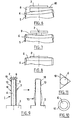
- FIG. 9 schematically represents a cold finger 1 of a device infrared observation camera with a hollow piece of elongated shape.
- the finger 1 is of cylindrical shape and of revolution.
- the cold finger 1 forms an interface between on the one hand a detector 2 infrared attached to one of its ends 6, and secondly a cryogenerator 3 arranged at the other end.
- the detector 2 is an infrared detector made of active material, for example of the piezoelectric or piezo-resistive material type.
- the cryogenerator 3 can be classically of the machine type known relaxation or known cyclic machine type.
- the cold finger 1 allows the cryogenerator 3 to cool and maintain the detector 2 at a working temperature.
- a fluid of 2 detector cooling circulates or is relaxed inside the finger 4 1.
- the cold finger 1 has thin walls 5 forming the sides 7 of the finger 1.
- the walls 5 of a finger 1 having a height of 50 mm and having an outer diameter of the order of 6 to 10 mm have a thickness of the order 0.1 mm.
- the finger 1 is made of metal, for example steel stainless or titanium alloy.
- the cold finger 1 has on its lateral surface at least one reinforcing fin 10.
- Each fin 10 extends substantially radially with respect to the side surface of the finger 1. A non-radial extension is of course possible. Each fin can thus move, during its extension from from the elongated piece of the cold finger to the detector 2 or to the cryogenerator 3. The base of each fin however forms a strapping at the level of the elongated piece of the finger.
- each fin compared to the finger length is limited.
- the ratio of the longitudinal extension of each fin at the cold finger compared to the height of the cold finger is for example between the values 1/20 and 1/200, preferentially between 1/30 and 1/100, and very preferably of the order of 1/50.
- the longitudinal extension of each fin at the junction between said fin and the elongate piece of the finger is just sufficient to give the rigidity to the fin, while being easy to machine. The fin thus forms a ring around the elongated piece of the cold finger.
- each fin 10 is to locally stiffen the wall 5 of the finger 1 in order to avoid its deformation, and in particular of its end. the end 6 is not deformed, it does not cause a deformation of the 2.
- the wall 5 is therefore thicker locally.
- the fins 10 increase the thickness of the walls 5 of the finger 1 locally - and not all the way up the finger as for the solution of Figure 8 - not to increase significantly the average section of the walls 5. Thus, it does not increase not significantly the thermal mass of the finger 1. The losses thermal in the walls 5 are therefore reduced to a minimum.
- Each fin 10 plays vis-à-vis the deformation of the finger 1 the same role of a rim of a barrel that prevents the moat from departing under the effect of the pressure of the liquid.
- the thermal mass of the finger 1 certainly increases, but very low, depending on the geometry, number and position of the fins on the finger.
- Each fin 10 can be made of material on the lateral surface.
- the manufacturing complexity of the finger increases.
- Each fin 10 can be attached to the outer lateral surface of the elongated piece forming the main part of the finger and slipped around the finger, like a ring.
- the fin 10 it is possible to choose for the fin 10 a material having a coefficient of thermal expansion different from the elongate part of the finger 1.
- each fin 10 can to be smaller than that of the elongated part of the finger 1.
- Each fin 10 squeezes more the elongated piece of the finger 1 as and when the temperature of the detector 2 and the finger during the operation of the device observation.
- the shapes of the longitudinal section and the radial section of each fin, as well as their dimensions are chosen to minimize finger distortion and thermal losses in the fins.
- the longitudinal sections of the fins can be rectangles as shown in Figure 9, or triangular for example or of any shape.
- each fin 10 relative to the finger 1 can be any.
- each fin 10 can be shaped circular ring as shown in fig 10, or triangle-shaped in which would be written the finger 1 as shown in Figure 11. Others longitudinal sections of the fins are of course possible.
- the surface of the fins 10 is limited. radiation losses are minimized - by still getting reinforcement function and minimizing deformation.
- the number and the distribution of the fins 10 with respect to others on the one hand and in relation to the finger on the other hand are also chosen to minimize finger distortion and thermal losses in the fins 10.
- the distribution of the fins 10 takes into account in particular the fact that the temperature gradient is lower in the lower part of the near finger of the cryogenerator than in the upper part or the detector is in continuously heated by the photon flux of the observation.
Landscapes
- Engineering & Computer Science (AREA)
- Physics & Mathematics (AREA)
- General Physics & Mathematics (AREA)
- Spectroscopy & Molecular Physics (AREA)
- Chemical & Material Sciences (AREA)
- Combustion & Propulsion (AREA)
- Mechanical Engineering (AREA)
- Thermal Sciences (AREA)
- General Engineering & Computer Science (AREA)
- Photometry And Measurement Of Optical Pulse Characteristics (AREA)
Applications Claiming Priority (2)
| Application Number | Priority Date | Filing Date | Title |
|---|---|---|---|
| FR0313585 | 2003-11-20 | ||
| FR0313585A FR2862839B1 (fr) | 2003-11-20 | 2003-11-20 | Doigt froid et dispositif d'observation comportant un tel doigt |
Publications (2)
| Publication Number | Publication Date |
|---|---|
| EP1533582A1 true EP1533582A1 (de) | 2005-05-25 |
| EP1533582B1 EP1533582B1 (de) | 2015-05-20 |
Family
ID=34430028
Family Applications (1)
| Application Number | Title | Priority Date | Filing Date |
|---|---|---|---|
| EP20040292739 Expired - Lifetime EP1533582B1 (de) | 2003-11-20 | 2004-11-19 | Kaltkopf und Observationsvorrichtung mit solchem Gerat |
Country Status (2)
| Country | Link |
|---|---|
| EP (1) | EP1533582B1 (de) |
| FR (1) | FR2862839B1 (de) |
Cited By (2)
| Publication number | Priority date | Publication date | Assignee | Title |
|---|---|---|---|---|
| US7415830B2 (en) | 2005-08-31 | 2008-08-26 | Raytheon Company | Method and system for cryogenic cooling |
| US11913703B2 (en) | 2020-04-03 | 2024-02-27 | Onto Innovation Inc. | Enhanced heat transfer in liquefied gas cooled detector |
Citations (5)
| Publication number | Priority date | Publication date | Assignee | Title |
|---|---|---|---|---|
| US4597175A (en) * | 1983-08-10 | 1986-07-01 | Ford Aerospace & Communications Corporation | Method for making infrared detector dewar |
| US4918312A (en) * | 1988-11-23 | 1990-04-17 | Santa Barbara Research Center | Dewar coldfinger |
| US5041727A (en) * | 1989-02-22 | 1991-08-20 | Hitachi, Ltd. | Spectrophotometer with near infrared radiation sensor having an improved sensitivity |
| EP0494001A1 (de) * | 1991-01-04 | 1992-07-08 | SAT (Société Anonyme de Télécommunications) | Kühlfinger für Halbleiterschaltung und kryogenische Anordnung mit solchem Finger |
| EP0823601A1 (de) * | 1996-08-07 | 1998-02-11 | Sagem Sa | Verbindungsvorrichtung bei Tiefsttemperaturen |
Family Cites Families (1)
| Publication number | Priority date | Publication date | Assignee | Title |
|---|---|---|---|---|
| US5382797A (en) * | 1990-12-21 | 1995-01-17 | Santa Barbara Research Center | Fast cooldown cryostat for large infrared focal plane arrays |
-
2003
- 2003-11-20 FR FR0313585A patent/FR2862839B1/fr not_active Expired - Fee Related
-
2004
- 2004-11-19 EP EP20040292739 patent/EP1533582B1/de not_active Expired - Lifetime
Patent Citations (5)
| Publication number | Priority date | Publication date | Assignee | Title |
|---|---|---|---|---|
| US4597175A (en) * | 1983-08-10 | 1986-07-01 | Ford Aerospace & Communications Corporation | Method for making infrared detector dewar |
| US4918312A (en) * | 1988-11-23 | 1990-04-17 | Santa Barbara Research Center | Dewar coldfinger |
| US5041727A (en) * | 1989-02-22 | 1991-08-20 | Hitachi, Ltd. | Spectrophotometer with near infrared radiation sensor having an improved sensitivity |
| EP0494001A1 (de) * | 1991-01-04 | 1992-07-08 | SAT (Société Anonyme de Télécommunications) | Kühlfinger für Halbleiterschaltung und kryogenische Anordnung mit solchem Finger |
| EP0823601A1 (de) * | 1996-08-07 | 1998-02-11 | Sagem Sa | Verbindungsvorrichtung bei Tiefsttemperaturen |
Cited By (3)
| Publication number | Priority date | Publication date | Assignee | Title |
|---|---|---|---|---|
| US7415830B2 (en) | 2005-08-31 | 2008-08-26 | Raytheon Company | Method and system for cryogenic cooling |
| WO2007027822A3 (en) * | 2005-08-31 | 2009-10-08 | Raytheon Company | Method and system for cryogenic cooling |
| US11913703B2 (en) | 2020-04-03 | 2024-02-27 | Onto Innovation Inc. | Enhanced heat transfer in liquefied gas cooled detector |
Also Published As
| Publication number | Publication date |
|---|---|
| FR2862839A1 (fr) | 2005-05-27 |
| FR2862839B1 (fr) | 2006-12-08 |
| EP1533582B1 (de) | 2015-05-20 |
Similar Documents
| Publication | Publication Date | Title |
|---|---|---|
| EP3894735B1 (de) | Stützvorrichtung und lagerbehälter für flüssiggas | |
| EP2824777B1 (de) | Laserkristall, der ein Kühlsystem für den Kristall mit einer Flüssigkeit umfasst | |
| EP2652844B1 (de) | Laserverstärkungsmodul und dessen herstellungsverfahren | |
| FR2956340A1 (fr) | Procede et dispositif de demontage d'une bague fermement ajustee dans un alesage | |
| FR2566197A1 (fr) | Laser a gaz carbonique plie | |
| EP1533582B1 (de) | Kaltkopf und Observationsvorrichtung mit solchem Gerat | |
| FR2806835A1 (fr) | Systeme de capteur/support destine notamment a la detection d'un rayonnement | |
| EP2796942A1 (de) | Befestigungsmethode eines Uhrwerks in einem Gehäuse | |
| FR2688321A1 (fr) | Miroir deformable. | |
| FR3072448B1 (fr) | Chambre de combustion de turbomachine | |
| FR2952429A1 (fr) | Capteur gyroscopique et procede de fabrication d'un tel capteur | |
| EP1999826B1 (de) | Laserverstärkungsvorrichtung mit tieftemperaturkühlung | |
| BE1012408A3 (fr) | Oscillateur de laser a gaz. | |
| EP0494001B1 (de) | Kühlfinger für Halbleiterschaltung und kryogenische Anordnung mit solchem Finger | |
| FR2723435A1 (fr) | Systeme de refroidisseur cryogenique a bout froid soude | |
| EP3695492B1 (de) | Elektrische maschine und verfahren zur herstellung davon | |
| EP0517638B1 (de) | Durch Wasserfilm gekühlte Modulardüse, insbesondere für Hochtemperaturtests von Proben oder ähnlichem | |
| EP3217137A1 (de) | Vorrichtung zur thermischen kühlung eines objekts mithilfe einer kühlquelle, wie etwa einem kühlmittelbad | |
| BE1023692B1 (fr) | Tube bimetallique pour recepteur solaire | |
| WO2023118180A1 (fr) | Unité de stockage de fluide cryogénique | |
| EP0237801A1 (de) | Laser mit mindestens einer Abdichtung | |
| EP0348299B1 (de) | Wärmeaustauscher | |
| FR3147478A1 (fr) | Inducteur pour four à induction | |
| FR3153130A1 (fr) | Unité de stockage de fluide cryogénique | |
| WO2000037198A1 (fr) | Face laterale pour installation de coulee continue de bandes metalliques |
Legal Events
| Date | Code | Title | Description |
|---|---|---|---|
| PUAI | Public reference made under article 153(3) epc to a published international application that has entered the european phase |
Free format text: ORIGINAL CODE: 0009012 |
|
| 17P | Request for examination filed |
Effective date: 20041126 |
|
| AK | Designated contracting states |
Kind code of ref document: A1 Designated state(s): AT BE BG CH CY CZ DE DK EE ES FI FR GB GR HU IE IS IT LI LU MC NL PL PT RO SE SI SK TR |
|
| AX | Request for extension of the european patent |
Extension state: AL HR LT LV MK YU |
|
| AKX | Designation fees paid |
Designated state(s): DE FR GB |
|
| RAP1 | Party data changed (applicant data changed or rights of an application transferred) |
Owner name: SAGEM DEFENSE SECURITE |
|
| 17Q | First examination report despatched |
Effective date: 20090610 |
|
| RAP1 | Party data changed (applicant data changed or rights of an application transferred) |
Owner name: SAGEM DEFENSE SECURITE |
|
| GRAP | Despatch of communication of intention to grant a patent |
Free format text: ORIGINAL CODE: EPIDOSNIGR1 |
|
| INTG | Intention to grant announced |
Effective date: 20150109 |
|
| GRAS | Grant fee paid |
Free format text: ORIGINAL CODE: EPIDOSNIGR3 |
|
| GRAA | (expected) grant |
Free format text: ORIGINAL CODE: 0009210 |
|
| AK | Designated contracting states |
Kind code of ref document: B1 Designated state(s): DE FR GB |
|
| REG | Reference to a national code |
Ref country code: GB Ref legal event code: FG4D Free format text: NOT ENGLISH |
|
| REG | Reference to a national code |
Ref country code: DE Ref legal event code: R096 Ref document number: 602004047209 Country of ref document: DE |
|
| REG | Reference to a national code |
Ref country code: FR Ref legal event code: PLFP Year of fee payment: 12 |
|
| REG | Reference to a national code |
Ref country code: DE Ref legal event code: R097 Ref document number: 602004047209 Country of ref document: DE |
|
| PLBE | No opposition filed within time limit |
Free format text: ORIGINAL CODE: 0009261 |
|
| STAA | Information on the status of an ep patent application or granted ep patent |
Free format text: STATUS: NO OPPOSITION FILED WITHIN TIME LIMIT |
|
| 26N | No opposition filed |
Effective date: 20160223 |
|
| REG | Reference to a national code |
Ref country code: FR Ref legal event code: PLFP Year of fee payment: 13 |
|
| REG | Reference to a national code |
Ref country code: FR Ref legal event code: PLFP Year of fee payment: 14 |
|
| REG | Reference to a national code |
Ref country code: FR Ref legal event code: PLFP Year of fee payment: 15 |
|
| PGFP | Annual fee paid to national office [announced via postgrant information from national office to epo] |
Ref country code: DE Payment date: 20191021 Year of fee payment: 16 |
|
| PGFP | Annual fee paid to national office [announced via postgrant information from national office to epo] |
Ref country code: GB Payment date: 20191022 Year of fee payment: 16 |
|
| REG | Reference to a national code |
Ref country code: DE Ref legal event code: R119 Ref document number: 602004047209 Country of ref document: DE |
|
| GBPC | Gb: european patent ceased through non-payment of renewal fee |
Effective date: 20201119 |
|
| PG25 | Lapsed in a contracting state [announced via postgrant information from national office to epo] |
Ref country code: DE Free format text: LAPSE BECAUSE OF NON-PAYMENT OF DUE FEES Effective date: 20210601 Ref country code: GB Free format text: LAPSE BECAUSE OF NON-PAYMENT OF DUE FEES Effective date: 20201119 |
|
| PGFP | Annual fee paid to national office [announced via postgrant information from national office to epo] |
Ref country code: FR Payment date: 20231020 Year of fee payment: 20 |