EP1533463A2 - Support plates - Google Patents
Support plates Download PDFInfo
- Publication number
- EP1533463A2 EP1533463A2 EP04380178A EP04380178A EP1533463A2 EP 1533463 A2 EP1533463 A2 EP 1533463A2 EP 04380178 A EP04380178 A EP 04380178A EP 04380178 A EP04380178 A EP 04380178A EP 1533463 A2 EP1533463 A2 EP 1533463A2
- Authority
- EP
- European Patent Office
- Prior art keywords
- flange
- head
- base
- recess
- rectangular
- Prior art date
- Legal status (The legal status is an assumption and is not a legal conclusion. Google has not performed a legal analysis and makes no representation as to the accuracy of the status listed.)
- Withdrawn
Links
- 238000006073 displacement reaction Methods 0.000 claims description 3
- 238000011084 recovery Methods 0.000 claims description 2
- 230000002787 reinforcement Effects 0.000 claims 1
- 235000012431 wafers Nutrition 0.000 description 4
- 239000002184 metal Substances 0.000 description 3
- 230000006978 adaptation Effects 0.000 description 2
- 240000008042 Zea mays Species 0.000 description 1
- 238000005452 bending Methods 0.000 description 1
- 210000000080 chela (arthropods) Anatomy 0.000 description 1
- 238000001125 extrusion Methods 0.000 description 1
- 238000002347 injection Methods 0.000 description 1
- 239000007924 injection Substances 0.000 description 1
- 239000000463 material Substances 0.000 description 1
- 238000000465 moulding Methods 0.000 description 1
- 230000002441 reversible effect Effects 0.000 description 1
- 238000000926 separation method Methods 0.000 description 1
Images


Classifications
-
- E—FIXED CONSTRUCTIONS
- E06—DOORS, WINDOWS, SHUTTERS, OR ROLLER BLINDS IN GENERAL; LADDERS
- E06B—FIXED OR MOVABLE CLOSURES FOR OPENINGS IN BUILDINGS, VEHICLES, FENCES OR LIKE ENCLOSURES IN GENERAL, e.g. DOORS, WINDOWS, BLINDS, GATES
- E06B9/00—Screening or protective devices for wall or similar openings, with or without operating or securing mechanisms; Closures of similar construction
- E06B9/24—Screens or other constructions affording protection against light, especially against sunshine; Similar screens for privacy or appearance; Slat blinds
- E06B9/26—Lamellar or like blinds, e.g. venetian blinds
- E06B9/36—Lamellar or like blinds, e.g. venetian blinds with vertical lamellae ; Supporting rails therefor
- E06B9/367—Lamellae suspensions ; Bottom weights; Bottom guides
Definitions
- the present invention relates to carrier plates used for suspend vertical curtain blades, especially blades made of rows of metal chains for use in curtains, these wafers being essentially characterized in that their use is universal, i.e. immediately applicable to the various types of travel amounts on existing slide in the trade, and in that they are provided with a notch of the characteristics of which will be detailed below.
- the platelets known up to now have the disadvantage of their resistance limited, so that in the case where they would be used for blades having a weight considerable, such as the blades of rows of metal chains, they deform because they are unable to bear all the weight.
- the support plates with a safety catch, object of this utility model appropriately solve the disadvantages mentioned because, in addition to a structure new enough reinforced to prevent deformation by being overweight, it offers a fixing area that is immediately adaptable, by its shape, to various types of commercially available amounts and, ultimately, it has a easy to place device, similar to a flange, guaranteeing with safety maximum that the mounting amount is removable and that it moves, whatever it is.
- Figure 13 is a view similar to the previous one, with the amount already placed in its place and indicating the location of the safety flange, properly secured.
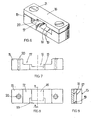
- the support plate object of this patent of invention and provided with a safety catch and intended to suspend the blades curtains consists of a laminar body, with a rectangular structure and symmetrical (1), preferably manufactured by extrusion or injection, to the part bottom of which it has a series of equal circular holes (2) preferably aligned and equidistant, so that the rows of metal chains (3) forming the curtain blade is suspended there.
- this flange (4) make the plates (1) remain separate as they accumulate due to displacement, avoiding that the rows of chains are mixed, this plate (1) having in addition the most small duly staggered (1a) and (1b) so that the correct recovery is easier when all the support plates (1) are deployed.
- the upper central part of the support plate (1) is extended in a head (5) precisely structured to allow immediate adaptation to different amounts existing in the trade.
- a head (5) precisely structured to allow immediate adaptation to different amounts existing in the trade.
- two small flanges (5a) and (5b) are there, protruding from the upper edge of the head (5) to make the positioning and fixing the amount easier, edges that are located symmetrically on this edge.
- This central opening (7) is an essential characteristic of the invention which is described and has a periphery having the following forms:
- This area (8) has two expansions in the opposite direction quadrangular (9,9 '), ending in an upper zone having a trapezoidal shape (10) while the upper edges of the quadrangular expansions (9) (9 ') are the beginning of inclined ramps (11) (11 ') upwards and outwards as a recess from this zone lateral lugs (6) (6 ') of the opening (7).
- This form of opening (7) allows any of the many amounts existing in the trade, can be placed, suspended and adjusted correctly by its hooks.
- a model of the "pincer" type (12) is shown which is extended by its upper part on a cylindrical pivot (13), common to the various types of amount, by having a clip (14) on its inner face.
- the safety element available to the support plate (1) which is the object of this invention consists of a flange composed of two fundamental pieces, i.e., by a base (15) and its cover (16), which are fixed together by means of screw (21), when the base and the cover face each other and are aligned so that that they coincide.
- Both the base (15) and the cover (16) of the flange are preferably obtained by molding.
- This base preferably has a prismatic shape rectangular, having a large recess, also prismatic (17) which, at its tower, has on its central part a second recess also prismatic rectangular (18), with its inclined front part (19) of about 41 °, an inclination slightly wider than the recess (18), and therefore its ends are sides of the upper recess (17).
- This base (15) is perfectly symmetrical.
- the cylindrical orifices (20) suitably screwed, will allow the introduction of these screws (2 1) closing the flange.
- the cover (16) with the same surface dimensions as the base (15) but smaller, offers a central rectangular prismatic recess (22) and two cylindrical end holes and bevels (23) whose situation coincides with that of the holes (20) for the placement of said closure screws (21).
- This lid (16) is also perfectly symmetrical.
- All the hollows of the base (15) and the lid (16) when united forming the flange, constitute a space to perfectly surround the head (5) of the support plate (1) with the clip (14) of the amount (12) placed therein (see the example shown in Figures 12 and 13), avoiding that it detaches unintentionally, which would cause the fall of the blades of rows of chains which are hanging from the curtain of this support plate (1).
Landscapes
- Engineering & Computer Science (AREA)
- Structural Engineering (AREA)
- Architecture (AREA)
- Civil Engineering (AREA)
- Curtains And Furnishings For Windows Or Doors (AREA)
Abstract
Description
La présente invention concerne des plaquettes de support utilisées pour suspendre des lames verticales de rideaux, notamment les lames constituées par des rangs de chaínes métalliques pour leur utilisation dans des rideaux, ces plaquettes étant essentiellement caractérisées en ce que leur utilisation est universelle, c'est-à-dire applicable de façon immédiate aux divers types de montants de déplacement sur la glissière existant dans le commerce, et en ce qu'elles sont pourvues d'un cran de sûreté dont les caractéristiques seront détaillées ci-après.The present invention relates to carrier plates used for suspend vertical curtain blades, especially blades made of rows of metal chains for use in curtains, these wafers being essentially characterized in that their use is universal, i.e. immediately applicable to the various types of travel amounts on existing slide in the trade, and in that they are provided with a notch of the characteristics of which will be detailed below.
Sont habituellement très connus les rideaux formés par des lames verticales et pourvues de dispositifs permettant leur déplacement sur une glissière appropriée, installée à cet effet, ainsi qu'ils tournent dans le sens de leur axe vertical, ce qui permet de positionner la lame de sorte qu'elle permette une visibilité plus ou moins grande et, par conséquent, un passage de la lumière plus ou moins grand. Le déplacement sur cette glissière permet, comme on sait, de couvrir le tout ou partie de l'espace où le rideau a été installé, jusqu'à parvenir à son pliage total et à ce qu'elle n'occupe qu'un espace minimum sur une des extrémités de cet espace qu'il recouvre.Are usually well known curtains formed by vertical blades and provided with devices enabling them to be moved on a suitable slide, installed for this purpose, so that they rotate in the direction of their vertical axis, which allows to position the blade so that it allows more or less visibility large and, therefore, a passage of light more or less big. The moving on this slide allows, as we know, to cover all or part of the space where the curtain has been installed, until it is completely folded and occupies only a minimum space on one end of this space that it covers.
Les plaquettes connues jusqu'à présent ont l'inconvénient de leur résistance limitée, de sorte que dans le cas où on les utiliserait pour des lames ayant un poids considérable, telles que les lames de rangs de chaínes métalliques, elles se déforment car elles sont incapables de supporter tout le poids.The platelets known up to now have the disadvantage of their resistance limited, so that in the case where they would be used for blades having a weight considerable, such as the blades of rows of metal chains, they deform because they are unable to bear all the weight.
Une autre des inconvénients existant actuellement est l'impossibilité de les utiliser de façon universelle étant donnée la diversité des montants pour fixer les plaquettes et leur adaptation sur la glissière de déplacement.Another disadvantage that currently exists is the impossibility of use universally given the diversity of amounts to set the platelets and their adaptation on the slide of displacement.
Finalement, il faut remarquer également, comme un inconvénient, la facilité qu'ont les plaquettes existantes actuellement, à ce que les montants de fixation se détachent à cause du poids élevé, en entraínant la chute accidentelle de la lame de rideau, avec le danger que cela représente.Finally, we must also note, as a disadvantage, the ease existing platelets, that the amounts of fixation are loose because of the high weight, resulting in the accidental fall of the blade of curtain, with the danger that this represents.
Les plaquettes de support avec un cran de sûreté, objet de ce modèle d'utilité, résous convenablement les inconvénients évoqués car, en plus d'une structure nouvelle suffisamment renforcée pour éviter le déformation par l'excès de poids, celle-ci offre une zone de fixation immédiatement adaptable, de par sa forme, aux divers types de montants existant dans le commerce et, finalement, il possède un dispositif facile de placer , semblable à une bride, garantissant avec la sûreté maximale que le montant de fixation soit amovible et qu'il se déplace, quel qu'il soit.The support plates with a safety catch, object of this utility model, appropriately solve the disadvantages mentioned because, in addition to a structure new enough reinforced to prevent deformation by being overweight, it offers a fixing area that is immediately adaptable, by its shape, to various types of commercially available amounts and, ultimately, it has a easy to place device, similar to a flange, guaranteeing with safety maximum that the mounting amount is removable and that it moves, whatever it is.
Afin de décrire avec tous les détails les caractéristiques de la plaquette de support objet de cette invention, des dessins sont annexés dans lesquels sont représentés à titre d'exemple pratique no limitatif, une de ces plaquettes.In order to describe with all the details the characteristics of the plate of object of this invention, drawings are appended in which are represented as a non-limiting practical example, one of these platelets.
Dans ces dessins,
Finalement, la figure 13, est une vue semblable à la précédente, avec le montant déjà placé à sa place et indiquant l'emplacement de la bride de sûreté, convenablement fixée.Finally, Figure 13, is a view similar to the previous one, with the amount already placed in its place and indicating the location of the safety flange, properly secured.
Conformément à ces dessins, la plaquette de support objet de ce brevet d'invention et pourvue d'un cran de sûreté et destinée à suspendre les lames verticales de rideaux, consiste en un corps laminaire , à structure rectangulaire et symétrique (1), de préférence fabriqué par extrusion ou injection, à la partie inférieure duquel elle possède une série de trous circulaires égaux (2) de préférence alignés et équidistants, destinés à ce que les rangs de chaínes métalliques (3) formant la lame du rideau y soient suspendus.According to these drawings, the support plate object of this patent of invention and provided with a safety catch and intended to suspend the blades curtains, consists of a laminar body, with a rectangular structure and symmetrical (1), preferably manufactured by extrusion or injection, to the part bottom of which it has a series of equal circular holes (2) preferably aligned and equidistant, so that the rows of metal chains (3) forming the curtain blade is suspended there.
De la partie centrale d'une de ses faces, en position longitudinale et perpendiculaire, un volet ou rebord (4) à profil trapézoïdal, pas très haut, émerge, qui fournit de par sa position et ses caractéristiques une plus grande résistance à la flexion de la plaquette (1), en évitant la possible déformation de cette plaquette (1) lorsqu'elle supporte un poids considérable de rangs de chaínes (3).From the central part of one of its faces, in longitudinal position and perpendicular, a flap or flange (4) trapezoidal profile, not very high, emerges, which provides by its position and its characteristics a greater resistance to the bending of the wafer (1), avoiding the possible deformation of this wafer (1) when it supports a considerable weight of rows of chains (3).
Par ailleurs, la taille et l'agencement de ce rebord (4) font que les plaquettes (1) restent séparées lorsqu'elles s'accumulent à cause du déplacement, en évitant que les rangs de chaínes se mélangent, cette plaquette (1) ayant de plus les côtés les plus petits dûment échelonnés (1a) et (1b) pour que le recouvrement correct soit plus aisé lorsque toutes les plaquettes de support (1) sont déployées.Moreover, the size and the arrangement of this flange (4) make the plates (1) remain separate as they accumulate due to displacement, avoiding that the rows of chains are mixed, this plate (1) having in addition the most small duly staggered (1a) and (1b) so that the correct recovery is easier when all the support plates (1) are deployed.
La partie supérieure centrale de la plaquette de support (1) est prolongée en une tête (5) structurée de façon précise pour permettre l'adaptation immédiate aux différents montants existant dans le commerce. Pour cela, deux petits rebords (5a) et (5b) se trouvent là, dépassant le bord supérieur de la tête (5) pour rendre le positionnement et la fixation du montant plus aisés, des rebords qui sont situées symétriquement sur ce bord.The upper central part of the support plate (1) is extended in a head (5) precisely structured to allow immediate adaptation to different amounts existing in the trade. For this, two small flanges (5a) and (5b) are there, protruding from the upper edge of the head (5) to make the positioning and fixing the amount easier, edges that are located symmetrically on this edge.
Sur la face arrière de la propre tête (5) et recouvrant la face arrière de la plaquette, il se trouve deux pattes parallèles et identiques (6) (6') délimitant une ouverture centrale (7) de cette tête (5). On the back side of the own head (5) and covering the back side of the plate, there are two parallel and identical legs (6) (6 ') delimiting a central opening (7) of this head (5).
Cette ouverture centrale (7) constitue une caractéristique essentielle de l'invention qui est décrite et possède un pourtour ayant les formes suivantes:This central opening (7) is an essential characteristic of the invention which is described and has a periphery having the following forms:
Tout d'abord, une zone inférieure rectangulaire (8), délimitée sur la face arrière de la plaquette par les bords internes des deux pattes (6) (6'). Cette zone (8) possède, sur ses sommets supérieurs, deux expansions en sens inverse quadrangulaires (9,9'), finissant en une zone supérieure ayant une forme trapézoïdale (10) tandis que les arêtes supérieures des expansions quadrangulaires (9)(9') sont le début de rampes inclinées (11)(11') vers le haut et vers l'extérieur, comme évidement de cette zone des pattes latérales (6)(6') de l'ouverture (7). Cette forme de l'ouverture (7) permet qu'un quelconque des nombreux montants existant dans le commerce, puisse être placé, suspendu et réglé correctement par ses crochets.First, a rectangular lower zone (8) delimited on the face rear of the wafer by the inner edges of the two legs (6) (6 '). This area (8) has two expansions in the opposite direction quadrangular (9,9 '), ending in an upper zone having a trapezoidal shape (10) while the upper edges of the quadrangular expansions (9) (9 ') are the beginning of inclined ramps (11) (11 ') upwards and outwards as a recess from this zone lateral lugs (6) (6 ') of the opening (7). This form of opening (7) allows any of the many amounts existing in the trade, can be placed, suspended and adjusted correctly by its hooks.
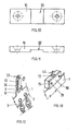
Un type de modèle de ces montants est illustré dans la figure 12, à titre d'échantillon ou d'exemple de ceux existant dans le commerce. Ils possèdent toujours tous un élément qui sera fixé à une tête (5) de la plaquette de support (1), en finissant sur le train supérieur de fixation et de glissement sur la glissière du rideau (non représenté).A model type of these amounts is shown in Figure 12, as a sample or example of those commercially available. They own always an element which will be fixed to a head (5) of the support plate (1), in ending on the upper fastening and sliding gear on the curtain slide (not shown)
Dans l'exemple du montant de la figure 12, un modèle du genre "pince" (12) est représenté qui se prolonge par sa partie supérieure sur un pivot cylindrique (13), commun aux divers types de montant, en disposant d'un clip (14) sur sa face interne.In the example of the amount of FIG. 12, a model of the "pincer" type (12) is shown which is extended by its upper part on a cylindrical pivot (13), common to the various types of amount, by having a clip (14) on its inner face.
L'élément de sûreté dont dispose la plaquette de support (1) objet de cette invention consiste en une bride composée par deux pièces fondamentales, c'est-à-dire, par une base (15) et son couvercle (16), qui sont fixés entre eux au moyen de vis (21), lorsque la base et le couvercle se font face et sont alignés de façon à ce qu'ils coïncident.The safety element available to the support plate (1) which is the object of this invention consists of a flange composed of two fundamental pieces, i.e., by a base (15) and its cover (16), which are fixed together by means of screw (21), when the base and the cover face each other and are aligned so that that they coincide.
Aussi bien la base (15) que le couvercle (16) de la bride seront de préférence obtenus par moulage. Cette base a de préférence une forme prismatique rectangulaire, possédant un vaste évidement, également prismatique (17) qui, à son tour, dispose sur sa partie centrale d'une deuxième évidement également prismatique rectangulaire (18), avec sa partie avant inclinée (19) d'environ 41 °, une inclinaison légèrement plus large que l'évidement (18), et donc ses extrémités portent sur les côtés de l'évidement supérieur (17). Cette base (15) est parfaitement symétrique.Both the base (15) and the cover (16) of the flange are preferably obtained by molding. This base preferably has a prismatic shape rectangular, having a large recess, also prismatic (17) which, at its tower, has on its central part a second recess also prismatic rectangular (18), with its inclined front part (19) of about 41 °, an inclination slightly wider than the recess (18), and therefore its ends are sides of the upper recess (17). This base (15) is perfectly symmetrical.
Les orifices cylindriques (20) convenablement vissés, permettront l'introduction de ces vis (2 1 ) de fermeture de la bride.The cylindrical orifices (20) suitably screwed, will allow the introduction of these screws (2 1) closing the flange.
Le couvercle (16) aux dimensions de surface identiques à la base (15) mais de moindre grosseur, offre un évidement prismatique rectangulaire central (22) et deux trous cylindriques d'extrémité et biseautés (23) dont la situation coïncide avec celle des trous (20) pour le placement desdits vis de fermeture (21). Ce couvercle (16) est également parfaitement symétrique.The cover (16) with the same surface dimensions as the base (15) but smaller, offers a central rectangular prismatic recess (22) and two cylindrical end holes and bevels (23) whose situation coincides with that of the holes (20) for the placement of said closure screws (21). This lid (16) is also perfectly symmetrical.
L'ensemble des creux de la base (15) et du couvercle (16) lorsqu'ils sont unis formant la bride, constituent un espace permettant d'entourer parfaitement la tête (5) de la plaquette de support (1) avec le clip (14) du montant (12) qui y est placé, (voir l'exemple illustré dans les figures 12 et 13), en évitant qu'il ne se détache involontairement, ce qui entraínerait la chute des lames de rangs de chaínes qui sont suspendues au rideau de cette plaquette de support (1).All the hollows of the base (15) and the lid (16) when united forming the flange, constitute a space to perfectly surround the head (5) of the support plate (1) with the clip (14) of the amount (12) placed therein (see the example shown in Figures 12 and 13), avoiding that it detaches unintentionally, which would cause the fall of the blades of rows of chains which are hanging from the curtain of this support plate (1).
Ainsi donc, au moment où le clip (14) du montant (12) est convenablement fixé à l'ouverture (7) de la tête (7) on dispose sur les deux côtés, avant et arrière, le couvercle (16) et la base (15), en plaçant la zone du montant (12) qui doit rester unie à la tête (5) à l'intérieur du creux formé par les évidements (17), (18) et (22) en fixant ensuite fortement la bride au moyen de vis de serrage et de fixation (21). Une action en sens inverse, en séparant la base (15) et le couvercle (16) permettra la séparation du montant (12) lorsqu'on souhaitera manipuler une lame de rangs de chaínes de rideau suspendue de la plaquette de support (1).Thus, at the moment when the clip (14) of the amount (12) is suitably attached to the opening (7) of the head (7) there is on both sides, front and rear, the cover (16) and the base (15), placing the area of the upright (12) which must remain united at the head (5) inside the hollow formed by the recesses (17), (18) and (22) in then strongly fixing the flange by means of clamping screws and fixing (21). A reverse action, separating the base (15) and the cover (16) will allow the separation of the amount (12) when one wishes to manipulate a blade of rows of curtain chains suspended from the support plate (1).
Tel que décrit et étant données les caractéristiques spéciales des entrants que la base (15) et le couvercle (16) de la bride possèdent, celle-ci pourra être utilisée immédiatement sur tous genres de montant des nombreux existant dans le commerce.As described and given the special characteristics of the entrants that the base (15) and the cover (16) of the flange have, it can be used immediately on all kinds of amount of the many existing in the trade.
L'objet de cette invention ayant été suffisamment décrit, il faut signaler que toute variation des dimensions, formes, finition et aspect extérieur, ainsi que le genre de matériaux utilisés pour la mise en oeuvre de l'objet de l'invention, n'altèreront en rien l'esprit de ce modèle d'utilité résumés dans les revendications annexées.The subject of this invention having been sufficiently described, it should be pointed out that any variation in size, shape, finish and appearance, as well as the type materials used for the implementation of the object of the invention, will not alter nothing the spirit of this utility model summarized in the appended claims.
Claims (4)
que les différents rangs de chaínes (3) se mélangent et en permettant de plus un recouvrement lorsqu'elles sont toutes étendues, grâce à leurs extrémités échelonnées (1a, 1b), dont elles sont pourvues , et il est prévu que ce corps laminaire soit étendu en une tête (5) pourvue d'une ouverture centrale (7) à pourtour adapté pour permettre de placer à travers des crochets ou des éléments semblables les montants qui, connus et existant dans le commerce, vont soutenir la plaquette de support correspondante.Supporting plates with a safety catch for suspending curtains of vertical chain length blades, essentially characterized in that they comprise a rectangular and symmetrical laminar body (1) associated with a fastening flange (15-16), laminar body (1) being provided at its lower part with a series of circular holes (2) to suspend the rows of chains (3), in longitudinal position and perpendicular to one of its faces, a flap or reinforcement rim to trapezoidal profile and not very high (3) emerges, a shutter which at the same time separates the platelets when they accumulate by the displacement while avoiding
that the different rows of chains (3) are mixed and allowing more recovery when they are all extended, thanks to their staggered ends (1a, 1b), which they are provided, and it is expected that this laminar body is extended to a head (5) provided with a central opening (7) circumferentially adapted to allow to place through brackets or similar elements the amounts which, known and existing commercially, will support the corresponding support plate.
Applications Claiming Priority (2)
| Application Number | Priority Date | Filing Date | Title |
|---|---|---|---|
| ES200302665U ES1056204Y (en) | 2003-11-19 | 2003-11-19 | PLATES-SUPPORT WITH RETAINING INSURANCE, FOR THE HANGING OF CURTAINS OF LAMPS OF VERTICAL CHAIN RISTERS. |
| ES200302665U | 2003-11-19 |
Publications (1)
| Publication Number | Publication Date |
|---|---|
| EP1533463A2 true EP1533463A2 (en) | 2005-05-25 |
Family
ID=31970695
Family Applications (1)
| Application Number | Title | Priority Date | Filing Date |
|---|---|---|---|
| EP04380178A Withdrawn EP1533463A2 (en) | 2003-11-19 | 2004-09-07 | Support plates |
Country Status (2)
| Country | Link |
|---|---|
| EP (1) | EP1533463A2 (en) |
| ES (1) | ES1056204Y (en) |
-
2003
- 2003-11-19 ES ES200302665U patent/ES1056204Y/en not_active Expired - Fee Related
-
2004
- 2004-09-07 EP EP04380178A patent/EP1533463A2/en not_active Withdrawn
Also Published As
| Publication number | Publication date |
|---|---|
| ES1056204U (en) | 2004-03-01 |
| ES1056204Y (en) | 2004-06-16 |
Similar Documents
| Publication | Publication Date | Title |
|---|---|---|
| EP0802145A1 (en) | Hoisting yoke | |
| LU85061A1 (en) | DEVICE AND METHOD FOR CONNECTING RETAINING AND CONSOLIDATION RATES | |
| EP0751599A1 (en) | Means for attaching horizontal brackets to a vertical stand with rack and pinion means | |
| WO2013060962A1 (en) | Support device for positioning cables along submerged pipeline-type pipes | |
| EP2915936A2 (en) | Connection between a fence and a post | |
| EP3521536A1 (en) | Part for attaching at least one mesh panel to a fence post, corresponding fence post and installation tool | |
| FR2914658A1 (en) | FLOATING PROTECTION SYSTEM AGAINST MOSSES OR POLLUTION | |
| FR2950916A1 (en) | Clip for fixing latticed panel of fence on post, has inverse U-shaped profile whose top part is provided with notch to allow passage of wire, where grip is provided at intersection of end wire and wire at post to avoid sliding of clip | |
| FR2966846A1 (en) | MODULAR WALL RING DEVICE AND EXTENSION SYSTEM USING THE SAME DEVICE. | |
| FR2852640A1 (en) | Coating fixation device for flat deck truck, has foldable linking ring associating base component with tightening unit by re-pushing direction control rod between coating wall and rail | |
| EP1533463A2 (en) | Support plates | |
| FR2966495A1 (en) | REMOVABLE SCALE SYSTEM FOR HOUSING OR STORAGE MODULE, SCALE ADAPTED TO THE SYSTEM | |
| FR2564303A1 (en) | ADJUSTABLE SHELVING | |
| EP0575269A1 (en) | Suspension device for cable channels | |
| FR2468540A1 (en) | DEVICE FOR HANGING AT LEAST ONE FORMWORK PANEL FROM THE HOOK OF A CRANE | |
| EP1467933B1 (en) | Device for dividing a receptacle into compartments for sorting objects | |
| FR2495884A1 (en) | Frame for rigidly holding printed circuit cards in prodn. treatments - has parallel cross-members, within rigid frame, each having mutually facing rims on which boards are supported in soldering tanks | |
| FR2468518A1 (en) | DEVICE FOR HOLDING STACKS OF FORMWORK PANELS | |
| EP2792818B1 (en) | Fence post for simplified assembly of a fence panel | |
| FR2905823A1 (en) | Oyster farming bag hooking device for e.g. metallic side-rail in beach, has intermediate segment extended between side-rail and lower segment that forms transport element of handle received and maintained in space delimited by segments | |
| FR2496741A3 (en) | Connector for tubular scaffolding - uses annular link collars surrounding vertical tubes to receive ends of horizontal tubes | |
| FR2623241A1 (en) | Device for fixing a ladder on a corner of a column (post) | |
| FR2536128A1 (en) | Elastic clip for fixing a panel to a support | |
| EP1408194B1 (en) | Bearing for vertical lamella, comprising a security device | |
| FR2917320A1 (en) | MODULAR GAFFE FOR COVERING ELEMENT. |
Legal Events
| Date | Code | Title | Description |
|---|---|---|---|
| PUAI | Public reference made under article 153(3) epc to a published international application that has entered the european phase |
Free format text: ORIGINAL CODE: 0009012 |
|
| AK | Designated contracting states |
Kind code of ref document: A2 Designated state(s): AT BE BG CH CY CZ DE DK EE ES FI FR GB GR HU IE IT LI LU MC NL PL PT RO SE SI SK TR |
|
| AX | Request for extension of the european patent |
Extension state: AL HR LT LV MK |
|
| 17P | Request for examination filed |
Effective date: 20050425 |
|
| STAA | Information on the status of an ep patent application or granted ep patent |
Free format text: STATUS: THE APPLICATION IS DEEMED TO BE WITHDRAWN |
|
| 18D | Application deemed to be withdrawn |
Effective date: 20070331 |