EP1533433A1 - Panneau sandwich et procédé de sa fabrication - Google Patents
Panneau sandwich et procédé de sa fabrication Download PDFInfo
- Publication number
- EP1533433A1 EP1533433A1 EP03027020A EP03027020A EP1533433A1 EP 1533433 A1 EP1533433 A1 EP 1533433A1 EP 03027020 A EP03027020 A EP 03027020A EP 03027020 A EP03027020 A EP 03027020A EP 1533433 A1 EP1533433 A1 EP 1533433A1
- Authority
- EP
- European Patent Office
- Prior art keywords
- core
- sandwich panel
- materials
- joints
- face plate
- Prior art date
- Legal status (The legal status is an assumption and is not a legal conclusion. Google has not performed a legal analysis and makes no representation as to the accuracy of the status listed.)
- Withdrawn
Links
Images


Classifications
-
- B—PERFORMING OPERATIONS; TRANSPORTING
- B32—LAYERED PRODUCTS
- B32B—LAYERED PRODUCTS, i.e. PRODUCTS BUILT-UP OF STRATA OF FLAT OR NON-FLAT, e.g. CELLULAR OR HONEYCOMB, FORM
- B32B3/00—Layered products comprising a layer with external or internal discontinuities or unevennesses, or a layer of non-planar form; Layered products having particular features of form
- B32B3/10—Layered products comprising a layer with external or internal discontinuities or unevennesses, or a layer of non-planar form; Layered products having particular features of form characterised by a discontinuous layer, i.e. formed of separate pieces of material
- B32B3/12—Layered products comprising a layer with external or internal discontinuities or unevennesses, or a layer of non-planar form; Layered products having particular features of form characterised by a discontinuous layer, i.e. formed of separate pieces of material characterised by a layer of regularly- arranged cells, e.g. a honeycomb structure
-
- B—PERFORMING OPERATIONS; TRANSPORTING
- B32—LAYERED PRODUCTS
- B32B—LAYERED PRODUCTS, i.e. PRODUCTS BUILT-UP OF STRATA OF FLAT OR NON-FLAT, e.g. CELLULAR OR HONEYCOMB, FORM
- B32B15/00—Layered products comprising a layer of metal
- B32B15/04—Layered products comprising a layer of metal comprising metal as the main or only constituent of a layer, which is next to another layer of the same or of a different material
- B32B15/043—Layered products comprising a layer of metal comprising metal as the main or only constituent of a layer, which is next to another layer of the same or of a different material of metal
-
- B—PERFORMING OPERATIONS; TRANSPORTING
- B32—LAYERED PRODUCTS
- B32B—LAYERED PRODUCTS, i.e. PRODUCTS BUILT-UP OF STRATA OF FLAT OR NON-FLAT, e.g. CELLULAR OR HONEYCOMB, FORM
- B32B15/00—Layered products comprising a layer of metal
- B32B15/04—Layered products comprising a layer of metal comprising metal as the main or only constituent of a layer, which is next to another layer of the same or of a different material
- B32B15/046—Layered products comprising a layer of metal comprising metal as the main or only constituent of a layer, which is next to another layer of the same or of a different material of foam
-
- B—PERFORMING OPERATIONS; TRANSPORTING
- B32—LAYERED PRODUCTS
- B32B—LAYERED PRODUCTS, i.e. PRODUCTS BUILT-UP OF STRATA OF FLAT OR NON-FLAT, e.g. CELLULAR OR HONEYCOMB, FORM
- B32B15/00—Layered products comprising a layer of metal
- B32B15/04—Layered products comprising a layer of metal comprising metal as the main or only constituent of a layer, which is next to another layer of the same or of a different material
- B32B15/08—Layered products comprising a layer of metal comprising metal as the main or only constituent of a layer, which is next to another layer of the same or of a different material of synthetic resin
-
- B—PERFORMING OPERATIONS; TRANSPORTING
- B32—LAYERED PRODUCTS
- B32B—LAYERED PRODUCTS, i.e. PRODUCTS BUILT-UP OF STRATA OF FLAT OR NON-FLAT, e.g. CELLULAR OR HONEYCOMB, FORM
- B32B15/00—Layered products comprising a layer of metal
- B32B15/04—Layered products comprising a layer of metal comprising metal as the main or only constituent of a layer, which is next to another layer of the same or of a different material
- B32B15/10—Layered products comprising a layer of metal comprising metal as the main or only constituent of a layer, which is next to another layer of the same or of a different material of wood
-
- B—PERFORMING OPERATIONS; TRANSPORTING
- B32—LAYERED PRODUCTS
- B32B—LAYERED PRODUCTS, i.e. PRODUCTS BUILT-UP OF STRATA OF FLAT OR NON-FLAT, e.g. CELLULAR OR HONEYCOMB, FORM
- B32B15/00—Layered products comprising a layer of metal
- B32B15/14—Layered products comprising a layer of metal next to a fibrous or filamentary layer
-
- B—PERFORMING OPERATIONS; TRANSPORTING
- B32—LAYERED PRODUCTS
- B32B—LAYERED PRODUCTS, i.e. PRODUCTS BUILT-UP OF STRATA OF FLAT OR NON-FLAT, e.g. CELLULAR OR HONEYCOMB, FORM
- B32B17/00—Layered products essentially comprising sheet glass, or glass, slag, or like fibres
- B32B17/02—Layered products essentially comprising sheet glass, or glass, slag, or like fibres in the form of fibres or filaments
- B32B17/04—Layered products essentially comprising sheet glass, or glass, slag, or like fibres in the form of fibres or filaments bonded with or embedded in a plastic substance
-
- B—PERFORMING OPERATIONS; TRANSPORTING
- B32—LAYERED PRODUCTS
- B32B—LAYERED PRODUCTS, i.e. PRODUCTS BUILT-UP OF STRATA OF FLAT OR NON-FLAT, e.g. CELLULAR OR HONEYCOMB, FORM
- B32B21/00—Layered products comprising a layer of wood, e.g. wood board, veneer, wood particle board
- B32B21/04—Layered products comprising a layer of wood, e.g. wood board, veneer, wood particle board comprising wood as the main or only constituent of a layer, which is next to another layer of the same or of a different material
- B32B21/042—Layered products comprising a layer of wood, e.g. wood board, veneer, wood particle board comprising wood as the main or only constituent of a layer, which is next to another layer of the same or of a different material of wood
-
- B—PERFORMING OPERATIONS; TRANSPORTING
- B32—LAYERED PRODUCTS
- B32B—LAYERED PRODUCTS, i.e. PRODUCTS BUILT-UP OF STRATA OF FLAT OR NON-FLAT, e.g. CELLULAR OR HONEYCOMB, FORM
- B32B21/00—Layered products comprising a layer of wood, e.g. wood board, veneer, wood particle board
- B32B21/04—Layered products comprising a layer of wood, e.g. wood board, veneer, wood particle board comprising wood as the main or only constituent of a layer, which is next to another layer of the same or of a different material
- B32B21/047—Layered products comprising a layer of wood, e.g. wood board, veneer, wood particle board comprising wood as the main or only constituent of a layer, which is next to another layer of the same or of a different material of foam
-
- B—PERFORMING OPERATIONS; TRANSPORTING
- B32—LAYERED PRODUCTS
- B32B—LAYERED PRODUCTS, i.e. PRODUCTS BUILT-UP OF STRATA OF FLAT OR NON-FLAT, e.g. CELLULAR OR HONEYCOMB, FORM
- B32B21/00—Layered products comprising a layer of wood, e.g. wood board, veneer, wood particle board
- B32B21/04—Layered products comprising a layer of wood, e.g. wood board, veneer, wood particle board comprising wood as the main or only constituent of a layer, which is next to another layer of the same or of a different material
- B32B21/08—Layered products comprising a layer of wood, e.g. wood board, veneer, wood particle board comprising wood as the main or only constituent of a layer, which is next to another layer of the same or of a different material of synthetic resin
-
- B—PERFORMING OPERATIONS; TRANSPORTING
- B32—LAYERED PRODUCTS
- B32B—LAYERED PRODUCTS, i.e. PRODUCTS BUILT-UP OF STRATA OF FLAT OR NON-FLAT, e.g. CELLULAR OR HONEYCOMB, FORM
- B32B21/00—Layered products comprising a layer of wood, e.g. wood board, veneer, wood particle board
- B32B21/10—Next to a fibrous or filamentary layer
-
- B—PERFORMING OPERATIONS; TRANSPORTING
- B32—LAYERED PRODUCTS
- B32B—LAYERED PRODUCTS, i.e. PRODUCTS BUILT-UP OF STRATA OF FLAT OR NON-FLAT, e.g. CELLULAR OR HONEYCOMB, FORM
- B32B27/00—Layered products comprising a layer of synthetic resin
- B32B27/06—Layered products comprising a layer of synthetic resin as the main or only constituent of a layer, which is next to another layer of the same or of a different material
- B32B27/065—Layered products comprising a layer of synthetic resin as the main or only constituent of a layer, which is next to another layer of the same or of a different material of foam
-
- B—PERFORMING OPERATIONS; TRANSPORTING
- B32—LAYERED PRODUCTS
- B32B—LAYERED PRODUCTS, i.e. PRODUCTS BUILT-UP OF STRATA OF FLAT OR NON-FLAT, e.g. CELLULAR OR HONEYCOMB, FORM
- B32B27/00—Layered products comprising a layer of synthetic resin
- B32B27/12—Layered products comprising a layer of synthetic resin next to a fibrous or filamentary layer
-
- B—PERFORMING OPERATIONS; TRANSPORTING
- B32—LAYERED PRODUCTS
- B32B—LAYERED PRODUCTS, i.e. PRODUCTS BUILT-UP OF STRATA OF FLAT OR NON-FLAT, e.g. CELLULAR OR HONEYCOMB, FORM
- B32B5/00—Layered products characterised by the non- homogeneity or physical structure, i.e. comprising a fibrous, filamentary, particulate or foam layer; Layered products characterised by having a layer differing constitutionally or physically in different parts
- B32B5/02—Layered products characterised by the non- homogeneity or physical structure, i.e. comprising a fibrous, filamentary, particulate or foam layer; Layered products characterised by having a layer differing constitutionally or physically in different parts characterised by structural features of a fibrous or filamentary layer
- B32B5/022—Non-woven fabric
-
- B—PERFORMING OPERATIONS; TRANSPORTING
- B32—LAYERED PRODUCTS
- B32B—LAYERED PRODUCTS, i.e. PRODUCTS BUILT-UP OF STRATA OF FLAT OR NON-FLAT, e.g. CELLULAR OR HONEYCOMB, FORM
- B32B5/00—Layered products characterised by the non- homogeneity or physical structure, i.e. comprising a fibrous, filamentary, particulate or foam layer; Layered products characterised by having a layer differing constitutionally or physically in different parts
- B32B5/18—Layered products characterised by the non- homogeneity or physical structure, i.e. comprising a fibrous, filamentary, particulate or foam layer; Layered products characterised by having a layer differing constitutionally or physically in different parts characterised by features of a layer of foamed material
-
- E—FIXED CONSTRUCTIONS
- E04—BUILDING
- E04C—STRUCTURAL ELEMENTS; BUILDING MATERIALS
- E04C2/00—Building elements of relatively thin form for the construction of parts of buildings, e.g. sheet materials, slabs, or panels
- E04C2/02—Building elements of relatively thin form for the construction of parts of buildings, e.g. sheet materials, slabs, or panels characterised by specified materials
- E04C2/26—Building elements of relatively thin form for the construction of parts of buildings, e.g. sheet materials, slabs, or panels characterised by specified materials composed of materials covered by two or more of groups E04C2/04, E04C2/08, E04C2/10 or of materials covered by one of these groups with a material not specified in one of the groups
- E04C2/284—Building elements of relatively thin form for the construction of parts of buildings, e.g. sheet materials, slabs, or panels characterised by specified materials composed of materials covered by two or more of groups E04C2/04, E04C2/08, E04C2/10 or of materials covered by one of these groups with a material not specified in one of the groups at least one of the materials being insulating
- E04C2/292—Building elements of relatively thin form for the construction of parts of buildings, e.g. sheet materials, slabs, or panels characterised by specified materials composed of materials covered by two or more of groups E04C2/04, E04C2/08, E04C2/10 or of materials covered by one of these groups with a material not specified in one of the groups at least one of the materials being insulating composed of insulating material and sheet metal
-
- E—FIXED CONSTRUCTIONS
- E04—BUILDING
- E04C—STRUCTURAL ELEMENTS; BUILDING MATERIALS
- E04C2/00—Building elements of relatively thin form for the construction of parts of buildings, e.g. sheet materials, slabs, or panels
- E04C2/30—Building elements of relatively thin form for the construction of parts of buildings, e.g. sheet materials, slabs, or panels characterised by the shape or structure
- E04C2/34—Building elements of relatively thin form for the construction of parts of buildings, e.g. sheet materials, slabs, or panels characterised by the shape or structure composed of two or more spaced sheet-like parts
-
- Y—GENERAL TAGGING OF NEW TECHNOLOGICAL DEVELOPMENTS; GENERAL TAGGING OF CROSS-SECTIONAL TECHNOLOGIES SPANNING OVER SEVERAL SECTIONS OF THE IPC; TECHNICAL SUBJECTS COVERED BY FORMER USPC CROSS-REFERENCE ART COLLECTIONS [XRACs] AND DIGESTS
- Y10—TECHNICAL SUBJECTS COVERED BY FORMER USPC
- Y10T—TECHNICAL SUBJECTS COVERED BY FORMER US CLASSIFICATION
- Y10T428/00—Stock material or miscellaneous articles
- Y10T428/24—Structurally defined web or sheet [e.g., overall dimension, etc.]
- Y10T428/24479—Structurally defined web or sheet [e.g., overall dimension, etc.] including variation in thickness
Definitions
- the present invention relates to a sandwich panel comprising a front face plate, a back face plate and one or more core materials, where said front face plate and said back face plate are interconnected by said core materials, where a number of different core inserts, and/or fasteners are provided in connection to said sandwich panel, where boundaries between said core inserts and/or fasteners and said core material terminate at an angle, preferably of 90 degrees, in relation to said face plates, and/or where a number of joints, shaped by complementary surfaces of said core materials, terminate at an angle, preferably of 90 degrees, in relation to said face plates.
- the present invention furthermore relates to a method for producing a sandwich panel.
- Sandwich panels are used in any area where it is important to obtain a high weight-to-strength ratio, for example for the manufacturing of ships, airplanes, automotive vehicles or buildings.
- a sandwich panel comprises stiff front and back panels, which are interconnected with a light core material, whereby the sandwich panel obtains strength and stiffness equal to that of a solid plate, but with reduced weight in comparison to a solid plate of the same physical dimensions.
- the use of one or more core materials may cause problems with the strength of the sandwich panel in the joint section between two different core materials, and therefore it is necessary to provide means for connecting said two different core materials.
- These appliances are typically influenced by for example pressure, tractions or vibrations, which will be transferred into the sandwich panels and transformed into shear forces at the boundaries between the core inserts and the core materials, or at the joints between different core materials.
- Sandwich structures easily fail when subjected to concentrated loads whereby local bending effects are induced in the vicinity of points of geometric and material discontinuities.
- These through-thickness stress components can be of significant magnitude, and may in many cases approach or exceed the allowable stresses in the core material as well as in the interfaces between the core and the face sheets.
- an insert is provided with a backing plate, where the boundaries between the core material and inserts are at 90 degrees angles relative to the front and back plates, and where the back plate distributes the strains from the connection member to the sandwich panel.
- a further object of the present invention is to provide a method for producing a sandwich panel.
- All sandwich panels are designed with a front plate, a back plate and at least one core material. If the sandwich panel is provided with more than one core, it is possible that some core parts are made of different materials with different materials properties, such as elasticity.
- fasteners are influenced by for example pressure, tractions or vibrations, they are attached to the sandwich panel in areas with core inserts, stiffeners, backing plates, filler cavities or patch cores, which all have an enhanced strength in comparison to the soft core material.
- the core material is designed with a structural grading of the core material and/or a structural shaping of the core material.
- the shape of the surfaces of the core insert or core material is complementary to the shape of the surfaces of the adjoining core insert or core material, thereby ensuring a tight fastening of the fasteners to the sandwich panel.
- Gaps are not allowed between the core insert and the adjoining core material, since it will immediately lead to failure of the structure even at very small loads.
- the sandwich panels are joined, there will be a joint between the core materials of the two sandwich panels.
- the joint is designed with a structural shaping, or the core material is provided with a structural grading.
- a structural grading of the core material is for example a graded change of the elastic properties extending from the borders and into the interior of the core material.
- a structural shaping of the core material is for example where the boundary of the core material has a specific linear or curved shape or a combination of these shapes.
- said boundaries and/or said joints terminate at an angle different from 90 degrees in relation to said face plates.
- the part of the boundaries or joints having an angle different from 90 degrees in relation to said face plates will increase the transition zone for the resulting shear force, and, consequently, reduce the magnitude of the additional local stresses induced near the joints due to the material discontinuity. Thereby the strength of the boundaries or joint is significantly increased.
- said angle is varied throughout the thickness of said core materials and/or said core inserts. This provides a smoother distribution of the elastic properties of the adjoining materials and lower local stresses at the boundaries.
- the joints or boundaries can have a curved form or be an assembly of straight lines with angles different from 90 degrees relative to said face plates or a combination of both.
- any angle of the joint/boundary will improve the stress distribution at the joint/boundary.
- the connecting acute angle has the effect that as the angle becomes sharper, there will be a pronounced favourable effect on the joint/boundary.
- a recommended interval of the angle is 30-75 degrees.
- said core materials and/or said core inserts are provided with a number of apertures that provide the boundary area with smoothly varying material properties such as elasticity.
- the apertures can be microscopic circular holes machined in the stiff material and situated transversely or in-plane, parallel to the boundaries in the case of rectangular core inserts, and transversely along the radii in the case of circular core inserts.
- the apertures provide the boundary with gradually varying elastic properties of the stiff core material towards the boundary, and this smoothens the local stresses appearing in the transition zone between the two different materials, and increases the strength of the joints/boundaries.
- the size of the aperture should be larger than the characteristic size of the pores of the core material, and sufficiently smaller (approximately 10 times) than the characteristic size of the sandwich panel (same thickness of the core material).
- the form of the aperture is cylindrical, but it may alternatively be polygonal.
- said core material furthermore comprises one or more patch cores, where the boundaries between said patch cores and said core material terminate at an angle different from 90 degrees in relation to said face plates.
- patch cores The practical purpose of using patch cores is to diminish material discontinuity at the border between two materials with different elastic properties. Any difference in the elastic properties causes local effects at the border that manifest themselves in an abrupt rise of local stresses in the face plates, as well as in the core material near the joint.
- said joints of said core materials are provided with one or more reinforced patches that are connected to one of the said face plates.
- a reinforced patch substitutes part of the core at the upper and lower parts of the joint border with the front and back face plates and thereby locally reinforces the face plates. Thus it suppresses devastating local stresses in the core in the vicinity of the joints.
- one or more through-the-thickness inserts are provided for penetrating said sandwich panel, and here boundaries between said through-the-thickness inserts and said core material terminate at an angle different from 90 degrees in relation to said face plates.
- the invention can be used in connection with joints between different core materials in a sandwich panel, or backing plates used for the implantation of fasteners, or rigid metallic or polymeric material through-thickness inserts, or filled cavities used for the implantation fasteners.
- a sandwich panel has a definite ratio between the thickness of the faces and the core, typically in the range t face /t core ⁇ 1/5 -1/10, but the absolute thickness of the panel is of no significance.
- Sandwich panel thicknesses in practice may range from a few millimetres (for instance in spacecraft applications) up to 0.3-0.4 metres (in some building applications).
- the complementary thicknesses of face plates observed in practice lie in the range from tenths of millimetres to several centimetres, depending on the specific application.
- Core thicknesses may in practice range from a few millimetres to 0.3-0.4 metres, again depending on the specific application. Irrespective of the particular application, for example aerospace, marine, or automotive applications, and irrespective of the specific panel thicknesses or other characteristic parameters, inserts are widely used in order to accommodate fittings, fasteners, etc.
- the invention can be used in any construction/application or structural assembly involving sandwich panels/structures, i.e. in any construction/application or structural assembly where it is necessary to obtain high strength-to-weight ratios as well as high stiffness-to-weight ratios.
- Sandwich structures are already successfully used for a variety of structural load-carrying applications such as spacecrafts, aircrafts, trains, cars/trucks, wind turbine blades, boat/ship superstructures, boat/ship hulls, civil engineering structures such as bridges and buildings, cargo containers (including refrigerated containers), and many others.
- the method comprises the following steps:
- the sandwich panel can be produced with the wanted core material according to the aforementioned method, followed by a step where holes are cut in either of the face plates and through the core materials, upon which the cut "plugs" of the core material are removed and replaces with either another core material or core insert.
- the aforementioned method is provided with a step by which the reinforcing patches are applied to the joints between the materials and/or core inserts.
- Fig. 1 shows a conventional design a sandwich panel 1, a front face plate 2, a back face plate 3 and one or more core materials 4, 5, where said front face plate 2 and said back face plate 3 are interconnected by said core materials 4, 5.
- the core materials 4, 5, the patch core 6 and core inserts 7 are connected together and/or to the front face plate 2 and the back face plate 3 with an adhesive layer 8.
- fasteners 10 are shown that are applied in the sandwich panel 1 for attachment or rigging purposes for different appliances, such as engines, masts, cable ducts, or the like.
- Fig. 2 shows a conventional design of a joint 20 between the first core material 4 and the second core material 5.
- the joint 20 is formed in one part, which is linear and runs from the front plate 2 to the back plate 3 at an angle of 90 degrees in relation to the front plate 2 and the back plate 3.
- Fig. 3 shows different types of joints 31, 32, 33, 34, 35, 36 between the first core material 4 and the second core material 5 where said joints 31, 32, 33, 34, 35, 36 all run from the front plate 2 to the back plate 3, and at least on one part terminate at an angle different from 90 degrees in relation to said front plate 2 and said back plate 3.
- Fig. 4 shows a conventional design of a sandwich panel 40 with an insert in the form of a stiffener/backing plate 41 placed between the front plate 2 and the back plate 3 and between two parts of the core material 42 and with end surfaces that terminate at an angle of 90 degrees in relation to said front plate 2 and said back plate 3.
- Fig. 5 shows a sandwich panel 50 with different designs of inserts (stiffeners/backing plates) 51, 52, 53, 54, 55 placed between the front plate 2 and the back plate 3 and between parts of the core material 56 and with end surfaces that terminate at angles different from 90 degrees in relation to said front plate 2 and said back plate 3.
- inserts stiffers/backing plates
- Fig. 5 furthermore shows a sandwich panel 57 with different designs of inserts (stiffeners/backing plates) 58, 59 placed between the front plate 2 and the back plate 3 and between parts of the core material 61 and with apertures 60 in the boundary area of the inserts (stiffeners/backing plates) 58, 59.
- Insert 58 is a square stiffener/backing plate where the apertures 60 are positioned in rows transversely and preferably parallel to the surface of the front plate 2 and the back plate 3.
- Insert 59 is a circular stiffener/backing plate where the apertures 60 are positioned radially in rows and preferably run through the thickness of the insert 59.
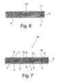
- Fig. 6 shows a conventional design of a joint 61 between the first core material 4 and the second core material 5.
- the joint 61 is formed in one part that is linear and runs from the front plate 2 to the back plate 3 at an angle of 90 degrees in relation to the front plate 2 and the back plate 3.
- Fig. 7 shows a sandwich panel 70 with different types of core joints 71, 72, 73, 74 between parts of core materials 4, 5 where each of the. core joints 71, 72, 73, 74 is provided with at least one reinforcing patch 9.
- Example 1 Finite Element Analysis of the stresses in the vicinity of joints of different core materials in sandwich panels
- the sandwich panel shown in Fig. 8 consists of two aluminium face plates and two types of PVC core materials, i.e. Divinycell H60 and Divinycell H200 (DIAB AB Group).
- Divinycell H60 constitutes the middle part of the panel, while Divinycell H200 constitutes its edges.
- the mechanical characteristics of the panel constituents are given in the table below. Modulus of elasticity of aluminium face plates 70 GPa Modulus of elasticity of a softer core, Divinycell H60 60 MPa Modulus of elasticity of a stiffer core, Divinycell H200 290 MPa
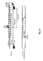
- Fig. 8 Various shapes of the core joints are considered as illustrated in Fig. 8. They are a conventional 90 degrees joint as well as circular, 45° and V-formed joints.
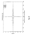
- Fig. 9 illustrates calculated stresses in the upper loaded (front) and lower (back) face plates in the vicinity of the joint situated at a distance of 120 mm from the loading point. Note that the front face is in compression (lower family of curves in Fig. 9) and the back face is in tension.
- transverse normal stresses in the core constitute a very critical point in the sandwich panel because they may initiate a delamination of the face plate and the core, which will jeopardize the integrity of the structure.
- the shape of the joint has a very large effect on the maximum value of the normal stresses in the core, as illustrated in Fig. 10.
- Both a wedge joint of 26.6 degrees and a circular joint allow the maximum value of ⁇ yy to be no larger than 0.5 MPa, which is 7 times smaller than the maximum stress of 3.6 MPa in the conventional 90 degrees joint.
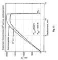
- Example 2 Experimental study of the maximum strength of sandwich panels with 90 degrees joints and sandwich panels with reinforcing patches in the joints
- Divinycell H60 constitute the middle part of the panel, while Divinycell H200 (DIAB AB Group) makes up its edges.
- Araldite® 2000 Two-component epoxy resin adhesive system Araldite® 2000 (Huntsman Advanced Materials) was used both for the attachment of the face plates to the core, and for adjoining different core materials at the joints.
- Reinforcing patches were produced by machining segment-like grooves at the joints and by filling them with the same adhesive.
- the maximum critical load for the panel with reinforced joints is approximately 10% higher than is the case for a conventional panel
- junction is a vulnerable element in a sandwich structure, but it can be reinforced by simple local strengthening of the faces at the spots neighbouring the core joints.
- the polymer-based fibre-reinforced materials mentioned are provided by a large number of different manufactures under a very large number of names and trade marks.
- the aforementioned fibrous composite materials systems can be manufactured using several fundamentally different manufacturing/processing techniques including hand lay-up, prepreg technology and various resin moulding transfer (RTM) and vacuum-assisted resin moulding transfer (VARTM) techniques.
- Structural adhesive materials systems are provided from a very large number of manufacturers that produce and market an even larger number of commercial adhesive systems based on many different polymers systems and technologies.
Priority Applications (4)
| Application Number | Priority Date | Filing Date | Title |
|---|---|---|---|
| EP03027020A EP1533433A1 (fr) | 2003-11-24 | 2003-11-24 | Panneau sandwich et procédé de sa fabrication |
| CA002547090A CA2547090A1 (fr) | 2003-11-24 | 2004-11-24 | Panneau en sandwich et procede de fabrication |
| US10/580,421 US20070264472A1 (en) | 2003-11-24 | 2004-11-24 | Sandwich Panel and a Method of Producing a Sandwich Panel |
| PCT/DK2004/000813 WO2005049933A1 (fr) | 2003-11-24 | 2004-11-24 | Panneau en sandwich et procede de fabrication |
Applications Claiming Priority (1)
| Application Number | Priority Date | Filing Date | Title |
|---|---|---|---|
| EP03027020A EP1533433A1 (fr) | 2003-11-24 | 2003-11-24 | Panneau sandwich et procédé de sa fabrication |
Publications (1)
| Publication Number | Publication Date |
|---|---|
| EP1533433A1 true EP1533433A1 (fr) | 2005-05-25 |
Family
ID=34429430
Family Applications (1)
| Application Number | Title | Priority Date | Filing Date |
|---|---|---|---|
| EP03027020A Withdrawn EP1533433A1 (fr) | 2003-11-24 | 2003-11-24 | Panneau sandwich et procédé de sa fabrication |
Country Status (4)
| Country | Link |
|---|---|
| US (1) | US20070264472A1 (fr) |
| EP (1) | EP1533433A1 (fr) |
| CA (1) | CA2547090A1 (fr) |
| WO (1) | WO2005049933A1 (fr) |
Cited By (6)
| Publication number | Priority date | Publication date | Assignee | Title |
|---|---|---|---|---|
| CN101743116A (zh) * | 2007-07-13 | 2010-06-16 | 赢创罗姆有限责任公司 | 用于芯材料的改进的对接接头 |
| US20110203718A1 (en) * | 2010-02-24 | 2011-08-25 | Eurocopter | Method of fabricating a honeycomb structured panel |
| RU2507352C1 (ru) * | 2012-06-18 | 2014-02-20 | Министерство промышленности и торговли Российской Федерации (Минпромторг России) | Панель среднего слоя и способ ее получения |
| RU2507071C1 (ru) * | 2012-06-18 | 2014-02-20 | Министерство промышленности и торговли Российской Федерации (Минпромторг России) | Способ получения трехслойного полимерного композиционного материала (тспкм) |
| ITRM20130211A1 (it) * | 2013-04-09 | 2014-10-10 | Iacobucci Hf Electronics S P A | Pannello composito per carrello portavivande e relativo carrello |
| EP2108837A3 (fr) * | 2008-02-27 | 2016-07-27 | General Electric Company | Tour d'éolienne composite |
Families Citing this family (10)
| Publication number | Priority date | Publication date | Assignee | Title |
|---|---|---|---|---|
| DE10336359B4 (de) * | 2003-08-08 | 2007-01-04 | Saint-Gobain Glass Deutschland Gmbh | Plattenförmiges Verbundelement mit einer Lagesicherung für eine Klebeverbindung |
| DE102007003275B4 (de) * | 2007-01-23 | 2013-11-28 | Airbus Operations Gmbh | Schalenelement als Teil eines Flugzeugrumpfes |
| US20090297780A1 (en) * | 2009-06-03 | 2009-12-03 | Nia Chiou Yiu Industrial Co., Ltd. | Water-proof wood board |
| ES2385906B1 (es) * | 2009-09-30 | 2013-06-17 | Airbus Operations, S.L. | Disposición de unión circunferencial de elementos estructurales con un elemento de acoplamiento realizado en material compuesto. |
| US10252490B2 (en) * | 2011-07-18 | 2019-04-09 | Rilco Manufacturing Company, Inc. | Method and system for reinforced pipe insulation |
| CN103748009B (zh) * | 2011-08-17 | 2016-05-11 | B/E航空公司 | 具有嵌入式插入件的高强度航空器内部板部件 |
| FR3003233B1 (fr) * | 2013-03-18 | 2016-05-06 | Airbus Operations Sas | Panneau de voilure pour aeronef |
| GB201322275D0 (en) * | 2013-12-17 | 2014-01-29 | Rolls Royce Plc | A Laminated composite structure and related method |
| MX2017016407A (es) * | 2015-07-23 | 2018-03-02 | Composites Intellectual Holdings Inc | Sistema de union de estructuras de material compuesto y metodo y estructuras relacionadas. |
| US20200377191A1 (en) * | 2019-05-29 | 2020-12-03 | The Boeing Company | Stringerless sandwich fuselage panels |
Citations (5)
| Publication number | Priority date | Publication date | Assignee | Title |
|---|---|---|---|---|
| US2578781A (en) * | 1945-01-18 | 1951-12-18 | Brundige Roy Samuel | Manufacture of plywood |
| US3709733A (en) * | 1970-06-26 | 1973-01-09 | Craig Syst Corp | Composite panel structure having mounting inserts therein |
| US4093762A (en) * | 1974-04-30 | 1978-06-06 | John Kiefer | Method of making a hardcore honeycomb panel and honeycomb panel made thereby |
| US4411939A (en) * | 1979-11-28 | 1983-10-25 | National Research Development Corporation | Conformable reinforcement board |
| US5589243A (en) * | 1992-05-04 | 1996-12-31 | Webcore Technologies, Inc. | Reinforced foam cores and method and apparatus of production |
Family Cites Families (2)
| Publication number | Priority date | Publication date | Assignee | Title |
|---|---|---|---|---|
| DK122829B (da) * | 1970-05-01 | 1972-04-17 | P Bruun | Samling af mindst to bygningsdele samt fremgangsmåde til fremstilling af denne samling. |
| US4223053A (en) * | 1978-08-07 | 1980-09-16 | The Boeing Company | Truss core panels |
-
2003
- 2003-11-24 EP EP03027020A patent/EP1533433A1/fr not_active Withdrawn
-
2004
- 2004-11-24 US US10/580,421 patent/US20070264472A1/en not_active Abandoned
- 2004-11-24 CA CA002547090A patent/CA2547090A1/fr not_active Abandoned
- 2004-11-24 WO PCT/DK2004/000813 patent/WO2005049933A1/fr active Application Filing
Patent Citations (5)
| Publication number | Priority date | Publication date | Assignee | Title |
|---|---|---|---|---|
| US2578781A (en) * | 1945-01-18 | 1951-12-18 | Brundige Roy Samuel | Manufacture of plywood |
| US3709733A (en) * | 1970-06-26 | 1973-01-09 | Craig Syst Corp | Composite panel structure having mounting inserts therein |
| US4093762A (en) * | 1974-04-30 | 1978-06-06 | John Kiefer | Method of making a hardcore honeycomb panel and honeycomb panel made thereby |
| US4411939A (en) * | 1979-11-28 | 1983-10-25 | National Research Development Corporation | Conformable reinforcement board |
| US5589243A (en) * | 1992-05-04 | 1996-12-31 | Webcore Technologies, Inc. | Reinforced foam cores and method and apparatus of production |
Cited By (10)
| Publication number | Priority date | Publication date | Assignee | Title |
|---|---|---|---|---|
| CN101743116A (zh) * | 2007-07-13 | 2010-06-16 | 赢创罗姆有限责任公司 | 用于芯材料的改进的对接接头 |
| US20100189954A1 (en) * | 2007-07-13 | 2010-07-29 | Evonik Roehm Gmbh | Butt joint connections for core materials |
| EP2176056B1 (fr) * | 2007-07-13 | 2015-08-05 | Evonik Röhm GmbH | Soudures bout à bout améliorées pour matériaux d'âme |
| EP2108837A3 (fr) * | 2008-02-27 | 2016-07-27 | General Electric Company | Tour d'éolienne composite |
| US20110203718A1 (en) * | 2010-02-24 | 2011-08-25 | Eurocopter | Method of fabricating a honeycomb structured panel |
| US8377244B2 (en) * | 2010-02-24 | 2013-02-19 | Eurocopter | Method of fabricating a honeycomb structured panel |
| RU2507352C1 (ru) * | 2012-06-18 | 2014-02-20 | Министерство промышленности и торговли Российской Федерации (Минпромторг России) | Панель среднего слоя и способ ее получения |
| RU2507071C1 (ru) * | 2012-06-18 | 2014-02-20 | Министерство промышленности и торговли Российской Федерации (Минпромторг России) | Способ получения трехслойного полимерного композиционного материала (тспкм) |
| ITRM20130211A1 (it) * | 2013-04-09 | 2014-10-10 | Iacobucci Hf Electronics S P A | Pannello composito per carrello portavivande e relativo carrello |
| WO2014167593A3 (fr) * | 2013-04-09 | 2015-09-24 | Iacobucci Hf Aerospace S.P.A. | Dispositif de fermeture pour équipements aéronautiques, tels que des chariots ayant des panneaux composites ultralégers |
Also Published As
| Publication number | Publication date |
|---|---|
| WO2005049933A1 (fr) | 2005-06-02 |
| US20070264472A1 (en) | 2007-11-15 |
| CA2547090A1 (fr) | 2005-06-02 |
Similar Documents
| Publication | Publication Date | Title |
|---|---|---|
| US9592650B2 (en) | Composite laminate including beta-reinforcing fibers | |
| EP1533433A1 (fr) | Panneau sandwich et procédé de sa fabrication | |
| Cao et al. | Design and testing of joints for composite sandwich/steel hybrid ship hulls | |
| KR102047554B1 (ko) | 복합재 햇 보강재, 복합재 햇-보강 압력 웨브, 및 그 제조 방법 | |
| US10391734B2 (en) | Composite sandwich panel with differential resin layers | |
| EP2026962B1 (fr) | Stratifie de feuilles de metal et polymere | |
| EP2142360B1 (fr) | Structure composite comprenant une lisse avec un bloc incorporé dans le creux d'un panneau et procédé de transmission de forces | |
| US20100133380A1 (en) | Skin panel for an aircraft fuselage | |
| EP2014437A1 (fr) | Procede de moulage d'un element structurel en materiau composite et element structurel en materiau composite | |
| JP2016064646A (ja) | 補強プレート間の複合材梁弦材、及び関連する製造方法 | |
| EP0293320A2 (fr) | Jonction de composites sur deux niveaux | |
| JP2944967B2 (ja) | 高速車両の外壁構造および高速車両の外壁の製造方法 | |
| EP4129637A1 (fr) | Élément pour renforcement de prv, son procédé de production, corps moulé en prv et structure de raccordement de prv | |
| WO2019219662A1 (fr) | Joint composite |
Legal Events
| Date | Code | Title | Description |
|---|---|---|---|
| PUAI | Public reference made under article 153(3) epc to a published international application that has entered the european phase |
Free format text: ORIGINAL CODE: 0009012 |
|
| AK | Designated contracting states |
Kind code of ref document: A1 Designated state(s): AT BE BG CH CY CZ DE DK EE ES FI FR GB GR HU IE IT LI LU MC NL PT RO SE SI SK TR |
|
| AX | Request for extension of the european patent |
Extension state: AL LT LV MK |
|
| 17P | Request for examination filed |
Effective date: 20051125 |
|
| AKX | Designation fees paid |
Designated state(s): AT BE BG CH CY CZ DE DK EE ES FI FR GB GR HU IE IT LI LU MC NL PT RO SE SI SK TR |
|
| STAA | Information on the status of an ep patent application or granted ep patent |
Free format text: STATUS: THE APPLICATION IS DEEMED TO BE WITHDRAWN |
|
| 18D | Application deemed to be withdrawn |
Effective date: 20061121 |