EP1533215B1 - Dossier dos pour motocyclette - Google Patents
Dossier dos pour motocyclette Download PDFInfo
- Publication number
- EP1533215B1 EP1533215B1 EP03257389A EP03257389A EP1533215B1 EP 1533215 B1 EP1533215 B1 EP 1533215B1 EP 03257389 A EP03257389 A EP 03257389A EP 03257389 A EP03257389 A EP 03257389A EP 1533215 B1 EP1533215 B1 EP 1533215B1
- Authority
- EP
- European Patent Office
- Prior art keywords
- vehicle seat
- motor vehicle
- right sliding
- sliding rails
- rod
- Prior art date
- Legal status (The legal status is an assumption and is not a legal conclusion. Google has not performed a legal analysis and makes no representation as to the accuracy of the status listed.)
- Expired - Lifetime
Links
- 230000006835 compression Effects 0.000 claims description 7
- 238000007906 compression Methods 0.000 claims description 7
- 230000000717 retained effect Effects 0.000 abstract 1
- 230000001419 dependent effect Effects 0.000 description 1
Images


Classifications
-
- B—PERFORMING OPERATIONS; TRANSPORTING
- B62—LAND VEHICLES FOR TRAVELLING OTHERWISE THAN ON RAILS
- B62J—CYCLE SADDLES OR SEATS; AUXILIARY DEVICES OR ACCESSORIES SPECIALLY ADAPTED TO CYCLES AND NOT OTHERWISE PROVIDED FOR, e.g. ARTICLE CARRIERS OR CYCLE PROTECTORS
- B62J1/00—Saddles or other seats for cycles; Arrangement thereof; Component parts
- B62J1/12—Box-shaped seats; Bench-type seats, e.g. dual or twin seats
-
- B—PERFORMING OPERATIONS; TRANSPORTING
- B62—LAND VEHICLES FOR TRAVELLING OTHERWISE THAN ON RAILS
- B62J—CYCLE SADDLES OR SEATS; AUXILIARY DEVICES OR ACCESSORIES SPECIALLY ADAPTED TO CYCLES AND NOT OTHERWISE PROVIDED FOR, e.g. ARTICLE CARRIERS OR CYCLE PROTECTORS
- B62J1/00—Saddles or other seats for cycles; Arrangement thereof; Component parts
- B62J1/28—Other additional equipment, e.g. back-rests for children
Definitions
- This invention relates to a back-supporting device for a motor vehicle seat, and more particularly to a back-supporting device for a motor vehicle seat that includes a backrest which is movable on the seat.
- a conventional motorcycle seat is shown to include a driver seat portion, a passenger seat portion, a luggage frame, and a backrest fixed on the luggage frame and disposed immediately behind the passenger seat portion. As such, the backrest cannot be used to support a driver's back.
- US 3,822,917 discloses an adjustable back-supporting device for a motor vehicle seat, the back-supporting device comprising two slide rails, means for mounting the slide rails on the sides of the vehicle seat, two slide units slidably mounted on the respective slide rails and carrying respective upwardly-extending supporting frames, a backrest mounted on the upper ends of the supporting frames, and means for locking the slide units in at least one forward and at least one rearward position on said slide rails.
- the present invention provides an adjustable back-supporting device as summarised above, characterised in that said slide rails converge and in that means are provided for allowing transverse movement of the supporting frames relative to the backrest to accommodate the convergence of the slide rails.
- the invention further provides a motor vehicle seat having a driver seat portion disposed at a front portion of the motor vehicle seat, a passenger seat portion disposed immediately behind the driver seat portion, the width of the passenger seat portion reducing gradually from the front end to the rear end thereof, the motor vehicle seat having an adjustable back-supporting device as defined above, the slide rails of said back-supporting device being mounted on the sides of the vehicle seat.
- a back supporting device 5 according to this invention is shown to include a pair of hollow left and right sliding rails 51, 52, two slide units 53, two supporting frames 54, a back supporting mechanism 55, and two locking units in the form of lock bolts 56.
- the back supporting device 5 is mounted on a motor vehicle seat 3 that is configured as a motorcycle seat and that has a driver seat portion 31 disposed at a front portion of the motor vehicle seat 3, and a passenger seat portion 32 disposed immediately behind the driver seat portion 31.
- the passenger seat portion 32 has a width that is reduced gradually from a front end thereof to a rear end thereof.
- the left and right sliding rails 51, 52 are disposed respectively and fixedly on two opposite sides of the passenger seat portion 32, extend from the front end of the passenger seat portion 32 to the rear end of the passenger seat portion 32, and are spaced apart from each other by a distance along a transverse direction (t) (see Fig. 1) of the motor vehicle seat 3. The distance is reduced gradually from the front end of the passenger seat portion 32 to the rear end of the passenger seat portion 32, as shown in Fig. 1.
- Each of the left and right sliding rails 51, 52 has a top surface that is formed with a longitudinal row of positioning holes 511, 521, is shaped as a rectangular tube, and has an outer sidewall that is formed with a longitudinal slot 512, 522 therethrough.
- Each of the slide units 53 includes a slidable element 531 received movably within a corresponding one of the left and right sliding rails 51, 52, a connecting member 532 disposed outwardly of the corresponding one of the left and right sliding rails 51, 52 and connected fixedly to the slidable element 531 by the corresponding lock bolt 56, and a positioning unit for retaining the slidable element 531 at a selected one of a plurality of positions relative to the corresponding one of the left and right sliding rails 51, 52.
- the slidable elements 531 are also shaped as rectangular tubes received respectively and fittingly within the left and right sliding rails 51, 52.
- Each of the slidable elements 531 of the slide units 53 has an outer sidewall that is formed with a threaded hole 531' therethrough.
- the lock bolts 56 extend respectively through the longitudinal slots 512, 522 in the left and right sliding rails 51, 52, and engage respectively the threaded holes 531' in the slidable elements 531 so as to lock the slidable elements 531 respectively and releasably within the left and right sliding rails 51, 52.
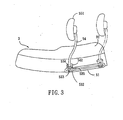
- Each of the positioning units of the slide units 53 includes a positioning member 533 connected pivotally to the connecting member 532 of the corresponding slide unit 53, and a biasing unit that is configured as a coiled tension spring 535.
- Each of the positioning members 533 is shaped as a curved rod, and includes a zigzag rod portion 534 (see Fig. 5) connected pivotally to the connecting member 532 of the corresponding slide unit 53, and an insert portion 536 (see Figs. 4 and 5) that is shaped as an L-shaped rod and that is connected fixedly to a front end of the zigzag rod portion 534.
- Each of the coiled tension springs 535 has a front end fastened to a rear end of the corresponding zigzag rod portion 534, and a rear end disposed above the front end of the corresponding coiled tension spring 535 and fastened to the connecting member 532 of the corresponding slide unit 53, as shown in Fig. 3.
- the insert portions 536 of the positioning members 533 are biased by the coiled tension springs 535 to turn downwardly so as to engage respectively two selected ones of the positioning holes 511, 521 in the top surfaces of the left and right sliding rails 51, 52.
- Each of the supporting frames 54 has a curved rod body 541, an inverted T-shaped lower end 542 that is formed integrally with the curved rod body 541 and that is connected pivotally to the connecting member 532 of the corresponding slide unit 53 such that upper ends of the supporting frames 54 can rotate toward and away from each other, and an upper end 541' that is C-shaped and that defines a curved groove 543.
- the curved grooves 543 are located between the upper ends 541' of the supporting frames 54.
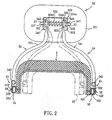
- the back supporting mechanism 55 includes a backrest 551 mounted to the supporting frames 54 and disposed above the passenger seat portion 32, and a frame-positioning device 552 disposed between the backrest 551 and the supporting frames 54 to position the backrest 551 on the supporting frames 54.
- a frame-positioning device 552 disposed between the backrest 551 and the supporting frames 54 to position the backrest 551 on the supporting frames 54.
- the frame-positioning device 552 includes an inverted U-shaped wall 553, a horizontal rod 557, a coiled compression spring 558, and two pressing elements 559.
- the inverted U-shaped wall 553 is mounted fixedly on the backrest 551, and has two parallel rod-supporting wall portions (553a).
- the horizontal rod 557 extends through holes 555 in the rod-supporting wall portions (553a) of the inverted U-shaped wall 553.
- Two retaining rings 57 are sleeved respectively and fixedly around two ends of the horizontal rod 557, and abut against the rod-supporting wall portions (553a) of the inverted U-shaped wall 553 so as to fix the horizontal rod 557 relative to the inverted U-shaped wall 553.
- the upper ends 541' of the supporting frames 54 are sleeved movably and rotatably on the horizontal rod 557 between the rod-supporting wall portions (553a) of the inverted U-shaped wall 553.
- the coiled compression spring 558 is sleeved around the horizontal rod 557 between the upper ends 541' of the supporting frames 54.
- Each of the pressing elements 559 is sleeved movably and rotatably around the horizontal rod 557 between the upper end 541' of the corresponding supporting frame 54 and the coiled compression spring 558, and has a semi-spherical outer portion 5591 that engages fittingly the curved groove 543 in the upper end 541' of the corresponding supporting frame 54, and a circular tubular inner portion 5592 that is formed integrally with the semi-spherical outer portion 5591.
- the coiled compression spring 558 has two ends that are sleeved respectively around the circular tubular inner portions 5592 of the pressing elements 559 and that press the semi-spherical outer portions 5591 of the pressing elements 559 and the upper ends 541' of the supporting frames 54 against the rod-supporting wall portions (553a) of the inverted U-shaped wall 553.
- the upper ends 541' of the supporting frames 54 are positioned within the inverted U-shaped wall 553 such that the supporting frames 54 can be pivoted between an outer position shown by solid lines in Fig. 2 (corresponding to a forward position of the back supporting device) on the passenger seat and an inner position shown by phantom lines in Fig. 2 (corresponding to a rearward position of the back supporting device).
- the back supporting device can be moved forcibly between the forward and rearward positions.
- the back supporting device can be provided in partially or totally disassembled form as a kit of parts.
Landscapes
- Engineering & Computer Science (AREA)
- Mechanical Engineering (AREA)
- Seats For Vehicles (AREA)
- Polishing Bodies And Polishing Tools (AREA)
- Ceramic Products (AREA)
Claims (8)
- Dossier réglable destiné à un siège de véhicule à moteur (3), le dossier comprenant deux rails de guidage (51, 52), des moyens pour monter les rails de guidage sur les côtés du siège de véhicule, deux unités de glissière (53) montées de manière coulissante sur les rails de guidage respectifs et supportant des châssis de support (54) respectifs s'étendant vers le haut, un dossier rembourré (551) monté sur les extrémités supérieures des châssis de support, et des moyens (561, 511) pour bloquer les unités de glissière dans au moins une position avant et une position arrière sur lesdits rails de guidage, caractérisé en ce que lesdits rails de guidage (51, 52) convergent et en ce que l'on prévoit des moyens (557, 5591) pour permettre le mouvement transversal des châssis de support (54) par rapport au dossier rembourré (551) pour accepter la convergence des rails de guidage.
- Siège (3) de véhicule à moteur doté d'une partie de siège de conducteur (31) disposée au niveau d'une partie avant du siège (3) de véhicule à moteur, une partie de siège de passager (32) disposée immédiatement derrière la partie de siège de conducteur (31), la largeur de la partie de siège de passager (32) réduisant progressivement de l'extrémité avant à son extrémité arrière, le siège de véhicule à moteur ayant un dossier réglable (5) selon la revendication 1, les rails de guidage (51, 52) dudit dossier étant montés sur les côtés du siège de véhicule.
- Siège (3) de véhicule à moteur selon la revendication 2, caractérisé en outre en ce qu'il comprend deux unités de blocage pour bloquer les éléments coulissants (531) respectifs de manière amovible dans les rails de guidage gauche et droit (51, 52) afin de fixer le dossier rembourré (551) sur le siège (3) de véhicule à moteur.
- Siège (3) de véhicule à moteur selon la revendication 3, caractérisé en ce outre en ce que chacun des rails de guidage gauche et droit (51, 52) est formé comme un tube rectangulaire et a une paroi latérale externe qui est formée avec une fente longitudinale (512, 522) à travers celle-ci, les éléments coulissants (531) étant également formés comme des tubes rectangulaires qui sont montés dans les rails de guidage gauche et droit (51, 52) respectivement, chacun des éléments coulissants (531) ayant une paroi latérale externe qui est formée avec un trou fileté (531') à travers celle-ci et en ce que les unités de blocage sont deux boulons de blocage (56) qui s'étendent à travers les fentes longitudinales (512, 522) respectives dans les rails de guidage gauche et droit (51, 52) et qui mettent en prise les trous filetés (531') respectifs dans les éléments coulissants (531) afin de bloquer les éléments coulissants (531) respectifs de manière amovible dans les rails de guidage gauche et droit (51, 52), moyennant quoi les boulons de blocage (56) sont desserrés, les éléments coulissants (531) peuvent se déplacer dans les rails de guidage gauche et droit (51, 52) respectifs.
- Siège (3) de véhicule à moteur selon l'une quelconque des revendications 2 à 4, caractérisé en outre en ce que chacun des rails de guidage gauche et droit (51, 52) a une surface supérieure qui est formée avec une rangée longitudinale de trous de positionnement (511, 521), chacun des trous de positionnement, comprenant :un élément de positionnement (533) raccordé de manière pivotante à un élément correspondant des éléments de raccordement (532) des unités de glissière (53) et ayant une partie d'insertion fixe (536) ; etune unité de rappel pour solliciter la partie d'insertion (536) de l'élément de positionnement (533) pour mettre en prise un trou sélectionné des trous de positionnement (511, 521) dans un rail correspondant des rails de guidage gauche et droit (51, 52) afin de retenir un élément correspondant des éléments coulissants (531) au niveau de la position sélectionnée des positions par rapport au rail correspondant des rails de guidage gauche et droit (51, 52).
- Siège (3) de véhicule à moteur selon la revendication 5, caractérisé en outre en ce que chacun des éléments de positionnement (533) est formé comme une tige incurvée, et comprend en outre une partie de tige de zigzag (534) raccordée de manière pivotante à l'élément correspondant des éléments de raccordement (532) des unités de glissière (53), chacune des parties d'insertion (536) des éléments de positionnement (533) se présentant sous la forme d'une tige en forme de L et étant raccordée de manière fixe à une extrémité d'une partie correspondante des parties de tige en zigzag (534), chacune des unités de rappel des unités de positionnement étant configurée comme un ressort hélicoïdal de tension (535) qui a deux extrémités qui sont fixées respectivement sur l'autre extrémité de la partie correspondante des parties de tige en zigzag (534) et de l'élément correspondant des éléments de raccordement (532) des unités de glissière (53).
- Siège (3) de véhicule à moteur selon l'une quelconque des revendications 2 à 6, caractérisé en ce que le dispositif de positionnement de châssis (552) comprend :une paroi en forme de U inversé (553) montée de manière fixe sur le dossier rembourré (551) et ayant deux parties de paroi de support de tige (553a) parallèles ;une tige horizontale (557) s'étendant à travers et raccordée de manière fixe aux parties de paroi de support de tige (553a) de la paroi en forme de U inversé (553), les extrémités supérieures (541') des châssis de support (54) étant rapportées de manière mobile et rotative sur la tige horizontale (557) entre les parties de paroi de support de tige (553a) de la paroi en forme de U inversé (553) ; etun ressort hélicoïdal de compression (558) rapporté autour de la tige horizontale (557) entre les extrémités supérieures (541') des châssis de support (54) afin de comprimer les extrémités supérieures (541') des châssis de support (54) respectivement contre les parties de paroi de support de tige (553a) de la paroi en forme de U inversé (553).
- Siège (3) de véhicule à moteur selon la revendication 7, caractérisé en outre en ce que chacune des extrémités supérieures (541') des châssis de support (54) est en forme de C, et définit une rainure incurvée (543), les rainures incurvées (543) dans les extrémités supérieures (541') étant situées entre les extrémités supérieures (541') des châssis de support (54), le dispositif de positionnement de châssis (552) comprenant en outre deux éléments de compression (559), dont chacun est rapporté de manière mobile et rotative autour de la tige horizontale (557) entre l'extrémité supérieure (541') d'un châssis respectif des châssis de support (54) et le ressort hélicoïdal de compression (558), chacun des éléments de compression (559) ayant une partie externe semi sphérique (5591) qui met convenablement en prise la rainure incurvée (543) dans l'extrémité supérieure (541') du châssis respectif des châssis de support (54), et une partie interne tubulaire circulaire (5592) qui est formée de manière solidaire avec la partie externe semi sphérique (5591), le ressort hélicoïdal de compression (558) ayant deux extrémités qui sont rapportées autour des parties internes tubulaires circulaires (5592) respectives des éléments de compression (559) et qui sont comprimées contre les parties externes semi sphériques (5591) respectives des éléments de compression (559).
Priority Applications (4)
| Application Number | Priority Date | Filing Date | Title |
|---|---|---|---|
| ES03257389T ES2256681T3 (es) | 2003-11-24 | 2003-11-24 | Dispositivo de apoyo trasero para un asiento de vehiculo de motor. |
| AT03257389T ATE314245T1 (de) | 2003-11-24 | 2003-11-24 | Rückenstütze für ein motorrad |
| EP03257389A EP1533215B1 (fr) | 2003-11-24 | 2003-11-24 | Dossier dos pour motocyclette |
| DE60303042T DE60303042T2 (de) | 2003-11-24 | 2003-11-24 | Rückenstütze für ein Motorrad |
Applications Claiming Priority (1)
| Application Number | Priority Date | Filing Date | Title |
|---|---|---|---|
| EP03257389A EP1533215B1 (fr) | 2003-11-24 | 2003-11-24 | Dossier dos pour motocyclette |
Publications (2)
| Publication Number | Publication Date |
|---|---|
| EP1533215A1 EP1533215A1 (fr) | 2005-05-25 |
| EP1533215B1 true EP1533215B1 (fr) | 2005-12-28 |
Family
ID=34429539
Family Applications (1)
| Application Number | Title | Priority Date | Filing Date |
|---|---|---|---|
| EP03257389A Expired - Lifetime EP1533215B1 (fr) | 2003-11-24 | 2003-11-24 | Dossier dos pour motocyclette |
Country Status (4)
| Country | Link |
|---|---|
| EP (1) | EP1533215B1 (fr) |
| AT (1) | ATE314245T1 (fr) |
| DE (1) | DE60303042T2 (fr) |
| ES (1) | ES2256681T3 (fr) |
Families Citing this family (2)
| Publication number | Priority date | Publication date | Assignee | Title |
|---|---|---|---|---|
| DE102018202515A1 (de) * | 2018-02-20 | 2019-08-22 | Bayerische Motoren Werke Aktiengesellschaft | Sitzbaugruppe für ein Kraftrad |
| CN115534781B (zh) * | 2022-10-21 | 2025-05-23 | 重庆骏普康实业有限公司 | 一种装配式座椅骨架总成 |
Family Cites Families (6)
| Publication number | Priority date | Publication date | Assignee | Title |
|---|---|---|---|---|
| US3822917A (en) * | 1972-05-22 | 1974-07-09 | S George | Adjustable backrest for a seat for cycles |
| US4030750A (en) * | 1975-02-28 | 1977-06-21 | Doug Abram | Sissy bar for a motorcycle |
| US4032189A (en) * | 1976-06-21 | 1977-06-28 | Vicente Cruz Benavente | Motorcycle back rest assembly |
| US5026119A (en) * | 1984-09-27 | 1991-06-25 | Frank Harvey A | Back support for motorcycles |
| US5441330A (en) * | 1991-11-25 | 1995-08-15 | Rojas; Libardo | Back support for motorcycles |
| US5518291A (en) * | 1994-05-03 | 1996-05-21 | Shaide; Ron | Removable and adjustable backrest and storage compartment for a motorcycle, scooter, moped or other vehicle |
-
2003
- 2003-11-24 DE DE60303042T patent/DE60303042T2/de not_active Expired - Lifetime
- 2003-11-24 EP EP03257389A patent/EP1533215B1/fr not_active Expired - Lifetime
- 2003-11-24 AT AT03257389T patent/ATE314245T1/de not_active IP Right Cessation
- 2003-11-24 ES ES03257389T patent/ES2256681T3/es not_active Expired - Lifetime
Also Published As
| Publication number | Publication date |
|---|---|
| EP1533215A1 (fr) | 2005-05-25 |
| ATE314245T1 (de) | 2006-01-15 |
| DE60303042D1 (de) | 2006-02-02 |
| ES2256681T3 (es) | 2006-07-16 |
| DE60303042T2 (de) | 2006-08-24 |
Similar Documents
| Publication | Publication Date | Title |
|---|---|---|
| US6910740B2 (en) | Articulated headrestraint system | |
| US6644525B1 (en) | Hitch rack | |
| CN102271990B (zh) | 具有用于乘客的设置的全地形车 | |
| US5895094A (en) | Headrest apparatus for vehicle seat | |
| US5348261A (en) | Low mass manual two-way seat adjuster | |
| US6568699B2 (en) | Adjustable sissy bar mechanism for use with a motorcycle | |
| US7073854B2 (en) | Back supporting device for a motor vehicle seat | |
| US4606578A (en) | Head-rest | |
| JPH10138811A (ja) | 乗物用ヘッドレスト装置 | |
| US7900801B2 (en) | Multi-function vehicle-carrying frame | |
| WO2021001853A1 (fr) | Repose-pied rétractable de véhicule | |
| US7192042B2 (en) | Adjustable seating system | |
| EP1533215B1 (fr) | Dossier dos pour motocyclette | |
| US6330994B1 (en) | Adjustable support apparatus and architecture for adjusting support apparatus | |
| US20030057674A1 (en) | Bicycle sidecar | |
| EP1717137A1 (fr) | Support postérieur mobile pour une motocyclette | |
| CN114789683B (zh) | 安全座椅及其底座 | |
| US7360819B1 (en) | Quick-release motorcycle windshield | |
| CN210235168U (zh) | 一种电动车自行车上可滑动调节的坐垫组件 | |
| CN218558640U (zh) | 一种后排座椅骨架 | |
| EP1167116A1 (fr) | Dossier de siège de véhicule | |
| CN221233940U (zh) | 座椅装置及自行车 | |
| CN116923602B (zh) | 长度可调整的摩托车 | |
| CN212267725U (zh) | 方向把可前后调节式电动自行车 | |
| RU238251U1 (ru) | Складное сиденье транспортного средства |
Legal Events
| Date | Code | Title | Description |
|---|---|---|---|
| PUAI | Public reference made under article 153(3) epc to a published international application that has entered the european phase |
Free format text: ORIGINAL CODE: 0009012 |
|
| 17P | Request for examination filed |
Effective date: 20040816 |
|
| AK | Designated contracting states |
Kind code of ref document: A1 Designated state(s): AT BE BG CH CY CZ DE DK EE ES FI FR GB GR HU IE IT LI LU MC NL PT RO SE SI SK TR |
|
| AX | Request for extension of the european patent |
Extension state: AL LT LV MK |
|
| GRAP | Despatch of communication of intention to grant a patent |
Free format text: ORIGINAL CODE: EPIDOSNIGR1 |
|
| GRAS | Grant fee paid |
Free format text: ORIGINAL CODE: EPIDOSNIGR3 |
|
| GRAA | (expected) grant |
Free format text: ORIGINAL CODE: 0009210 |
|
| AK | Designated contracting states |
Kind code of ref document: B1 Designated state(s): AT BE BG CH CY CZ DE DK EE ES FI FR GB GR HU IE IT LI LU MC NL PT RO SE SI SK TR |
|
| PG25 | Lapsed in a contracting state [announced via postgrant information from national office to epo] |
Ref country code: SI Free format text: LAPSE BECAUSE OF FAILURE TO SUBMIT A TRANSLATION OF THE DESCRIPTION OR TO PAY THE FEE WITHIN THE PRESCRIBED TIME-LIMIT Effective date: 20051228 Ref country code: IT Free format text: LAPSE BECAUSE OF FAILURE TO SUBMIT A TRANSLATION OF THE DESCRIPTION OR TO PAY THE FEE WITHIN THE PRESCRIBED TIME-LIMIT;WARNING: LAPSES OF ITALIAN PATENTS WITH EFFECTIVE DATE BEFORE 2007 MAY HAVE OCCURRED AT ANY TIME BEFORE 2007. THE CORRECT EFFECTIVE DATE MAY BE DIFFERENT FROM THE ONE RECORDED. Effective date: 20051228 Ref country code: SK Free format text: LAPSE BECAUSE OF FAILURE TO SUBMIT A TRANSLATION OF THE DESCRIPTION OR TO PAY THE FEE WITHIN THE PRESCRIBED TIME-LIMIT Effective date: 20051228 Ref country code: CZ Free format text: LAPSE BECAUSE OF FAILURE TO SUBMIT A TRANSLATION OF THE DESCRIPTION OR TO PAY THE FEE WITHIN THE PRESCRIBED TIME-LIMIT Effective date: 20051228 Ref country code: BE Free format text: LAPSE BECAUSE OF FAILURE TO SUBMIT A TRANSLATION OF THE DESCRIPTION OR TO PAY THE FEE WITHIN THE PRESCRIBED TIME-LIMIT Effective date: 20051228 Ref country code: LI Free format text: LAPSE BECAUSE OF FAILURE TO SUBMIT A TRANSLATION OF THE DESCRIPTION OR TO PAY THE FEE WITHIN THE PRESCRIBED TIME-LIMIT Effective date: 20051228 Ref country code: AT Free format text: LAPSE BECAUSE OF FAILURE TO SUBMIT A TRANSLATION OF THE DESCRIPTION OR TO PAY THE FEE WITHIN THE PRESCRIBED TIME-LIMIT Effective date: 20051228 Ref country code: CH Free format text: LAPSE BECAUSE OF FAILURE TO SUBMIT A TRANSLATION OF THE DESCRIPTION OR TO PAY THE FEE WITHIN THE PRESCRIBED TIME-LIMIT Effective date: 20051228 Ref country code: FI Free format text: LAPSE BECAUSE OF FAILURE TO SUBMIT A TRANSLATION OF THE DESCRIPTION OR TO PAY THE FEE WITHIN THE PRESCRIBED TIME-LIMIT Effective date: 20051228 Ref country code: NL Free format text: LAPSE BECAUSE OF FAILURE TO SUBMIT A TRANSLATION OF THE DESCRIPTION OR TO PAY THE FEE WITHIN THE PRESCRIBED TIME-LIMIT Effective date: 20051228 Ref country code: RO Free format text: LAPSE BECAUSE OF FAILURE TO SUBMIT A TRANSLATION OF THE DESCRIPTION OR TO PAY THE FEE WITHIN THE PRESCRIBED TIME-LIMIT Effective date: 20051228 |
|
| REG | Reference to a national code |
Ref country code: GB Ref legal event code: FG4D |
|
| REG | Reference to a national code |
Ref country code: CH Ref legal event code: EP |
|
| REG | Reference to a national code |
Ref country code: IE Ref legal event code: FG4D |
|
| REF | Corresponds to: |
Ref document number: 60303042 Country of ref document: DE Date of ref document: 20060202 Kind code of ref document: P |
|
| AKX | Designation fees paid |
Designated state(s): AT BE BG CH CY CZ DE DK EE ES FI FR GB GR HU IE IT LI LU MC NL PT RO SE SI SK TR |
|
| PG25 | Lapsed in a contracting state [announced via postgrant information from national office to epo] |
Ref country code: GR Free format text: LAPSE BECAUSE OF FAILURE TO SUBMIT A TRANSLATION OF THE DESCRIPTION OR TO PAY THE FEE WITHIN THE PRESCRIBED TIME-LIMIT Effective date: 20060328 Ref country code: BG Free format text: LAPSE BECAUSE OF FAILURE TO SUBMIT A TRANSLATION OF THE DESCRIPTION OR TO PAY THE FEE WITHIN THE PRESCRIBED TIME-LIMIT Effective date: 20060328 Ref country code: DK Free format text: LAPSE BECAUSE OF FAILURE TO SUBMIT A TRANSLATION OF THE DESCRIPTION OR TO PAY THE FEE WITHIN THE PRESCRIBED TIME-LIMIT Effective date: 20060328 Ref country code: SE Free format text: LAPSE BECAUSE OF FAILURE TO SUBMIT A TRANSLATION OF THE DESCRIPTION OR TO PAY THE FEE WITHIN THE PRESCRIBED TIME-LIMIT Effective date: 20060328 |
|
| PG25 | Lapsed in a contracting state [announced via postgrant information from national office to epo] |
Ref country code: PT Free format text: LAPSE BECAUSE OF FAILURE TO SUBMIT A TRANSLATION OF THE DESCRIPTION OR TO PAY THE FEE WITHIN THE PRESCRIBED TIME-LIMIT Effective date: 20060529 |
|
| NLV1 | Nl: lapsed or annulled due to failure to fulfill the requirements of art. 29p and 29m of the patents act | ||
| PG25 | Lapsed in a contracting state [announced via postgrant information from national office to epo] |
Ref country code: HU Free format text: LAPSE BECAUSE OF FAILURE TO SUBMIT A TRANSLATION OF THE DESCRIPTION OR TO PAY THE FEE WITHIN THE PRESCRIBED TIME-LIMIT Effective date: 20060629 |
|
| REG | Reference to a national code |
Ref country code: CH Ref legal event code: PL |
|
| REG | Reference to a national code |
Ref country code: ES Ref legal event code: FG2A Ref document number: 2256681 Country of ref document: ES Kind code of ref document: T3 |
|
| ET | Fr: translation filed | ||
| PLBE | No opposition filed within time limit |
Free format text: ORIGINAL CODE: 0009261 |
|
| STAA | Information on the status of an ep patent application or granted ep patent |
Free format text: STATUS: NO OPPOSITION FILED WITHIN TIME LIMIT |
|
| PG25 | Lapsed in a contracting state [announced via postgrant information from national office to epo] |
Ref country code: IE Free format text: LAPSE BECAUSE OF NON-PAYMENT OF DUE FEES Effective date: 20061124 |
|
| PG25 | Lapsed in a contracting state [announced via postgrant information from national office to epo] |
Ref country code: MC Free format text: LAPSE BECAUSE OF NON-PAYMENT OF DUE FEES Effective date: 20061130 |
|
| 26N | No opposition filed |
Effective date: 20060929 |
|
| REG | Reference to a national code |
Ref country code: IE Ref legal event code: MM4A |
|
| PG25 | Lapsed in a contracting state [announced via postgrant information from national office to epo] |
Ref country code: EE Free format text: LAPSE BECAUSE OF FAILURE TO SUBMIT A TRANSLATION OF THE DESCRIPTION OR TO PAY THE FEE WITHIN THE PRESCRIBED TIME-LIMIT Effective date: 20051228 |
|
| PG25 | Lapsed in a contracting state [announced via postgrant information from national office to epo] |
Ref country code: TR Free format text: LAPSE BECAUSE OF FAILURE TO SUBMIT A TRANSLATION OF THE DESCRIPTION OR TO PAY THE FEE WITHIN THE PRESCRIBED TIME-LIMIT Effective date: 20051228 Ref country code: LU Free format text: LAPSE BECAUSE OF NON-PAYMENT OF DUE FEES Effective date: 20061124 |
|
| PG25 | Lapsed in a contracting state [announced via postgrant information from national office to epo] |
Ref country code: CY Free format text: LAPSE BECAUSE OF FAILURE TO SUBMIT A TRANSLATION OF THE DESCRIPTION OR TO PAY THE FEE WITHIN THE PRESCRIBED TIME-LIMIT Effective date: 20051228 |
|
| PGFP | Annual fee paid to national office [announced via postgrant information from national office to epo] |
Ref country code: FR Payment date: 20081119 Year of fee payment: 6 |
|
| PGFP | Annual fee paid to national office [announced via postgrant information from national office to epo] |
Ref country code: GB Payment date: 20081023 Year of fee payment: 6 |
|
| GBPC | Gb: european patent ceased through non-payment of renewal fee |
Effective date: 20091124 |
|
| REG | Reference to a national code |
Ref country code: FR Ref legal event code: ST Effective date: 20100730 |
|
| PG25 | Lapsed in a contracting state [announced via postgrant information from national office to epo] |
Ref country code: FR Free format text: LAPSE BECAUSE OF NON-PAYMENT OF DUE FEES Effective date: 20091130 |
|
| PG25 | Lapsed in a contracting state [announced via postgrant information from national office to epo] |
Ref country code: GB Free format text: LAPSE BECAUSE OF NON-PAYMENT OF DUE FEES Effective date: 20091124 |
|
| PG25 | Lapsed in a contracting state [announced via postgrant information from national office to epo] |
Ref country code: IT Free format text: LAPSE BECAUSE OF NON-PAYMENT OF DUE FEES Effective date: 20091124 |
|
| PGRI | Patent reinstated in contracting state [announced from national office to epo] |
Ref country code: IT Effective date: 20110616 |
|
| PGFP | Annual fee paid to national office [announced via postgrant information from national office to epo] |
Ref country code: DE Payment date: 20181122 Year of fee payment: 16 |
|
| PGFP | Annual fee paid to national office [announced via postgrant information from national office to epo] |
Ref country code: IT Payment date: 20181130 Year of fee payment: 16 Ref country code: ES Payment date: 20181218 Year of fee payment: 16 |
|
| REG | Reference to a national code |
Ref country code: DE Ref legal event code: R119 Ref document number: 60303042 Country of ref document: DE |
|
| PG25 | Lapsed in a contracting state [announced via postgrant information from national office to epo] |
Ref country code: IT Free format text: LAPSE BECAUSE OF NON-PAYMENT OF DUE FEES Effective date: 20191124 Ref country code: DE Free format text: LAPSE BECAUSE OF NON-PAYMENT OF DUE FEES Effective date: 20200603 |
|
| REG | Reference to a national code |
Ref country code: ES Ref legal event code: FD2A Effective date: 20210527 |
|
| PG25 | Lapsed in a contracting state [announced via postgrant information from national office to epo] |
Ref country code: ES Free format text: LAPSE BECAUSE OF NON-PAYMENT OF DUE FEES Effective date: 20191125 |