EP1533205A1 - Vehicle with a door step comprising a security lighting. - Google Patents
Vehicle with a door step comprising a security lighting. Download PDFInfo
- Publication number
- EP1533205A1 EP1533205A1 EP04026597A EP04026597A EP1533205A1 EP 1533205 A1 EP1533205 A1 EP 1533205A1 EP 04026597 A EP04026597 A EP 04026597A EP 04026597 A EP04026597 A EP 04026597A EP 1533205 A1 EP1533205 A1 EP 1533205A1
- Authority
- EP
- European Patent Office
- Prior art keywords
- light
- section
- vehicle
- vehicle according
- leds
- Prior art date
- Legal status (The legal status is an assumption and is not a legal conclusion. Google has not performed a legal analysis and makes no representation as to the accuracy of the status listed.)
- Granted
Links
Images


Classifications
-
- B—PERFORMING OPERATIONS; TRANSPORTING
- B61—RAILWAYS
- B61D—BODY DETAILS OR KINDS OF RAILWAY VEHICLES
- B61D19/00—Door arrangements specially adapted for rail vehicles
- B61D19/02—Door arrangements specially adapted for rail vehicles for carriages
-
- B—PERFORMING OPERATIONS; TRANSPORTING
- B61—RAILWAYS
- B61D—BODY DETAILS OR KINDS OF RAILWAY VEHICLES
- B61D23/00—Construction of steps for railway vehicles
-
- B—PERFORMING OPERATIONS; TRANSPORTING
- B60—VEHICLES IN GENERAL
- B60Q—ARRANGEMENT OF SIGNALLING OR LIGHTING DEVICES, THE MOUNTING OR SUPPORTING THEREOF OR CIRCUITS THEREFOR, FOR VEHICLES IN GENERAL
- B60Q1/00—Arrangement of optical signalling or lighting devices, the mounting or supporting thereof or circuits therefor
- B60Q1/26—Arrangement of optical signalling or lighting devices, the mounting or supporting thereof or circuits therefor the devices being primarily intended to indicate the vehicle, or parts thereof, or to give signals, to other traffic
- B60Q1/32—Arrangement of optical signalling or lighting devices, the mounting or supporting thereof or circuits therefor the devices being primarily intended to indicate the vehicle, or parts thereof, or to give signals, to other traffic for indicating vehicle sides, e.g. clearance lights
- B60Q1/323—Arrangement of optical signalling or lighting devices, the mounting or supporting thereof or circuits therefor the devices being primarily intended to indicate the vehicle, or parts thereof, or to give signals, to other traffic for indicating vehicle sides, e.g. clearance lights on or for doors
- B60Q1/324—Arrangement of optical signalling or lighting devices, the mounting or supporting thereof or circuits therefor the devices being primarily intended to indicate the vehicle, or parts thereof, or to give signals, to other traffic for indicating vehicle sides, e.g. clearance lights on or for doors for signalling that a door is open or intended to be opened
-
- B—PERFORMING OPERATIONS; TRANSPORTING
- B61—RAILWAYS
- B61K—AUXILIARY EQUIPMENT SPECIALLY ADAPTED FOR RAILWAYS, NOT OTHERWISE PROVIDED FOR
- B61K13/00—Other auxiliaries or accessories for railways
- B61K13/04—Passenger-warning devices attached to vehicles; Safety devices for preventing accidents to passengers when entering or leaving vehicles
-
- Y—GENERAL TAGGING OF NEW TECHNOLOGICAL DEVELOPMENTS; GENERAL TAGGING OF CROSS-SECTIONAL TECHNOLOGIES SPANNING OVER SEVERAL SECTIONS OF THE IPC; TECHNICAL SUBJECTS COVERED BY FORMER USPC CROSS-REFERENCE ART COLLECTIONS [XRACs] AND DIGESTS
- Y02—TECHNOLOGIES OR APPLICATIONS FOR MITIGATION OR ADAPTATION AGAINST CLIMATE CHANGE
- Y02T—CLIMATE CHANGE MITIGATION TECHNOLOGIES RELATED TO TRANSPORTATION
- Y02T30/00—Transportation of goods or passengers via railways, e.g. energy recovery or reducing air resistance
Definitions
- the present invention relates to a vehicle.
- Vehicles have various safety measures for passengers and other persons.
- rolling stocks which have been generally used heretofore are equipped with automatically or manually operating doors at doorways of a vehicle body, allowing to be opened and closed freely, and threshold plates are fixed on the floor side of individual doorways.
- the threshold plates contribute to prevention of floor abrasion, floor reinforcement and slip prevention when passengers are getting on or off through doorways. (For example, refer to Japanese Patent Laid-Open No. 2000-108898.)
- Each of the threshold plates used in the above-described conventional rolling stocks has an adequate shape for passenger's convenience, and secures safety of passengers by means of slip stoppers or the like when they get on or off the vehicle.
- An object of the present invention is to provide a vehicle which is arranged so that safety of passengers and crew can be secured when getting on or off a vehicle.
- the vehicle according to the present invention comprises: a door for opening and closing a doorway of a vehicle body, and a light section for emitting light, which is provided along the lower edge of the doorway.
- lighting or flickering by the light section allows the vehicle side to warn the presence of a gap and a difference in level between the edge of platform and the vehicle body, which improves safety of passengers and the crew getting on or off the vehicle.
- the light section is provided along the lower edge of the doorway outside of the vehicle body, and preferably the light section emits the light upward. According to such structure, the position of the lower edge of the doorway can be clearly indicated.
- the vehicle according to the present invention further comprises a holder unit for attaching the light section to the vehicle body.
- the holder unit includes a step section which is in flat plate shape and is fixed to the vehicle body substantially horizontally, and a light-holder section for providing a space in which the light section is set.
- the light-holder section is provided on the outer end of the step section and protrudes downward from the step section.
- the holder unit has a step section in substantially horizontally flat plate shape, which functions as a foot-step. Since the light section is set in the light-holder section provided on the outer end of the step section, lighting or flickering of the light section allows a vehicle side to warn the presence of a gap or a difference in level between the edge of platform and the vehicle, and give clear suggestion of the presence of doorway of the vehicle to physically handicapped persons, aged people, and others. In particular, lighting or flickering of the light section is effective when the platform does not give any clear indication of the position of the doorway (entrance). Therefore, adoption of such holder unit is extremely effective as a facility for smooth getting on or off the vehicle, and is extremely effective to secure further safety of passengers and the crew. In addition, according to the structure, the light section is fixed to the vehicle body via the holder unit so that handling of the light section becomes easy.
- a floor face inside the vehicle and the top face of the step section are arranged along a predetermined standard face.
- the difference in level between the step section and the floor face in the vehicle becomes small, thus safety around the doorway can be further improved.
- the vehicle according to the present invention further includes a support face for supporting the step section, and the support face is located below the predetermined standard face. Adoption of the support face readily allows matching of the floor face inside the vehicle and the top face of the step section with the above-described predetermined standard face.
- the light-holder section is preferably protruded downward from the floor face outside the vehicle body. With such structure, the light-holder section does not hinder the doorway so that safety of the vehicle is further improved.
- the top face of the step section is preferably provided with a slip stopper section which is an uneven shape. According to such structure, safety on slippery surface on rainy or snowy days is ensured in addition to the safety owing to the lighting or flickering of the light section.
- the vehicle of the present invention preferably further comprises a connector container case for containing a connector terminal of the light section, and the connector container case is preferably detachable from a side frame of the vehicle body. In that case, when the connector container case is detached from the vehicle body, the connection between the connecter terminal extended from the light section and the connector terminal extended from the vehicle body can be released, which allows readily replacing the burnt-out light source during maintenance.
- an opening for setting the light section in a long shape within the space therefrom is provided at an upper portion of the light-holder section, and the light section comprises a plurality of LEDs arranged in a direction of the doorway width, and a casing for accommodating the LEDs, wherein the casing is provided with a partition for separating a water-tight light-source containing space which is formed at an upper part of the casing and accommodates the LEDs, from a screw containing space which is formed at a lower part of the casing and accommodates a screw seat, a bottom wall which has a screw-insertion hole opened at a position corresponding to a position of a female screw formed in the screw seat, and a top wall through which the light emitted from the LEDs transmits.
- the light-holder section has the opening so that the mounting and dismounting of the light section is easily executed. Therefore, the structure allows readily replacing a burnt-out light-source.
- adoption of LEDs as the light source makes the control of lighting or flickering of light easy.
- a space in the casing is divided into the light-source containing space and the screw-containing space by the partition. Consequently, when the light section is fixed to the light-holder section using the screw, water penetration through the screw-insertion hole and/or the female screw section is blocked by the partition, thus the water does not reach the light-source containing space, which prevents the LEDs contained in the light-source containing space from breaking.
- the vehicle of the present invention preferably has a light-emission control section which controls supply of current for emitting light from the light section, wherein the light-emission control section comprises: a first switch circuit which supplies current to the light section when receiving a release signal to enable the door to be opened, and stops current supply to the light section when receiving a close signal to close the door; and a second switch circuit which stops current supply to the light section while the door is kept closed and supplies current to the light section while the door is kept opened.
- the first switch circuit and the second switch circuit are preferably arranged in parallel between an electric potential line and an input terminal of the light section.
- the light-emission control section preferably further comprises a third switch circuit which stops current supply to the light section when a room light of the vehicle is kept turned-off state.
- a third switch circuit which stops current supply to the light section when a room light of the vehicle is kept turned-off state.
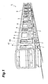
- Fig. 1 shows a perspective view of a rolling stock as an embodiment of a vehicle according to the present invention.
- a side frame 3 of a vehicle body 2 of a rolling stock 1 shown in Fig. 1 rectangular doorways 4 and windows 6 are formed.
- Each doorway 4 is equipped with a double-leaf door 7, which is opened or closed by automatic or manual operation.
- a guide piece 9 is fixed to the lower end of doors 7 by screws.
- the guide piece 9 is inserted into a straight guide groove 8 located on a floor S side, which accomplishes a barrier-free entrance.
- the doorway 4 is provided with a holder unit or a threshold plate 10.
- the threshold plate 10 intends to serve as a barrier-free entrance.
- the threshold plate 10 is fixed outside of the vehicle.
- the threshold plate 10 contributes, for example, to prevention of floor abrasion, reinforcement of a floor and slip prevention when passengers are getting on or off through doorways 4.
- the threshold plate 10 is provided with a step section 11 in flat plate shape.
- the step section 11 is made of, for example, aluminum or stainless steel.
- the step section 11 extends over the substantially whole width of the doorways 4 at the floor S side of the doorways 4.
- a slip stopper 11a which has an uneven shape and extends in the longitudinal direction thereof. That is, at the top face of the step section 11, concavities and convexes extending in the same direction with the width direction of the doorway 4, are formed alternately in a direction intersecting with the width direction.
- This slip stopper 11a ensures the safety on slippery surface on rainy or snowy days.
- screw-insertion holes 11b are formed on the step section 11 of the threshold plate 10.
- the step section 11 is fixed to a doorway frame B via screws 15.
- the doorway frame B defines the doorway 4 at the side of floor S.
- the doorway frame B extends in the vehicle length direction.
- the step section 11 is arranged at the substantially equal level with the floor S. That is, the step section 11 is located along a predetermined standard face, and the top face of the floor S inside the vehicle (floor face), is also located along the predetermined standard face. Specifically, the top face of the doorway frame B performs as a support face for supporting the step section 11, and the support face is positioned below the predetermined standard face. Supporting the step section 11 by this support face reduces the difference in the level between the top face of the step section 11 and the floor face, which accomplishes a barrier-free entrance (Refer to Fig. 3.).
- a light-holder section 12 is integrally formed, protruding downward therefrom. That is, the light-holder section 12 is positioned below the floor face outside the vehicle body.
- the light-holder section 12 provides a space for accommodating a light section 14.
- a light section 14 Formed At a top portion of the light-holder section 12 is an opening 13 in a long shape having substantially equal length with that of the step section 11. Via the opening 13, the light section 14 in a long shape is accommodated in the above-described space. That is, the light section 14 is arranged in such a way that it is positioned outside the vehicle along the lower edge of the doorway 4 extending in the width direction of the doorway 4, and emits light upward.
- a connection cord 16 is extended from one end of the light section 14, and a connector terminal 17 is provided at an end of the connection cord 16. Furthermore, a tongue piece 12a is integrally formed at lower end of the light-holder section 12. The tongue piece 12a contacts with a lower portion of the side frame 3 below the doorway 4. The tongue piece 12a has the substantially same length as that of the light section 14, and achieves the holding of the light-holder section 12 by contacting to the surface of the side frame 3 (Refer to Fig. 3.). The light-holder section 12 projects outside the side frame 3. However, the projection stays within the vehicle gauge.
- An extension section 12b is provided at an end of the light-holder section 12.
- a through hole 18 is formed in the light-holder section 12.
- the through hole 18 connects the space in the extension section 12b with the opening 13 of the light-holder section 12.
- the through hole 18 has a size allowing the connector terminal 17 to pass therethrough.
- the connector terminal 17 of the light section 14 side passes through the space in the extension section 12b along the side frame 3 to outside, and connects to a connector terminal 20 of a cord 19 of the power supply side extended outside from an opening 3a on the side frame 3.
- Connector terminals 17 and 20 positioned outside the cabin are covered with a metallic connector-container case 21, and a lower end of the connector-container case 21 is held by contacting to an upper end of the extension section 12b. Furthermore, the connector-container case 21 is fixed to the side frame 3 of the vehicle body 2 by screws 22, and is detachable from the side frame 3. Therefore, the connector-container case 21 can be removed, when necessary, from the vehicle body 2. Consequently, when the connection between the connector terminal 17 of the light section 14 side and the connector terminal 20 of the vehicle body 2 side is released in a state of removing the connector-container case 21, the light section 14 can be pulled out from the opening 13 of the light-holder section 12. Even if a malfunction of LED (light source) 23 of the light section 14 occurs, the light section 14 is able to be replaced with a new light section 14 easily.
- LED light source
- the step section 11 in flat plate shape provided to the above-described threshold plate 10 functions as a foot-step for passengers to get on or off the vehicle. Since the light section 14 is accommodated in the light-holder section 12 located at the outer end of the step section 11, lighting or flickering of LEDs (light source) 23 in the light section 14 permits the vehicle 1 side to warn the presence of a gap and a difference in level between the edge of the platform and the vehicle body 2, and further clearly indicates the presence of doorways 4 of the vehicle 1 to the physically handicapped persons, aged people, and others.
- the structure is particularly effective in the case where a platform does not give any clear indications of doorway (entrance) 4 positions of a vehicle 1. Therefore, adoption of such type of threshold plate 10 is extremely effective as a facility for smooth getting on or off the vehicle, hence it ensures effectively safety of passengers and the crew.
- the light section 14 has a translucent casing 25 made of resin.
- the casing 25 has a rectangular cross section in a long shape, and is accommodated in the above-described space provided by the light-holder section 12.
- High-luminance white LEDs (light sources) 23 are accommodated in a casing 25, being arranged in a row with an equal spacing therebetween in the door 7 extending direction, or in the width direction of the doorways. The light emitted from each LED 23 passes through a translucent upper wall 25a of the casing 25.
- a water-tight light-source containing space 26 extending in the longitudinal direction at the upper portion of the light section 14 and a screw-containing space 27 extending in the longitudinal direction at the lower portion thereof.
- the light-source containing space 26 and the screw-containing space 27 are separated from each other by a partition 28, thus forming a vertical two-layer structure in the casing 25.
- LEDs 23 are accommodated in the light-source containing space 26.
- LEDs 23 are, for example, white LEDs, the quantity of which is about 50.
- LEDs 23 are fixed in a row on a substrate 29. By inserting the substrate 29 into an insertion groove 30 formed in the casing 25 from a side of the casing 25, LEDs 23 are fixed to the casing 25.
- Several LEDs 23 are connected electrically in series as a group, and each group is connected electrically in parallel with each other, thus it is avoided that all LEDs 23 arranged on the substrate 25 are turned off completely in case of wire-breaking, which secures a safety operation further more.
- a metallic screw seat 31 is accommodated in the screw-containing space 27, and the screw seat 31 is adhered to fix to a bottom wall 25b of the casing 25.
- the screw seat 31 has a female screw section 31a at a predetermined position thereon.
- a screw-insertion hole 32 is formed in the bottom wall 25b of the casing 25 at a position corresponding to the female screw section 31a.
- a Through hole 33 is formed in a bottom wall 12c of the light-holder section 12 at a position corresponding to the screw-insertion hole 32. Accordingly, by screwing a screw 35 which are inserted into the through hole 33 and the screw-insertion hole 32 from beneath thereof to the female screw section 31a of the screw seat 31, the light section 14 can be fixed to the light-holder section 12.
- LEDs 23 Since the light section 14 is detachable from the light-holder section 12, LEDs 23 enables easy access in case of malfunction. Furthermore, adoption of LEDs as the light source 23 allows easy control of the lighting or flickering thereof.
- the casing 25 is divided into the light-source containing space 26 and the screw-containing space 27 by the partition 28, when the light section 14 is fixed to the light-holder section 12 by screws 35, water penetrated through the screw-insertion holes 32 and/or the female screw sections 31a is hindered by the partition 28 from reaching the light-source containing section 26, thus the break of LEDs 23 is prevented.
- a cushion material 36 is filled in between the casing 25 of the light section 14 and the inner wall face of the light-holder section 12 to prevent the light section 14 from chattering. Furthermore, a sealing material 37 is filled in the gap between the casing 25 and the light-holder section 12.
- the lighting control of LEDs 23 is properly changed, when desired. For example, considering safety of passengers, it is preferred that the LEDs 23 are turned on just before opening doors 7, and that the LEDs 23 are turned off immediately after the door 7 is fully closed. In this case, execution of turn-on and turn-off control of LEDs 23 through linked operations of a door switch 40 (refer to Fig. 1) fixed at the upper end of the door 7 and a limit switch 41 (refer to Fig. 1) fixed at the vehicle body 2 side, makes the LED control linked with the open/close operation of the doors 7 easy. Moreover, the LEDs 23 may be flickered during the open/close operation of the doors 7. When passengers manually open the doors 7 on emergency, the LEDs 23 may be turned on.
- Fig. 8 illustrates an example of the light-emission control section which controls emission of light from LEDs.
- the light-emission control section 60 shown in Fig. 8 comprises a switch (the third switch circuit) 62, a power source circuit 64, a switch (the second switch circuit) 66, a switch (the first switch circuit) 68, and a switch 70.
- the doors 7 are to be manually opened.
- driver's action on a release button 82 on the operation panel 80 located in the driver cab enables manual opening operation of doors 7, and by the action of a driver on a close button 84 on the operation panel 80, the automatic closing of the doors 7 is executed.
- One terminal of the switch 62 is connected to a first power source line 72. To the first power source line 72, the power, for example, of 110 V is supplied. Another terminal of the switch 62 is connected to a power source circuit 64. The power source circuit 64 is connected to a second power source line 74, and converts the power received via the switch 62 into a power of a voltage of, for example, 24 V.
- the switch 62 is a switch linked with ON and OFF of room lights. If room lights are ON, the switch 62 turns to ON to supply power from the first power source line 72 to the power source unit 64. Therefore, the light-emission control section 60 is arranged so that current is to be supplied to LEDs 23 only when light emission of LEDs 23 is particularly required such as during nighttime.
- the power source circuit 64 has positive and negative potential lines 76 and 78, respectively.
- the positive potential line 76 is connected to a terminal of the switch 66 and a terminal of the switch 68.
- the switch 66 is a switch linked with open and close of doors 7. In a state where the doors 7 are closed, the switch 66 turns to OFF to cutoff current, while in a state where the doors 7 are opened, the switch 66 turns to ON to allow current to pass therethrough. For example, when the door switch 40 touches the limit switch 41, the switch 66 turns to ON by receiving the signal transmitted from the limit switch 41.
- the switch 68 is a switch linked with a release button 82 and a close button 84 on the operation panel 80 located in a driver cab.
- the switch 68 turns to ON by receiving a release signal transmitted from a door control section 86 to allow current to pass therethrough.
- the close button 84 is pressed down, the switch 68 turns to OFF by receiving a close signal transmitted from the door control section 86 to cutoff current.
- the switch 68 is connected with a switch 70. When doors 7 of the vehicle 1 break down and are locked, the switch 70 turns to OFF.
- a route containing the switch 68 and the switch 70 and a route containing the switch 66 are connected in parallel to a positive electrode of LED 23, while a negative electrode of the LED 23 is connected to a second potential line 78.
- the operation of the light-emission control section 60 having the above-described structure is described below.
- the switch 62 and the switch 70 are assumed to be at ON position.
- doors 7 are closed, and manual operation of doors 7 is disabled, (or in a state that a close signal is supplied). Therefore, both the switch 66 and the switch 68 are in OFF position, and no current is supplied to LEDs 23. Consequently, in that state, LEDs 23 do not emit light.
- a release signal is transmitted to allow the manual opening of doors 7.
- the switch 68 turns to ON to supply current to LEDs 23 via a route containing the switch 68. Then, once the manual opening of the doors 7 becomes available, the light-emission control section 60 makes LEDs 23 ready to emit the light even before opening doors 7 by passengers or other persons, whereby the presence of doorways can be notified on the spot of manual door opening operation of doors 7 start.
- the switch 66 When the doors 7 are manually opened, the switch 66 turns to ON. In that state, when the close button 84 on the operation panel 80 is pressed down, a close signal is output, and the switch 68 turns to OFF with the close signal received to cutoff the current on the route containing the switch 68, thus the automatic closing operation of the door 7 starts. Once the doors 7 are fully closed, the switch 66 receives a signal from the limit switch 41 to turn to OFF, thus cutting off the current supply route to LEDs 23, whereby the light emission of LEDs 23 stops. According to the light-emission control section 60, LEDs 23 continues to emit light until the doors 7 come to closed position completely, which ensures higher degree of safety.
- the threshold plate 10 may be fixed to a conventional threshold plate 44 by screws 45, thus readily applying to existing rolling stocks.
- a guide rail 46 of a door 7 may project from the floor S, and the guide rail 46 may be inserted into a guide groove 47 located at the bottom of the door 7.
- the threshold plate 10 may be fixed by screws at the threshold plate position of the cabin side near the door 7. In that case, the light-holder section 12 is buried in the floor S.
- the resin casing 25 may be transparent or translucent, and the casing 25 may be formed by such a metal as aluminum to increase the strength thereof. If the casing 25 made of resin or metal is opaque, the top wall 25a is formed as a separate component by a transparent or translucent glass or resin. To increase luminance, the inner wall surface of the casing 25 may have a reflection film.
- the above-described threshold plate 10 may be applied to each step of a staircase in a double-decker.
- the present invention ensures further safety of passengers and the crew when getting on or off a vehicle.
- the above-described embodiment according to the present invention refers to rolling stocks. However, it is readily understood for the persons skilled in the art that the present invention is not limited to rolling stocks but is applicable to various vehicles including buses.
Abstract
Description
- The present invention relates to a vehicle.
- Vehicles have various safety measures for passengers and other persons. For example, rolling stocks which have been generally used heretofore are equipped with automatically or manually operating doors at doorways of a vehicle body, allowing to be opened and closed freely, and threshold plates are fixed on the floor side of individual doorways. The threshold plates contribute to prevention of floor abrasion, floor reinforcement and slip prevention when passengers are getting on or off through doorways. (For example, refer to Japanese Patent Laid-Open No. 2000-108898.)
- Each of the threshold plates used in the above-described conventional rolling stocks has an adequate shape for passenger's convenience, and secures safety of passengers by means of slip stoppers or the like when they get on or off the vehicle.
- Incidentally, there is a specified gap and a difference in level between the platform and the vehicle. There is a means on a platform to induce recognition of the presence of a gap and a difference in level to passengers and a measure to clearly suggest the presence of doorways of a vehicle to physically handicapped persons, aged people, and others, but there is no such means on a rolling stock side.
- An object of the present invention is to provide a vehicle which is arranged so that safety of passengers and crew can be secured when getting on or off a vehicle.
- The vehicle according to the present invention comprises: a door for opening and closing a doorway of a vehicle body, and a light section for emitting light, which is provided along the lower edge of the doorway.
- According to the vehicle of the present invention, lighting or flickering by the light section allows the vehicle side to warn the presence of a gap and a difference in level between the edge of platform and the vehicle body, which improves safety of passengers and the crew getting on or off the vehicle.
- Preferably the light section is provided along the lower edge of the doorway outside of the vehicle body, and preferably the light section emits the light upward. According to such structure, the position of the lower edge of the doorway can be clearly indicated.
- Preferably, the vehicle according to the present invention further comprises a holder unit for attaching the light section to the vehicle body. The holder unit includes a step section which is in flat plate shape and is fixed to the vehicle body substantially horizontally, and a light-holder section for providing a space in which the light section is set. The light-holder section is provided on the outer end of the step section and protrudes downward from the step section.
- That is, the holder unit has a step section in substantially horizontally flat plate shape, which functions as a foot-step. Since the light section is set in the light-holder section provided on the outer end of the step section, lighting or flickering of the light section allows a vehicle side to warn the presence of a gap or a difference in level between the edge of platform and the vehicle, and give clear suggestion of the presence of doorway of the vehicle to physically handicapped persons, aged people, and others. In particular, lighting or flickering of the light section is effective when the platform does not give any clear indication of the position of the doorway (entrance). Therefore, adoption of such holder unit is extremely effective as a facility for smooth getting on or off the vehicle, and is extremely effective to secure further safety of passengers and the crew. In addition, according to the structure, the light section is fixed to the vehicle body via the holder unit so that handling of the light section becomes easy.
- In the present invention, it is preferable that a floor face inside the vehicle and the top face of the step section are arranged along a predetermined standard face. With such structure, the difference in level between the step section and the floor face in the vehicle becomes small, thus safety around the doorway can be further improved. Preferably the vehicle according to the present invention further includes a support face for supporting the step section, and the support face is located below the predetermined standard face. Adoption of the support face readily allows matching of the floor face inside the vehicle and the top face of the step section with the above-described predetermined standard face.
- In the vehicle of the present invention, the light-holder section is preferably protruded downward from the floor face outside the vehicle body. With such structure, the light-holder section does not hinder the doorway so that safety of the vehicle is further improved.
- In the vehicle of the present invention, the top face of the step section is preferably provided with a slip stopper section which is an uneven shape. According to such structure, safety on slippery surface on rainy or snowy days is ensured in addition to the safety owing to the lighting or flickering of the light section.
- The vehicle of the present invention preferably further comprises a connector container case for containing a connector terminal of the light section, and the connector container case is preferably detachable from a side frame of the vehicle body. In that case, when the connector container case is detached from the vehicle body, the connection between the connecter terminal extended from the light section and the connector terminal extended from the vehicle body can be released, which allows readily replacing the burnt-out light source during maintenance.
- In the vehicle of the present invention, it is preferable that an opening for setting the light section in a long shape within the space therefrom is provided at an upper portion of the light-holder section, and the light section comprises a plurality of LEDs arranged in a direction of the doorway width, and a casing for accommodating the LEDs, wherein the casing is provided with a partition for separating a water-tight light-source containing space which is formed at an upper part of the casing and accommodates the LEDs, from a screw containing space which is formed at a lower part of the casing and accommodates a screw seat, a bottom wall which has a screw-insertion hole opened at a position corresponding to a position of a female screw formed in the screw seat, and a top wall through which the light emitted from the LEDs transmits.
- According to the structure described above, the light-holder section has the opening so that the mounting and dismounting of the light section is easily executed. Therefore, the structure allows readily replacing a burnt-out light-source. In addition, adoption of LEDs as the light source makes the control of lighting or flickering of light easy. Furthermore, a space in the casing is divided into the light-source containing space and the screw-containing space by the partition. Consequently, when the light section is fixed to the light-holder section using the screw, water penetration through the screw-insertion hole and/or the female screw section is blocked by the partition, thus the water does not reach the light-source containing space, which prevents the LEDs contained in the light-source containing space from breaking.
- The vehicle of the present invention preferably has a light-emission control section which controls supply of current for emitting light from the light section, wherein the light-emission control section comprises: a first switch circuit which supplies current to the light section when receiving a release signal to enable the door to be opened, and stops current supply to the light section when receiving a close signal to close the door; and a second switch circuit which stops current supply to the light section while the door is kept closed and supplies current to the light section while the door is kept opened.
- According to the structure, when the door is enabled to be opened manually, current is supplied to the light section, and while the door are kept closed, current supply to the light section is stopped, whereby unnecessary power consumption is suppressed. When the door is enabled to be opened manually, current is supplied to the light section so that the light section can emit the light before opening the door. The first switch circuit and the second switch circuit are preferably arranged in parallel between an electric potential line and an input terminal of the light section.
- In the vehicle of the present invention, the light-emission control section preferably further comprises a third switch circuit which stops current supply to the light section when a room light of the vehicle is kept turned-off state. According to such structure, current supply to the light section becomes possible only when the room light of the vehicle is turned on, which further suppresses unnecessary power consumption. In addition, it is possible to supply current to the light section only when light emission is required during nighttime, and the like.
-
- Fig. 1 shows a perspective view of a rolling stock of an embodiment of the vehicle according to the present invention.
- Fig. 2 shows a perspective view of a threshold plate applied to the rolling stock.
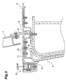
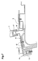
- Fig. 3 shows a cross-sectional view of a doorway to which the threshold plate is fixed.
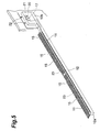
- Fig. 4 shows an exploded perspective view of the threshold plate.
- Fig. 5 shows a perspective view of the threshold plate.
- Fig. 6 shows a cross-sectional view of the threshold plate.
- Fig. 7 shows a cross-sectional view of a threshold plate in another example.
- Fig. 8 shows an example of a light-emission control section for controlling the light emission from LEDs.
-
- The detailed description of a rolling stock as a preferred embodiment of the vehicle according to the present invention will be described below with reference to the drawings.
- Fig. 1 shows a perspective view of a rolling stock as an embodiment of a vehicle according to the present invention. In a
side frame 3 of avehicle body 2 of a rolling stock 1 shown in Fig. 1,rectangular doorways 4 andwindows 6 are formed. Eachdoorway 4 is equipped with a double-leaf door 7, which is opened or closed by automatic or manual operation. - As shown in Fig. 2 and Fig. 3, a
guide piece 9 is fixed to the lower end ofdoors 7 by screws. Theguide piece 9 is inserted into astraight guide groove 8 located on a floor S side, which accomplishes a barrier-free entrance. - The
doorway 4 is provided with a holder unit or athreshold plate 10. Thethreshold plate 10 intends to serve as a barrier-free entrance. Thethreshold plate 10 is fixed outside of the vehicle. Thethreshold plate 10 contributes, for example, to prevention of floor abrasion, reinforcement of a floor and slip prevention when passengers are getting on or off throughdoorways 4. - As shown in Fig. 4 and Fig. 5, the
threshold plate 10 is provided with astep section 11 in flat plate shape. Thestep section 11 is made of, for example, aluminum or stainless steel. Thestep section 11 extends over the substantially whole width of thedoorways 4 at the floor S side of thedoorways 4. - Provided at the top face of the
step section 11 is aslip stopper 11a which has an uneven shape and extends in the longitudinal direction thereof. That is, at the top face of thestep section 11, concavities and convexes extending in the same direction with the width direction of thedoorway 4, are formed alternately in a direction intersecting with the width direction. Thisslip stopper 11a ensures the safety on slippery surface on rainy or snowy days. - Furthermore, screw-
insertion holes 11b are formed on thestep section 11 of thethreshold plate 10. Thestep section 11 is fixed to a doorway frame B via screws 15. The doorway frame B defines thedoorway 4 at the side of floor S. The doorway frame B extends in the vehicle length direction. - The
step section 11 is arranged at the substantially equal level with the floor S. That is, thestep section 11 is located along a predetermined standard face, and the top face of the floor S inside the vehicle (floor face), is also located along the predetermined standard face. Specifically, the top face of the doorway frame B performs as a support face for supporting thestep section 11, and the support face is positioned below the predetermined standard face. Supporting thestep section 11 by this support face reduces the difference in the level between the top face of thestep section 11 and the floor face, which accomplishes a barrier-free entrance (Refer to Fig. 3.). - At an outer end of the
step section 11, a light-holder section 12 is integrally formed, protruding downward therefrom. That is, the light-holder section 12 is positioned below the floor face outside the vehicle body. - The light-
holder section 12 provides a space for accommodating alight section 14. Formed At a top portion of the light-holder section 12 is anopening 13 in a long shape having substantially equal length with that of thestep section 11. Via theopening 13, thelight section 14 in a long shape is accommodated in the above-described space. That is, thelight section 14 is arranged in such a way that it is positioned outside the vehicle along the lower edge of thedoorway 4 extending in the width direction of thedoorway 4, and emits light upward. - A
connection cord 16 is extended from one end of thelight section 14, and aconnector terminal 17 is provided at an end of theconnection cord 16. Furthermore, atongue piece 12a is integrally formed at lower end of the light-holder section 12. Thetongue piece 12a contacts with a lower portion of theside frame 3 below thedoorway 4. Thetongue piece 12a has the substantially same length as that of thelight section 14, and achieves the holding of the light-holder section 12 by contacting to the surface of the side frame 3 (Refer to Fig. 3.). The light-holder section 12 projects outside theside frame 3. However, the projection stays within the vehicle gauge. - An
extension section 12b is provided at an end of the light-holder section 12. A throughhole 18 is formed in the light-holder section 12. The throughhole 18 connects the space in theextension section 12b with theopening 13 of the light-holder section 12. The throughhole 18 has a size allowing theconnector terminal 17 to pass therethrough. Theconnector terminal 17 of thelight section 14 side passes through the space in theextension section 12b along theside frame 3 to outside, and connects to aconnector terminal 20 of acord 19 of the power supply side extended outside from anopening 3a on theside frame 3. -
Connector terminals container case 21, and a lower end of the connector-container case 21 is held by contacting to an upper end of theextension section 12b. Furthermore, the connector-container case 21 is fixed to theside frame 3 of thevehicle body 2 byscrews 22, and is detachable from theside frame 3. Therefore, the connector-container case 21 can be removed, when necessary, from thevehicle body 2. Consequently, when the connection between theconnector terminal 17 of thelight section 14 side and theconnector terminal 20 of thevehicle body 2 side is released in a state of removing the connector-container case 21, thelight section 14 can be pulled out from theopening 13 of the light-holder section 12. Even if a malfunction of LED (light source) 23 of thelight section 14 occurs, thelight section 14 is able to be replaced with anew light section 14 easily. - The
step section 11 in flat plate shape provided to the above-describedthreshold plate 10 functions as a foot-step for passengers to get on or off the vehicle. Since thelight section 14 is accommodated in the light-holder section 12 located at the outer end of thestep section 11, lighting or flickering of LEDs (light source) 23 in thelight section 14 permits the vehicle 1 side to warn the presence of a gap and a difference in level between the edge of the platform and thevehicle body 2, and further clearly indicates the presence ofdoorways 4 of the vehicle 1 to the physically handicapped persons, aged people, and others. The structure is particularly effective in the case where a platform does not give any clear indications of doorway (entrance) 4 positions of a vehicle 1. Therefore, adoption of such type ofthreshold plate 10 is extremely effective as a facility for smooth getting on or off the vehicle, hence it ensures effectively safety of passengers and the crew. - As shown in Fig. 5 and Fig. 6, the
light section 14 has atranslucent casing 25 made of resin. Thecasing 25 has a rectangular cross section in a long shape, and is accommodated in the above-described space provided by the light-holder section 12. High-luminance white LEDs (light sources) 23 are accommodated in acasing 25, being arranged in a row with an equal spacing therebetween in thedoor 7 extending direction, or in the width direction of the doorways. The light emitted from eachLED 23 passes through a translucentupper wall 25a of thecasing 25. - In the
casing 25 of thelight section 14, there are formed a water-tight light-source containing space 26 extending in the longitudinal direction at the upper portion of thelight section 14 and a screw-containingspace 27 extending in the longitudinal direction at the lower portion thereof. The light-source containing space 26 and the screw-containingspace 27 are separated from each other by apartition 28, thus forming a vertical two-layer structure in thecasing 25. - A plurality of
LEDs 23 is accommodated in the light-source containing space 26.LEDs 23 are, for example, white LEDs, the quantity of which is about 50.LEDs 23 are fixed in a row on asubstrate 29. By inserting thesubstrate 29 into aninsertion groove 30 formed in thecasing 25 from a side of thecasing 25,LEDs 23 are fixed to thecasing 25.Several LEDs 23 are connected electrically in series as a group, and each group is connected electrically in parallel with each other, thus it is avoided that allLEDs 23 arranged on thesubstrate 25 are turned off completely in case of wire-breaking, which secures a safety operation further more. - A
metallic screw seat 31 is accommodated in the screw-containingspace 27, and thescrew seat 31 is adhered to fix to abottom wall 25b of thecasing 25. Thescrew seat 31 has afemale screw section 31a at a predetermined position thereon. A screw-insertion hole 32 is formed in thebottom wall 25b of thecasing 25 at a position corresponding to thefemale screw section 31a. AThrough hole 33 is formed in abottom wall 12c of the light-holder section 12 at a position corresponding to the screw-insertion hole 32. Accordingly, by screwing ascrew 35 which are inserted into the throughhole 33 and the screw-insertion hole 32 from beneath thereof to thefemale screw section 31a of thescrew seat 31, thelight section 14 can be fixed to the light-holder section 12. - Since the
light section 14 is detachable from the light-holder section 12,LEDs 23 enables easy access in case of malfunction. Furthermore, adoption of LEDs as thelight source 23 allows easy control of the lighting or flickering thereof. In addition, since thecasing 25 is divided into the light-source containing space 26 and the screw-containingspace 27 by thepartition 28, when thelight section 14 is fixed to the light-holder section 12 byscrews 35, water penetrated through the screw-insertion holes 32 and/or thefemale screw sections 31a is hindered by thepartition 28 from reaching the light-source containing section 26, thus the break ofLEDs 23 is prevented. - On fixing the
light section 14 to the light-holder section 12, acushion material 36 is filled in between the casing 25 of thelight section 14 and the inner wall face of the light-holder section 12 to prevent thelight section 14 from chattering. Furthermore, a sealingmaterial 37 is filled in the gap between thecasing 25 and the light-holder section 12. - The lighting control of
LEDs 23 is properly changed, when desired. For example, considering safety of passengers, it is preferred that theLEDs 23 are turned on just before openingdoors 7, and that theLEDs 23 are turned off immediately after thedoor 7 is fully closed. In this case, execution of turn-on and turn-off control ofLEDs 23 through linked operations of a door switch 40 (refer to Fig. 1) fixed at the upper end of thedoor 7 and a limit switch 41 (refer to Fig. 1) fixed at thevehicle body 2 side, makes the LED control linked with the open/close operation of thedoors 7 easy. Moreover, theLEDs 23 may be flickered during the open/close operation of thedoors 7. When passengers manually open thedoors 7 on emergency, theLEDs 23 may be turned on. - Fig. 8 illustrates an example of the light-emission control section which controls emission of light from LEDs. The light-
emission control section 60 shown in Fig. 8 comprises a switch (the third switch circuit) 62, apower source circuit 64, a switch (the second switch circuit) 66, a switch (the first switch circuit) 68, and aswitch 70. In the vehicle 1 which is provided with the light-emission control section 60 shown in Fig. 8, thedoors 7 are to be manually opened. In this vehicle 1, driver's action on arelease button 82 on theoperation panel 80 located in the driver cab enables manual opening operation ofdoors 7, and by the action of a driver on aclose button 84 on theoperation panel 80, the automatic closing of thedoors 7 is executed. - One terminal of the
switch 62 is connected to a firstpower source line 72. To the firstpower source line 72, the power, for example, of 110 V is supplied. Another terminal of theswitch 62 is connected to apower source circuit 64. Thepower source circuit 64 is connected to a secondpower source line 74, and converts the power received via theswitch 62 into a power of a voltage of, for example, 24 V. - The
switch 62 is a switch linked with ON and OFF of room lights. If room lights are ON, theswitch 62 turns to ON to supply power from the firstpower source line 72 to thepower source unit 64. Therefore, the light-emission control section 60 is arranged so that current is to be supplied toLEDs 23 only when light emission ofLEDs 23 is particularly required such as during nighttime. - The
power source circuit 64 has positive and negativepotential lines potential line 76 is connected to a terminal of theswitch 66 and a terminal of theswitch 68. - The
switch 66 is a switch linked with open and close ofdoors 7. In a state where thedoors 7 are closed, theswitch 66 turns to OFF to cutoff current, while in a state where thedoors 7 are opened, theswitch 66 turns to ON to allow current to pass therethrough. For example, when the door switch 40 touches thelimit switch 41, theswitch 66 turns to ON by receiving the signal transmitted from thelimit switch 41. - The
switch 68 is a switch linked with arelease button 82 and aclose button 84 on theoperation panel 80 located in a driver cab. When therelease button 82 is pressed down, theswitch 68 turns to ON by receiving a release signal transmitted from adoor control section 86 to allow current to pass therethrough. On the other hand, when theclose button 84 is pressed down, theswitch 68 turns to OFF by receiving a close signal transmitted from thedoor control section 86 to cutoff current. - The
switch 68 is connected with aswitch 70. Whendoors 7 of the vehicle 1 break down and are locked, theswitch 70 turns to OFF. - In the light-
emission control section 60, a route containing theswitch 68 and theswitch 70 and a route containing theswitch 66 are connected in parallel to a positive electrode ofLED 23, while a negative electrode of theLED 23 is connected to a secondpotential line 78. - The operation of the light-
emission control section 60 having the above-described structure is described below. Theswitch 62 and theswitch 70 are assumed to be at ON position. During running mode of a vehicle 1,doors 7 are closed, and manual operation ofdoors 7 is disabled, (or in a state that a close signal is supplied). Therefore, both theswitch 66 and theswitch 68 are in OFF position, and no current is supplied toLEDs 23. Consequently, in that state,LEDs 23 do not emit light. - When one of the crew presses down the
release button 82 on theoperation panel 80 in the occasion of stopping at a platform and the like, a release signal is transmitted to allow the manual opening ofdoors 7. On receiving a release signal, theswitch 68 turns to ON to supply current toLEDs 23 via a route containing theswitch 68. Then, once the manual opening of thedoors 7 becomes available, the light-emission control section 60 makesLEDs 23 ready to emit the light even before openingdoors 7 by passengers or other persons, whereby the presence of doorways can be notified on the spot of manual door opening operation ofdoors 7 start. - When the
doors 7 are manually opened, theswitch 66 turns to ON. In that state, when theclose button 84 on theoperation panel 80 is pressed down, a close signal is output, and theswitch 68 turns to OFF with the close signal received to cutoff the current on the route containing theswitch 68, thus the automatic closing operation of thedoor 7 starts. Once thedoors 7 are fully closed, theswitch 66 receives a signal from thelimit switch 41 to turn to OFF, thus cutting off the current supply route toLEDs 23, whereby the light emission ofLEDs 23 stops. According to the light-emission control section 60,LEDs 23 continues to emit light until thedoors 7 come to closed position completely, which ensures higher degree of safety. - A preferred embodiment according to the present invention was described above. However, the present invention is not limited to the above embodiment. For example, as shown in Fig. 7, the
threshold plate 10 may be fixed to aconventional threshold plate 44 byscrews 45, thus readily applying to existing rolling stocks. Aguide rail 46 of adoor 7 may project from the floor S, and theguide rail 46 may be inserted into aguide groove 47 located at the bottom of thedoor 7. Alternatively, thethreshold plate 10 may be fixed by screws at the threshold plate position of the cabin side near thedoor 7. In that case, the light-holder section 12 is buried in the floor S. - Furthermore, the
resin casing 25 may be transparent or translucent, and thecasing 25 may be formed by such a metal as aluminum to increase the strength thereof. If thecasing 25 made of resin or metal is opaque, thetop wall 25a is formed as a separate component by a transparent or translucent glass or resin. To increase luminance, the inner wall surface of thecasing 25 may have a reflection film. The above-describedthreshold plate 10 may be applied to each step of a staircase in a double-decker. - As described above in a preferred embodiment according to the present invention, the present invention ensures further safety of passengers and the crew when getting on or off a vehicle. The above-described embodiment according to the present invention refers to rolling stocks. However, it is readily understood for the persons skilled in the art that the present invention is not limited to rolling stocks but is applicable to various vehicles including buses.
Claims (13)
- A vehicle comprising:a door for opening and closing a doorway of a vehicle body; anda light section for emitting light, the light section being provided along a lower edge of the doorway.
- The vehicle according to claim 1, wherein the light section are provided along the lower edge of the doorway outside the vehicle body.
- The vehicle according to claim 1 or claim 2, wherein the light section emit the light upward.
- The vehicle according to any one of claims 1 to 3, further comprising holder unit for attaching the light section to the vehicle body,
wherein the holder unit comprising:a step section which is in flat plate shape and is fixed to the vehicle body substantially horizontally; anda light-holder section for providing a space in which the light section is set, the light-holder section being provided on an outer end of the step section and being protruded downward from the step section. - The vehicle according to claim 4, wherein the floor face inside the vehicle and the top face of the step section are arranged along a predetermined standard face.
- The vehicle according to claim 5, further comprising a support face for supporting the step section, wherein the support face being located below the predetermined standard face.
- The vehicle according to any one of claims 4 to 6, wherein the light-holder section protrudes downward from the floor face outside the vehicle body.
- The vehicle according to any one of claims 4 to 7, wherein the top face of the step section has a slip stopper section which is an uneven shape.
- The vehicle according to any one of claims 4 to 8, further comprising a connector-container case for containing a connector terminal of the light section, wherein the connector-container case is detachable from a side frame of the vehicle body.
- The vehicle according to any one of claims 4 to 9, wherein an opening for accommodating the light section in a long shape within the space therefrom is provided at an upper portion of the light-holder section,
wherein the light section comprising:wherein the casing comprising:a plurality of LEDs being arranged in a width direction of the doorway; anda casing for accommodating the LEDs,a partition for separating a water-tight light-source containing space which is formed at an upper part of the casing and accommodates the LEDs, from a screw-containing space which is formed at a lower part of the casing and accommodates a screw seat;a bottom wall having an screw-insertion hole opened at a position corresponding to a position of a female screw formed in the screw seat; anda top wall through which the light emitted from the LEDs transmit. - The vehicle according to any one of claims 1 to 10, further comprising a light-emission control section which controls supply of current for emitting light from the light section, wherein the light-emission control section comprising:a first switch circuit which supplies current to the light section when receiving a release signal to enable the door to be opened, and stops current supply to the light section when receiving a close signal to close the door; anda second switch circuit which stops current supply to the light sections when the door is kept closed, and supplies current to the light section when the door is kept opened.
- The vehicle according to claim 11, wherein the first switch circuit and the second switch circuit are arranged in parallel between an electric-potential line and an input terminal of the light section.
- The vehicle according to claim 11 or claim 12, wherein the light-emission control section further comprising a third switch circuit which stops current supply to the light section when a room light of the vehicle is kept turned off.
Applications Claiming Priority (2)
| Application Number | Priority Date | Filing Date | Title |
|---|---|---|---|
| JP2003388367A JP4095951B2 (en) | 2003-11-18 | 2003-11-18 | Railway vehicle |
| JP2003388367 | 2003-11-18 |
Publications (2)
| Publication Number | Publication Date |
|---|---|
| EP1533205A1 true EP1533205A1 (en) | 2005-05-25 |
| EP1533205B1 EP1533205B1 (en) | 2008-07-09 |
Family
ID=34431553
Family Applications (1)
| Application Number | Title | Priority Date | Filing Date |
|---|---|---|---|
| EP04026597A Expired - Fee Related EP1533205B1 (en) | 2003-11-18 | 2004-11-09 | Vehicle with a door step comprising a security lighting. |
Country Status (7)
| Country | Link |
|---|---|
| EP (1) | EP1533205B1 (en) |
| JP (1) | JP4095951B2 (en) |
| KR (1) | KR101087561B1 (en) |
| CN (1) | CN100545004C (en) |
| DE (1) | DE602004014883D1 (en) |
| ES (1) | ES2308088T3 (en) |
| TW (1) | TW200517286A (en) |
Cited By (4)
| Publication number | Priority date | Publication date | Assignee | Title |
|---|---|---|---|---|
| EP2581642A1 (en) * | 2011-10-13 | 2013-04-17 | Scania CV AB (publ) | Stairway configuration for vehicle |
| AT14212U1 (en) * | 2014-03-31 | 2015-06-15 | Knorr Bremse Gmbh Division Ife Automatic Door Systems | Lighting for vehicle doors |
| EP3409557A1 (en) * | 2017-06-01 | 2018-12-05 | JC Disseny Ingenieria i Aplicacions S.L. | Sealing strip for vehicle doors |
| WO2022017682A1 (en) * | 2020-07-22 | 2022-01-27 | Knorr-Bremse Gesellschaft Mit Beschränkter Haftung | Light strip device for a door leaf of a boarding system of a rail vehicle |
Families Citing this family (14)
| Publication number | Priority date | Publication date | Assignee | Title |
|---|---|---|---|---|
| JP4538379B2 (en) * | 2005-06-13 | 2010-09-08 | 東急車輛製造株式会社 | Step light device |
| JP4597786B2 (en) * | 2005-06-13 | 2010-12-15 | 東急車輛製造株式会社 | Vehicle lighting device |
| JP2007099041A (en) * | 2005-10-03 | 2007-04-19 | Tokyo Denso Kk | Guide rail of door of electric car |
| JP2008174183A (en) * | 2007-01-22 | 2008-07-31 | Matsushita Electric Works Ltd | Footstool-integrated luminescence panel |
| JP4913653B2 (en) * | 2007-04-05 | 2012-04-11 | 東急車輛製造株式会社 | Entry / exit indicator |
| KR100827990B1 (en) * | 2007-06-29 | 2008-05-08 | 권의용 | Foot plate structure of gangway connecting rail cars |
| JP5171532B2 (en) * | 2007-10-16 | 2013-03-27 | 川崎重工業株式会社 | Luminous grip bars for railway vehicles |
| KR200446378Y1 (en) * | 2007-12-20 | 2009-10-27 | 김수군 | A sliding door protector of train |
| DE102010004116A1 (en) * | 2010-01-07 | 2011-07-14 | TÜV NORD Sys Tec GmbH & Co. KG, 22525 | Passage for e.g. rail car, has lighting device provided in base in region of doors and producing optical warning signal in response to closing signal, where warning signal indicates closing of door |
| KR101147070B1 (en) * | 2010-10-11 | 2012-05-17 | (주) 첨성시스템 | A Safety Lighting Device of an Entrance |
| JP6976149B2 (en) * | 2017-11-27 | 2021-12-08 | 株式会社総合車両製作所 | Railroad vehicle |
| JP2019094019A (en) * | 2017-11-27 | 2019-06-20 | 株式会社総合車両製作所 | Railway vehicle |
| CN109278778A (en) * | 2018-09-03 | 2019-01-29 | 重庆中车长客轨道车辆有限公司 | A kind of rail vehicle door pedal system and rail vehicle |
| CN115071766B (en) * | 2022-07-27 | 2022-11-08 | 中车长春轨道客车股份有限公司 | Control system and control method of clearance relieving device |
Citations (4)
| Publication number | Priority date | Publication date | Assignee | Title |
|---|---|---|---|---|
| GB2324901A (en) * | 1997-04-29 | 1998-11-04 | Malham Lighting Design Ltd | Lighting arrangement |
| JP2000108898A (en) * | 1998-10-08 | 2000-04-18 | Nippon Sharyo Seizo Kaisha Ltd | Airtight sliding door device |
| JP2000219130A (en) * | 1999-01-28 | 2000-08-08 | Shin Karasawa | Safety display device for platform |
| DE20205304U1 (en) * | 2002-04-05 | 2002-07-25 | Dwa Deutsche Waggonbau Gmbh | Step for entry areas of rail vehicles |
Family Cites Families (2)
| Publication number | Priority date | Publication date | Assignee | Title |
|---|---|---|---|---|
| JPH0131548Y2 (en) | 1985-04-03 | 1989-09-27 | ||
| JP2000255318A (en) | 1999-03-10 | 2000-09-19 | Taisei Seisakusho:Kk | Step clarifying device of automobile |
-
2003
- 2003-11-18 JP JP2003388367A patent/JP4095951B2/en not_active Expired - Fee Related
-
2004
- 2004-11-04 TW TW093133664A patent/TW200517286A/en unknown
- 2004-11-09 DE DE602004014883T patent/DE602004014883D1/en active Active
- 2004-11-09 EP EP04026597A patent/EP1533205B1/en not_active Expired - Fee Related
- 2004-11-09 ES ES04026597T patent/ES2308088T3/en active Active
- 2004-11-17 KR KR1020040093993A patent/KR101087561B1/en active IP Right Grant
- 2004-11-18 CN CNB2004100974397A patent/CN100545004C/en not_active Expired - Fee Related
Patent Citations (4)
| Publication number | Priority date | Publication date | Assignee | Title |
|---|---|---|---|---|
| GB2324901A (en) * | 1997-04-29 | 1998-11-04 | Malham Lighting Design Ltd | Lighting arrangement |
| JP2000108898A (en) * | 1998-10-08 | 2000-04-18 | Nippon Sharyo Seizo Kaisha Ltd | Airtight sliding door device |
| JP2000219130A (en) * | 1999-01-28 | 2000-08-08 | Shin Karasawa | Safety display device for platform |
| DE20205304U1 (en) * | 2002-04-05 | 2002-07-25 | Dwa Deutsche Waggonbau Gmbh | Step for entry areas of rail vehicles |
Non-Patent Citations (2)
| Title |
|---|
| PATENT ABSTRACTS OF JAPAN vol. 2000, no. 07 29 September 2000 (2000-09-29) * |
| PATENT ABSTRACTS OF JAPAN vol. 2000, no. 11 3 January 2001 (2001-01-03) * |
Cited By (6)
| Publication number | Priority date | Publication date | Assignee | Title |
|---|---|---|---|---|
| EP2581642A1 (en) * | 2011-10-13 | 2013-04-17 | Scania CV AB (publ) | Stairway configuration for vehicle |
| AT14212U1 (en) * | 2014-03-31 | 2015-06-15 | Knorr Bremse Gmbh Division Ife Automatic Door Systems | Lighting for vehicle doors |
| WO2015149095A1 (en) | 2014-03-31 | 2015-10-08 | Knorr Bremse Gmbh, Division Ife Automatic Door Systems | Illumination of vehicle doors |
| US10029710B2 (en) | 2014-03-31 | 2018-07-24 | Knorr-Bremse Gmbh | Illumination of vehicle doors |
| EP3409557A1 (en) * | 2017-06-01 | 2018-12-05 | JC Disseny Ingenieria i Aplicacions S.L. | Sealing strip for vehicle doors |
| WO2022017682A1 (en) * | 2020-07-22 | 2022-01-27 | Knorr-Bremse Gesellschaft Mit Beschränkter Haftung | Light strip device for a door leaf of a boarding system of a rail vehicle |
Also Published As
| Publication number | Publication date |
|---|---|
| DE602004014883D1 (en) | 2008-08-21 |
| EP1533205B1 (en) | 2008-07-09 |
| CN100545004C (en) | 2009-09-30 |
| ES2308088T3 (en) | 2008-12-01 |
| KR101087561B1 (en) | 2011-11-28 |
| KR20050048504A (en) | 2005-05-24 |
| JP2005145343A (en) | 2005-06-09 |
| TW200517286A (en) | 2005-06-01 |
| CN1618657A (en) | 2005-05-25 |
| JP4095951B2 (en) | 2008-06-04 |
Similar Documents
| Publication | Publication Date | Title |
|---|---|---|
| EP1533205B1 (en) | Vehicle with a door step comprising a security lighting. | |
| US8475024B2 (en) | Emergency lighting | |
| EP2626850B1 (en) | Sign | |
| CN111051135A (en) | Lighting module | |
| KR101774386B1 (en) | Emergency lighting system for train | |
| US20030006102A1 (en) | Emergency lighting in elevator cars with phosphorescent materials | |
| JP4538379B2 (en) | Step light device | |
| JP2005145344A (en) | Step light | |
| JPH0635800Y2 (en) | Knob for opening the vehicle door | |
| JP4288262B2 (en) | Railroad vehicle floor structure | |
| JP4507853B2 (en) | Elevator equipment | |
| JP4597786B2 (en) | Vehicle lighting device | |
| US5254907A (en) | Lighting system for use in vehicle cabin | |
| KR200493821Y1 (en) | posting device for taxi driver's certification | |
| JP2000255953A (en) | Elevator | |
| KR20210000661U (en) | taxi security light device | |
| JP4847065B2 (en) | Railway vehicle lighting system | |
| JPH066147Y2 (en) | Elevator entrance / exit lighting device | |
| KR100867152B1 (en) | safety lighting Device of PSD base. | |
| JPH11115629A (en) | Vehicular floor | |
| US20230211724A1 (en) | Motor vehicle panel, in particular motor vehicle door | |
| KR20190019480A (en) | Warning apparatus for city bus transport | |
| KR20070101992A (en) | Break open circuit for an elevator | |
| KR20110001737U (en) | A button for alarm getting off the bus | |
| KR100439913B1 (en) | An automobile door courtesy lamp and a device of controlling the same |
Legal Events
| Date | Code | Title | Description |
|---|---|---|---|
| PUAI | Public reference made under article 153(3) epc to a published international application that has entered the european phase |
Free format text: ORIGINAL CODE: 0009012 |
|
| AK | Designated contracting states |
Kind code of ref document: A1 Designated state(s): AT BE BG CH CY CZ DE DK EE ES FI FR GB GR HU IE IS IT LI LU MC NL PL PT RO SE SI SK TR |
|
| AX | Request for extension of the european patent |
Extension state: AL HR LT LV MK YU |
|
| 17P | Request for examination filed |
Effective date: 20051125 |
|
| AKX | Designation fees paid |
Designated state(s): DE ES FR GB IE |
|
| 17Q | First examination report despatched |
Effective date: 20060724 |
|
| GRAP | Despatch of communication of intention to grant a patent |
Free format text: ORIGINAL CODE: EPIDOSNIGR1 |
|
| GRAS | Grant fee paid |
Free format text: ORIGINAL CODE: EPIDOSNIGR3 |
|
| GRAA | (expected) grant |
Free format text: ORIGINAL CODE: 0009210 |
|
| AK | Designated contracting states |
Kind code of ref document: B1 Designated state(s): DE ES FR GB IE |
|
| REG | Reference to a national code |
Ref country code: GB Ref legal event code: FG4D |
|
| REF | Corresponds to: |
Ref document number: 602004014883 Country of ref document: DE Date of ref document: 20080821 Kind code of ref document: P |
|
| REG | Reference to a national code |
Ref country code: IE Ref legal event code: FG4D |
|
| REG | Reference to a national code |
Ref country code: ES Ref legal event code: FG2A Ref document number: 2308088 Country of ref document: ES Kind code of ref document: T3 |
|
| PLBE | No opposition filed within time limit |
Free format text: ORIGINAL CODE: 0009261 |
|
| STAA | Information on the status of an ep patent application or granted ep patent |
Free format text: STATUS: NO OPPOSITION FILED WITHIN TIME LIMIT |
|
| 26N | No opposition filed |
Effective date: 20090414 |
|
| REG | Reference to a national code |
Ref country code: DE Ref legal event code: R082 Ref document number: 602004014883 Country of ref document: DE Representative=s name: GRUENECKER, KINKELDEY, STOCKMAIR & SCHWANHAEUS, DE |
|
| REG | Reference to a national code |
Ref country code: DE Ref legal event code: R081 Ref document number: 602004014883 Country of ref document: DE Owner name: JAPAN TRANSPORT ENGINEERING COMPANY, JP Free format text: FORMER OWNER: TOKYU CAR CORP., YOKOHAMA, JP Effective date: 20121113 Ref country code: DE Ref legal event code: R082 Ref document number: 602004014883 Country of ref document: DE Representative=s name: GRUENECKER, KINKELDEY, STOCKMAIR & SCHWANHAEUS, DE Effective date: 20121113 Ref country code: DE Ref legal event code: R081 Ref document number: 602004014883 Country of ref document: DE Owner name: JAPAN TRANSPORT ENGINEERING COMPANY, YOKOHAMA-, JP Free format text: FORMER OWNER: TOKYU CAR CORP., YOKOHAMA, KANAGAWA, JP Effective date: 20121113 Ref country code: DE Ref legal event code: R082 Ref document number: 602004014883 Country of ref document: DE Representative=s name: GRUENECKER PATENT- UND RECHTSANWAELTE PARTG MB, DE Effective date: 20121113 |
|
| REG | Reference to a national code |
Ref country code: FR Ref legal event code: TP Owner name: JAPAN TRASPORT ENGINEERING COMPANY, JP Effective date: 20121213 |
|
| REG | Reference to a national code |
Ref country code: ES Ref legal event code: PC2A Owner name: JAPAN TRANSPORT ENGINEERING COMPANY Effective date: 20130111 |
|
| REG | Reference to a national code |
Ref country code: GB Ref legal event code: 732E Free format text: REGISTERED BETWEEN 20130117 AND 20130123 |
|
| REG | Reference to a national code |
Ref country code: FR Ref legal event code: PLFP Year of fee payment: 12 |
|
| REG | Reference to a national code |
Ref country code: FR Ref legal event code: PLFP Year of fee payment: 13 |
|
| REG | Reference to a national code |
Ref country code: FR Ref legal event code: PLFP Year of fee payment: 14 |
|
| PGFP | Annual fee paid to national office [announced via postgrant information from national office to epo] |
Ref country code: DE Payment date: 20181126 Year of fee payment: 15 |
|
| PGFP | Annual fee paid to national office [announced via postgrant information from national office to epo] |
Ref country code: ES Payment date: 20181214 Year of fee payment: 15 |
|
| REG | Reference to a national code |
Ref country code: DE Ref legal event code: R119 Ref document number: 602004014883 Country of ref document: DE |
|
| PG25 | Lapsed in a contracting state [announced via postgrant information from national office to epo] |
Ref country code: FR Free format text: LAPSE BECAUSE OF NON-PAYMENT OF DUE FEES Effective date: 20191130 Ref country code: DE Free format text: LAPSE BECAUSE OF NON-PAYMENT OF DUE FEES Effective date: 20200603 |
|
| PGFP | Annual fee paid to national office [announced via postgrant information from national office to epo] |
Ref country code: IE Payment date: 20201119 Year of fee payment: 17 Ref country code: GB Payment date: 20201126 Year of fee payment: 17 |
|
| PG25 | Lapsed in a contracting state [announced via postgrant information from national office to epo] |
Ref country code: ES Free format text: LAPSE BECAUSE OF NON-PAYMENT OF DUE FEES Effective date: 20191110 |
|
| GBPC | Gb: european patent ceased through non-payment of renewal fee |
Effective date: 20211109 |
|
| PG25 | Lapsed in a contracting state [announced via postgrant information from national office to epo] |
Ref country code: IE Free format text: LAPSE BECAUSE OF NON-PAYMENT OF DUE FEES Effective date: 20211109 Ref country code: GB Free format text: LAPSE BECAUSE OF NON-PAYMENT OF DUE FEES Effective date: 20211109 |