EP1533194B1 - Enveloppe gonflable disposée intérieurement au siège pour estimation du poids de l'occupant - Google Patents
Enveloppe gonflable disposée intérieurement au siège pour estimation du poids de l'occupant Download PDFInfo
- Publication number
- EP1533194B1 EP1533194B1 EP04078153A EP04078153A EP1533194B1 EP 1533194 B1 EP1533194 B1 EP 1533194B1 EP 04078153 A EP04078153 A EP 04078153A EP 04078153 A EP04078153 A EP 04078153A EP 1533194 B1 EP1533194 B1 EP 1533194B1
- Authority
- EP
- European Patent Office
- Prior art keywords
- bladder
- elastomeric
- tethers
- occupant weight
- seat
- Prior art date
- Legal status (The legal status is an assumption and is not a legal conclusion. Google has not performed a legal analysis and makes no representation as to the accuracy of the status listed.)
- Expired - Lifetime
Links
- 239000012530 fluid Substances 0.000 claims abstract description 19
- 239000013536 elastomeric material Substances 0.000 claims abstract description 8
- 230000002093 peripheral effect Effects 0.000 claims abstract description 5
- 230000008878 coupling Effects 0.000 claims abstract description 3
- 238000010168 coupling process Methods 0.000 claims abstract description 3
- 238000005859 coupling reaction Methods 0.000 claims abstract description 3
- 239000000463 material Substances 0.000 claims description 3
- 238000000926 separation method Methods 0.000 claims description 3
- 206010000060 Abdominal distension Diseases 0.000 abstract description 4
- 238000011176 pooling Methods 0.000 abstract description 4
- 238000003466 welding Methods 0.000 description 6
- RYECOJGRJDOGPP-UHFFFAOYSA-N Ethylurea Chemical compound CCNC(N)=O RYECOJGRJDOGPP-UHFFFAOYSA-N 0.000 description 2
- 239000006260 foam Substances 0.000 description 2
- 229920002635 polyurethane Polymers 0.000 description 2
- 239000004814 polyurethane Substances 0.000 description 2
- 230000035945 sensitivity Effects 0.000 description 2
- 239000000853 adhesive Substances 0.000 description 1
- 230000001070 adhesive effect Effects 0.000 description 1
- 238000010586 diagram Methods 0.000 description 1
- 238000005516 engineering process Methods 0.000 description 1
- 239000004744 fabric Substances 0.000 description 1
- 238000005304 joining Methods 0.000 description 1
- 238000004519 manufacturing process Methods 0.000 description 1
- 238000000034 method Methods 0.000 description 1
- 238000012986 modification Methods 0.000 description 1
- 230000004048 modification Effects 0.000 description 1
- 229920001296 polysiloxane Polymers 0.000 description 1
- 230000001105 regulatory effect Effects 0.000 description 1
- 238000009958 sewing Methods 0.000 description 1
Images


Classifications
-
- B—PERFORMING OPERATIONS; TRANSPORTING
- B60—VEHICLES IN GENERAL
- B60R—VEHICLES, VEHICLE FITTINGS, OR VEHICLE PARTS, NOT OTHERWISE PROVIDED FOR
- B60R21/00—Arrangements or fittings on vehicles for protecting or preventing injuries to occupants or pedestrians in case of accidents or other traffic risks
- B60R21/01—Electrical circuits for triggering passive safety arrangements, e.g. airbags, safety belt tighteners, in case of vehicle accidents or impending vehicle accidents
- B60R21/015—Electrical circuits for triggering passive safety arrangements, e.g. airbags, safety belt tighteners, in case of vehicle accidents or impending vehicle accidents including means for detecting the presence or position of passengers, passenger seats or child seats, and the related safety parameters therefor, e.g. speed or timing of airbag inflation in relation to occupant position or seat belt use
- B60R21/01512—Passenger detection systems
- B60R21/01516—Passenger detection systems using force or pressure sensing means
Definitions
- the present invention is directed to a fluid-filled seat bladder for vehicle occupant weight estimation, and more particularly to a seat bladder having internal tethering.
- Occupant weight estimation systems are useful in connection with air bags and other pyrotechnically deployed restraints for purposes of discriminating the occupant category and judging whether, and how forcefully, to deploy the restraints.
- a well known weight estimation technique is to locate one or more fluid-filled bladders in or under a vehicle seat cushion, and to estimate the weight of the occupant based on a measure of the pressure in the bladder(s). See for example, the U.S. Patent Nos. 5,987,370 and 6,246,936 to Murphy et al., and the U.S. Patent Nos. 6,101,436 and 6,490,936 to Fortune et al., all of which are assigned to Delphi Technologies, Inc., as well as the U.S. Patent No. 5,957,491 to Cech et al. and the U.S. Patent No. 5,975,568 to Speckhart et al.
- seat bladders are formed by peripherally joining two sheets of elastomeric material, by radio frequency welding, for example. Additional welds may also be formed at various locations within the periphery of the bladder in order to reduce fluid pooling and distention or bulging of the bladder due to localized loading, as well as to reduce the fluid volume, and therefore its weight. These inter-peripheral welds may be spot welds or seam welds, and can be used to form flow-through cells or fluid-free regions. See particularly the aforementioned U.S. Patent Nos. 5,957,491; 5,975,568; 5,987,370; and 6,101,436.
- a drawback of inter-peripheral welding in weight estimation seat bladders is that the bladder material in the vicinity of the weld provides a vertical support that effectively shunts a portion of the occupant weight through the bladder without significantly influencing the fluid pressure within the bladder. As a result, a given weight distributed over a relatively large area of the seat will produce a different pressure reading that the same weight when distributed over a relatively small area of the seat. Accordingly, what is needed is a bladder structure that will achieve the benefits of inter-peripheral welding without providing significant vertical support of occupant weight.
- WO-A-99/11483 showing the features of the preamble of claim 1, discloses a seat weight sensor having a self regulating fluid filled bladder.
- an elastomeric bladder disposed in a vehicle seat according to claim 1.
- the present invention is directed to an improved occupant weight estimation apparatus for a vehicle seat in which an elastomeric seat bladder defined by peripherally welded upper and lower sheets of elastomeric material includes coupling the upper and lower sheets within the peripheral weld in order to reduce fluid pooling and distention or bulging of the bladder due to localized loading.
- the elastomeric tethers are spot or seam welded to upper and lower sheets of the bladder; they extend to limit distension where required, and otherwise partially or fully collapse to minimize vertical shunting of occupant weight through the bladder.
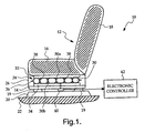
- the reference numeral 10 generally designates a vehicle occupant weight estimation apparatus according to this invention.
- the vehicle seat generally designated by the reference numeral 12, includes a frame 14, a bottom foam cushion 16 and a back foam cushion 18.
- a set of posts 19 integral to the frame 14 attach the seat 12 to a pair of tracks 20 (only one of which is shown in Figure 1), which in turn, are secured to the vehicle floor 22.
- a bladder assembly 24 is sandwiched between the bottom cushion 16 and the frame 14 for the purpose of detecting the presence and weight of an occupant of seat 12.
- a fabric cover 26 envelopes the cushion 16, bladder assembly 24 and frame 14.
- the bladder assembly 24 includes an elastomeric bladder 30 defined by upper and lower sheets 30a, 30b of elastomeric material such as polyurethane or pellethane that are peripherally seam welded as indicated by the reference numeral 36 to form a closed volume that is filled with silicone or another suitable fluid, and a pressure sensor 40 for measuring the fluid pressure in bladder 30.
- elastomeric bladder 30 defined by upper and lower sheets 30a, 30b of elastomeric material such as polyurethane or pellethane that are peripherally seam welded as indicated by the reference numeral 36 to form a closed volume that is filled with silicone or another suitable fluid
- a pressure sensor 40 for measuring the fluid pressure in bladder 30.
- the weight of a vehicle occupant seated on the cushion 16 is applied to the bladder 30, and an electronic controller 42 coupled to the pressure sensor 40 develops an estimation of the occupant weight based on the measured pressure and its variation with respect to time; see, for example, the aforementioned U.S. Patent Nos. 5,987,370 and 6,246,936
- the assembly 24 typically also includes an upper interface panel 32 disposed between the upper bladder sheet 30a and the seat cushion 16, and a lower interface panel 34 disposed between the lower bladder sheet 30b and the seat frame 14.
- the interface panels 32 and 34 protect bladder 30 from puncture damage, and limit the system sensitivity to variations caused by manufacturing irregularities.
- the upper and lower bladder sheets 30a, 30b are joined by spot or seam welding within the peripheral weld 36 to form a plurality of flow-through cells as disclosed in the aforementioned U.S Patent Nos. 5,957,491; 5,975,568; 5,987,370; and 6,101,436.
- the cells advantageously serve to reduce the fluid volume (and therefore weight) and to reduce fluid pooling and distention or bulging of the bladder due to localized loading.
- the cells can be sized and positioned to tailor the bladder sensitivity to the occupant weight, as described for example in the aforementioned U.S. Patent No. 6,101,436.
- the bladder material in the vicinity of the inter-peripheral welds tends to shunt a portion of the occupant weight through the bladder without significantly influencing the fluid pressure within the bladder.
- a given weight distributed over a relatively large area of cushion 16 will produce a different pressure reading than the same weight when distributed over a relatively small area of cushion 16.
- the upper and lower layers 30a, 30b of the bladder 30 are internally coupled within the peripheral weld 36 by a number of elastomeric tethers 38 defined by bands or sheets of elastomeric material such as polyurethane or pellethane that are selectively welded to the upper and lower layers 30a, 30b.
- spot welds attaching the tethers 38 to the upper layer 30a are designated by the reference numeral 44
- spot welds attaching the tethers 38 to the lower layer 30b are designated by the reference numeral 46.
- the tethers 38 effectively create an array of flow-through cells within the bladder 30 as shown in Figures 1 and 2A-2C to achieve the advantages of conventional inter-peripheral spot welding of the layers 30a, 30b, but without establishing a vertical support structure through which occupant weight can be shunted through the bladder 30. Since occupant weight shunting is minimized, the bladder fluid pressure due to occupant seat weight is less sensitive to the area over which the weight is applied, leading to more accurate and consistent weight estimation. Of course, the length and spacing of the tethers 38 can be varied to control the degree of permitted separation of the layers 30a, 30b.
- the tethers 38 restrict separation of the layers 30a, 30b when occupant weight applied to one portion of bladder 30 tends to pool the bladder fluid in other portions of the bladder.
- the tethers 38 normally are in a state of partial collapse, and offer little or no vertical support structure through which occupant weight can be shunted through the bladder 30.
- the tethers 38 fully collapse when the bladder 30 is flattened by an applied load; in this case, nearly all of the bladder fluid is displaced to other portions of the bladder 30 and the layers 30a, 30b are essentially pressed into engagement. In the region of the tethers 38, there will be a slight bulge in the bladder 30, but the bulges are very small and will not affect occupant comfort.
- Figures 3A, 3B and 3C illustrate three different possible arrangements or repeat patterns of tethers 38.
- the upper triangular end 38a signifies a spot weld to the upper layer 30a of bladder 30, and the lower triangular end 38b signifies a spot weld to the lower layer 30b of bladder 30.
- Figure 3A depicts a triangular or diamond-shaped repeat pattern
- Figure 3B depicts a rectangular repeat pattern
- Figure 3A depicts a hexagonal repeat pattern.
- the repeat pattern of tethers 38 defines the cell shape; and in general, a spherical cell shape is preferred as the lowest energy configuration.
- the present invention provides a seat bladder for occupant weight estimation that provides more accurate and consistent weight estimation without sacrificing the advantages achieved by inter-peripheral spot welding. While described in reference to the illustrated embodiments, it should be understood that various modifications will occur to persons skilled in the art.
- the number and shape of the tethers 38 may be different than shown, the two or more individual tethers 38 may be joined into one or more sheets that are perforated for fluid flow, the tethers 38 may be joined to the upper and lower layers 30a, 30b of bladder 30 by sewing or adhesives, and so on.
- any of a number of configurations may fall within the scope of this invention, which is defined by the appended claims.
Landscapes
- Engineering & Computer Science (AREA)
- Mechanical Engineering (AREA)
- Seats For Vehicles (AREA)
- Measuring Pulse, Heart Rate, Blood Pressure Or Blood Flow (AREA)
- Orthopedics, Nursing, And Contraception (AREA)
- Footwear And Its Accessory, Manufacturing Method And Apparatuses (AREA)
- Air Bags (AREA)
Claims (5)
- Enveloppe élastomère (30) disposée dans un siège (12) de véhicule pour une estimation du poids d'un occupant, l'enveloppe (30) comprenant :des feuilles inférieure et supérieure (30a, 30b) de matériau élastomère soudées de manière périphérique (36) pour former un volume fermé contenant un fluide d'enveloppe; etune pluralité d'ancrages élastomères (38) couplant lesdites feuilles supérieure et inférieure (30a, 30b) de matériau élastomère dans ladite soudure périphérique (36), lesdits ancrages (38) étant dans un état d'affaissement partiel quand aucun poids d'occupant n'est appliqué audit siège (12), lesdits ancrages (38) dans l'une quelconque partie donnée de ladite enveloppe (30) s'affaissent davantage quand un poids d'occupant est appliqué au siège ; caractérisée en ce que lesdits ancrages (38) s'étendent pour restreindre une séparation desdites feuilles inférieure et supérieure (30a, 30b) quand un poids d'occupant est appliqué audit siège (12) amenant un fluide d'enveloppe à s'accumuler dans ladite partie de ladite enveloppe (30).
- Enveloppe élastomère selon la revendication 1, dans laquelle au moins un desdits ancrages élastomères (38) est sous la forme d'une bande de matériau élastomère, avec une première extrémité (38a) de ladite bande fixée à ladite feuille supérieure (30a) et une deuxième extrémité (38b) de ladite bande fixée à ladite feuille inférieure (30b).
- Enveloppe élastomère selon l'une des revendications 1 ou 2, dans laquelle lesdits ancrages (38) sont agencés dans un motif géométrique uniforme.
- Enveloppe élastomère selon l'une des revendications 1 ou 2, dans laquelle lesdits ancrages (38) sont agencés dans un motif non uniforme.
- Enveloppe élastomère selon l'une quelconque des revendications précédentes, dans laquelle deux ou plus desdits ancrages (38) sont définis par une feuille de matériau d'ancrage élastomère qui est soudée par points de manière sélective auxdites feuilles inférieure et supérieure (30a, 30b).
Applications Claiming Priority (2)
| Application Number | Priority Date | Filing Date | Title |
|---|---|---|---|
| US718331 | 2003-11-20 | ||
| US10/718,331 US7000948B2 (en) | 2003-11-20 | 2003-11-20 | Internally tethered seat bladder for occupant weight estimation |
Publications (3)
| Publication Number | Publication Date |
|---|---|
| EP1533194A2 EP1533194A2 (fr) | 2005-05-25 |
| EP1533194A3 EP1533194A3 (fr) | 2005-08-17 |
| EP1533194B1 true EP1533194B1 (fr) | 2007-05-30 |
Family
ID=34435778
Family Applications (1)
| Application Number | Title | Priority Date | Filing Date |
|---|---|---|---|
| EP04078153A Expired - Lifetime EP1533194B1 (fr) | 2003-11-20 | 2004-11-18 | Enveloppe gonflable disposée intérieurement au siège pour estimation du poids de l'occupant |
Country Status (4)
| Country | Link |
|---|---|
| US (1) | US7000948B2 (fr) |
| EP (1) | EP1533194B1 (fr) |
| AT (1) | ATE363418T1 (fr) |
| DE (1) | DE602004006696T2 (fr) |
Cited By (2)
| Publication number | Priority date | Publication date | Assignee | Title |
|---|---|---|---|---|
| US8151654B2 (en) | 1998-04-01 | 2012-04-10 | Methode Electronics, Inc. | Sensor pad for controlling airbag deployment and associated support |
| DE102014214926A1 (de) | 2014-07-30 | 2016-02-04 | Bayerische Motoren Werke Aktiengesellschaft | Kraftfahrzeug mit einer Vorrichtung zur Überprüfung der Zuladung und Verfahren zum Überprüfen der Zuladung |
Families Citing this family (8)
| Publication number | Priority date | Publication date | Assignee | Title |
|---|---|---|---|---|
| ATE338660T1 (de) * | 2003-04-23 | 2006-09-15 | Delphi Tech Inc | Insassenerkennungssystem für fahrzeuge |
| JP4622691B2 (ja) * | 2005-06-14 | 2011-02-02 | タカタ株式会社 | エアバッグ、その製造方法、エアバッグ装置及び車両 |
| US20080136227A1 (en) * | 2006-12-11 | 2008-06-12 | 3M Innovative Properties Company | Vehicle seat sensor assembly |
| EP2329769B1 (fr) * | 2008-08-19 | 2015-03-25 | Delta Tooling Co., Ltd. | Dispositif de mesure de signal biométrique et système d'analyse de l'état de l'organisme |
| US8641142B2 (en) * | 2010-11-03 | 2014-02-04 | Delphi Technologies, Inc. | Weight based vehicle seat occupant detection device |
| US11766961B2 (en) * | 2019-11-13 | 2023-09-26 | Langfang Golden Time Technology Development Co., Ltd. | Device for adjusting softness of seat, device for adjusting comfort of seat, and vehicle seat |
| US20240198880A1 (en) * | 2022-12-20 | 2024-06-20 | Lear Corporation | Alternative width massage |
| US12083980B2 (en) * | 2022-06-28 | 2024-09-10 | GM Global Technology Operations LLC | Intelligent seat cushion |
Family Cites Families (12)
| Publication number | Priority date | Publication date | Assignee | Title |
|---|---|---|---|---|
| WO1994023647A1 (fr) * | 1993-04-22 | 1994-10-27 | Pixsys, Inc. | Systeme de determination de la position relative d'objets |
| ES2107104T3 (es) * | 1993-12-18 | 1997-11-16 | Porsche Ag | Dispositivo de proteccion de colision para los ocupantes de un vehiculo automovil. |
| US5957491A (en) * | 1996-12-19 | 1999-09-28 | Automotive Systems Laboratory, Inc. | Seat weight sensor having fluid filled bladder |
| US5987370A (en) * | 1997-09-03 | 1999-11-16 | Delco Electronics Corp. | Vehicle occupant weight estimation apparatus having fluid-filled seat bladder |
| JP2001506009A (ja) | 1997-09-05 | 2001-05-08 | オートモーティブ システムズ ラボラトリー インコーポレーテッド | 自己調整流体を充填したブラダを有する座席重量センサ |
| US5984349A (en) * | 1997-11-17 | 1999-11-16 | Automotive Systems Laboratory, Inc. | Low profile hydraulic seat weight sensor |
| US5975568A (en) | 1998-04-01 | 1999-11-02 | American Components, Inc. | Sensor pad for controlling airbag deployment and associated support |
| US5902010A (en) * | 1998-06-22 | 1999-05-11 | Trw Inc. | Vehicle occupant restraint apparatus |
| US6113141A (en) * | 1998-07-06 | 2000-09-05 | American Components, Inc. | Roll-over air bag |
| US6220629B1 (en) * | 1999-04-21 | 2001-04-24 | Breed Automotive Technology, Inc. | Cushion with increased seam strength and method of assembly |
| US6398253B1 (en) * | 1999-09-01 | 2002-06-04 | Trw Occupant Restraint Systems Gmbh & Co. Kg | Gas bag protective device |
| US6246936B1 (en) | 1999-10-05 | 2001-06-12 | Delphi Technologies, Inc. | Vehicle occupant characterization method based on sensed occupant weight |
-
2003
- 2003-11-20 US US10/718,331 patent/US7000948B2/en not_active Expired - Lifetime
-
2004
- 2004-11-18 DE DE602004006696T patent/DE602004006696T2/de not_active Expired - Lifetime
- 2004-11-18 AT AT04078153T patent/ATE363418T1/de not_active IP Right Cessation
- 2004-11-18 EP EP04078153A patent/EP1533194B1/fr not_active Expired - Lifetime
Cited By (2)
| Publication number | Priority date | Publication date | Assignee | Title |
|---|---|---|---|---|
| US8151654B2 (en) | 1998-04-01 | 2012-04-10 | Methode Electronics, Inc. | Sensor pad for controlling airbag deployment and associated support |
| DE102014214926A1 (de) | 2014-07-30 | 2016-02-04 | Bayerische Motoren Werke Aktiengesellschaft | Kraftfahrzeug mit einer Vorrichtung zur Überprüfung der Zuladung und Verfahren zum Überprüfen der Zuladung |
Also Published As
| Publication number | Publication date |
|---|---|
| US7000948B2 (en) | 2006-02-21 |
| DE602004006696T2 (de) | 2008-01-24 |
| EP1533194A3 (fr) | 2005-08-17 |
| US20050110255A1 (en) | 2005-05-26 |
| DE602004006696D1 (de) | 2007-07-12 |
| EP1533194A2 (fr) | 2005-05-25 |
| ATE363418T1 (de) | 2007-06-15 |
Similar Documents
| Publication | Publication Date | Title |
|---|---|---|
| US5975568A (en) | Sensor pad for controlling airbag deployment and associated support | |
| EP1533194B1 (fr) | Enveloppe gonflable disposée intérieurement au siège pour estimation du poids de l'occupant | |
| US6612609B1 (en) | Inflatable air bag with inner bag and outer bag | |
| US20120166046A1 (en) | Sensor pad for controlling airbag deployment and associated support | |
| US20030020266A1 (en) | Variable venting air bag assembly | |
| US6883831B2 (en) | Apparatus and method for controlling an inflatable cushion | |
| US6101436A (en) | Vehicle occupant weight estimation apparatus having fluid-filled multi-cell seat bladder | |
| JP3626529B2 (ja) | エアバッグ装置の製造方法 | |
| US20030067149A1 (en) | Vehicle occupant weight detection system with occupant position compensation | |
| EP1459942A1 (fr) | Dispositif de protection de passager | |
| US6918612B2 (en) | Electronic seat occupant classification system | |
| EP0673807A2 (fr) | Procédé et dispositif de gonflage d'un système de retenue gonflable pour occupant de véhicule | |
| US20020056979A1 (en) | Roll-over air bag having a reinforced perimeter seal and associated method for producing a flat reinforced seal in a roll-over air bag | |
| US6017057A (en) | Inflatable vehicle occupant protection device | |
| JP3064194U (ja) | 乗員用エアバッグクッション | |
| EP1686014A1 (fr) | Dispositif capacitif de détection de la présence d'un occupant pour un siège de véhicule | |
| US8172260B2 (en) | Bi-lobular air bag | |
| US6360618B2 (en) | Weight sensing system | |
| US7188536B2 (en) | Fluid-filled seat bladder having integral interface panel | |
| US20020027348A1 (en) | Sensor pad for controlling airbag deployment and associated support | |
| US6886417B2 (en) | Non-uniform rigidity interface panel for a fluid-filled seat bladder | |
| JP2005153726A (ja) | エアバッグ及びエアバッグ装置 | |
| US6196576B1 (en) | Vehicle occupant restraint apparatus | |
| CA2348639C (fr) | Capteur sous forme de coussinet servant a commander le deploiement d'un airbag et support associe | |
| US20040069071A1 (en) | Sensor pad for controlling airbag deployment and associated support |
Legal Events
| Date | Code | Title | Description |
|---|---|---|---|
| PUAI | Public reference made under article 153(3) epc to a published international application that has entered the european phase |
Free format text: ORIGINAL CODE: 0009012 |
|
| AK | Designated contracting states |
Kind code of ref document: A2 Designated state(s): AT BE BG CH CY CZ DE DK EE ES FI FR GB GR HU IE IS IT LI LU MC NL PL PT RO SE SI SK TR |
|
| AX | Request for extension of the european patent |
Extension state: AL HR LT LV MK YU |
|
| PUAL | Search report despatched |
Free format text: ORIGINAL CODE: 0009013 |
|
| AK | Designated contracting states |
Kind code of ref document: A3 Designated state(s): AT BE BG CH CY CZ DE DK EE ES FI FR GB GR HU IE IS IT LI LU MC NL PL PT RO SE SI SK TR |
|
| AX | Request for extension of the european patent |
Extension state: AL HR LT LV MK YU |
|
| 17P | Request for examination filed |
Effective date: 20060217 |
|
| AKX | Designation fees paid |
Designated state(s): AT BE BG CH CY CZ DE DK EE ES FI FR GB GR HU IE IS IT LI LU MC NL PL PT RO SE SI SK TR |
|
| RIC1 | Information provided on ipc code assigned before grant |
Ipc: B60R 21/015 20060101AFI20060904BHEP |
|
| GRAP | Despatch of communication of intention to grant a patent |
Free format text: ORIGINAL CODE: EPIDOSNIGR1 |
|
| GRAS | Grant fee paid |
Free format text: ORIGINAL CODE: EPIDOSNIGR3 |
|
| GRAA | (expected) grant |
Free format text: ORIGINAL CODE: 0009210 |
|
| AK | Designated contracting states |
Kind code of ref document: B1 Designated state(s): AT BE BG CH CY CZ DE DK EE ES FI FR GB GR HU IE IS IT LI LU MC NL PL PT RO SE SI SK TR |
|
| PG25 | Lapsed in a contracting state [announced via postgrant information from national office to epo] |
Ref country code: CH Free format text: LAPSE BECAUSE OF FAILURE TO SUBMIT A TRANSLATION OF THE DESCRIPTION OR TO PAY THE FEE WITHIN THE PRESCRIBED TIME-LIMIT Effective date: 20070530 Ref country code: LI Free format text: LAPSE BECAUSE OF FAILURE TO SUBMIT A TRANSLATION OF THE DESCRIPTION OR TO PAY THE FEE WITHIN THE PRESCRIBED TIME-LIMIT Effective date: 20070530 Ref country code: FI Free format text: LAPSE BECAUSE OF FAILURE TO SUBMIT A TRANSLATION OF THE DESCRIPTION OR TO PAY THE FEE WITHIN THE PRESCRIBED TIME-LIMIT Effective date: 20070530 |
|
| REG | Reference to a national code |
Ref country code: GB Ref legal event code: FG4D |
|
| REG | Reference to a national code |
Ref country code: CH Ref legal event code: EP |
|
| REG | Reference to a national code |
Ref country code: IE Ref legal event code: FG4D |
|
| REF | Corresponds to: |
Ref document number: 602004006696 Country of ref document: DE Date of ref document: 20070712 Kind code of ref document: P |
|
| PG25 | Lapsed in a contracting state [announced via postgrant information from national office to epo] |
Ref country code: SE Free format text: LAPSE BECAUSE OF FAILURE TO SUBMIT A TRANSLATION OF THE DESCRIPTION OR TO PAY THE FEE WITHIN THE PRESCRIBED TIME-LIMIT Effective date: 20070830 |
|
| PG25 | Lapsed in a contracting state [announced via postgrant information from national office to epo] |
Ref country code: ES Free format text: LAPSE BECAUSE OF FAILURE TO SUBMIT A TRANSLATION OF THE DESCRIPTION OR TO PAY THE FEE WITHIN THE PRESCRIBED TIME-LIMIT Effective date: 20070910 |
|
| ET | Fr: translation filed | ||
| PG25 | Lapsed in a contracting state [announced via postgrant information from national office to epo] |
Ref country code: IS Free format text: LAPSE BECAUSE OF NON-PAYMENT OF DUE FEES Effective date: 20070930 |
|
| PG25 | Lapsed in a contracting state [announced via postgrant information from national office to epo] |
Ref country code: AT Free format text: LAPSE BECAUSE OF FAILURE TO SUBMIT A TRANSLATION OF THE DESCRIPTION OR TO PAY THE FEE WITHIN THE PRESCRIBED TIME-LIMIT Effective date: 20070530 Ref country code: PL Free format text: LAPSE BECAUSE OF FAILURE TO SUBMIT A TRANSLATION OF THE DESCRIPTION OR TO PAY THE FEE WITHIN THE PRESCRIBED TIME-LIMIT Effective date: 20070530 |
|
| NLV1 | Nl: lapsed or annulled due to failure to fulfill the requirements of art. 29p and 29m of the patents act | ||
| REG | Reference to a national code |
Ref country code: CH Ref legal event code: PL |
|
| PG25 | Lapsed in a contracting state [announced via postgrant information from national office to epo] |
Ref country code: BE Free format text: LAPSE BECAUSE OF FAILURE TO SUBMIT A TRANSLATION OF THE DESCRIPTION OR TO PAY THE FEE WITHIN THE PRESCRIBED TIME-LIMIT Effective date: 20070530 |
|
| PG25 | Lapsed in a contracting state [announced via postgrant information from national office to epo] |
Ref country code: BG Free format text: LAPSE BECAUSE OF FAILURE TO SUBMIT A TRANSLATION OF THE DESCRIPTION OR TO PAY THE FEE WITHIN THE PRESCRIBED TIME-LIMIT Effective date: 20070830 Ref country code: NL Free format text: LAPSE BECAUSE OF FAILURE TO SUBMIT A TRANSLATION OF THE DESCRIPTION OR TO PAY THE FEE WITHIN THE PRESCRIBED TIME-LIMIT Effective date: 20070530 Ref country code: CZ Free format text: LAPSE BECAUSE OF FAILURE TO SUBMIT A TRANSLATION OF THE DESCRIPTION OR TO PAY THE FEE WITHIN THE PRESCRIBED TIME-LIMIT Effective date: 20070530 Ref country code: DK Free format text: LAPSE BECAUSE OF FAILURE TO SUBMIT A TRANSLATION OF THE DESCRIPTION OR TO PAY THE FEE WITHIN THE PRESCRIBED TIME-LIMIT Effective date: 20070530 Ref country code: PT Free format text: LAPSE BECAUSE OF FAILURE TO SUBMIT A TRANSLATION OF THE DESCRIPTION OR TO PAY THE FEE WITHIN THE PRESCRIBED TIME-LIMIT Effective date: 20071030 Ref country code: SI Free format text: LAPSE BECAUSE OF FAILURE TO SUBMIT A TRANSLATION OF THE DESCRIPTION OR TO PAY THE FEE WITHIN THE PRESCRIBED TIME-LIMIT Effective date: 20070530 |
|
| PG25 | Lapsed in a contracting state [announced via postgrant information from national office to epo] |
Ref country code: SK Free format text: LAPSE BECAUSE OF FAILURE TO SUBMIT A TRANSLATION OF THE DESCRIPTION OR TO PAY THE FEE WITHIN THE PRESCRIBED TIME-LIMIT Effective date: 20070530 |
|
| PLBE | No opposition filed within time limit |
Free format text: ORIGINAL CODE: 0009261 |
|
| STAA | Information on the status of an ep patent application or granted ep patent |
Free format text: STATUS: NO OPPOSITION FILED WITHIN TIME LIMIT |
|
| PG25 | Lapsed in a contracting state [announced via postgrant information from national office to epo] |
Ref country code: IT Free format text: LAPSE BECAUSE OF FAILURE TO SUBMIT A TRANSLATION OF THE DESCRIPTION OR TO PAY THE FEE WITHIN THE PRESCRIBED TIME-LIMIT Effective date: 20070530 Ref country code: GR Free format text: LAPSE BECAUSE OF FAILURE TO SUBMIT A TRANSLATION OF THE DESCRIPTION OR TO PAY THE FEE WITHIN THE PRESCRIBED TIME-LIMIT Effective date: 20070831 |
|
| 26N | No opposition filed |
Effective date: 20080303 |
|
| PG25 | Lapsed in a contracting state [announced via postgrant information from national office to epo] |
Ref country code: RO Free format text: LAPSE BECAUSE OF FAILURE TO SUBMIT A TRANSLATION OF THE DESCRIPTION OR TO PAY THE FEE WITHIN THE PRESCRIBED TIME-LIMIT Effective date: 20070530 |
|
| PG25 | Lapsed in a contracting state [announced via postgrant information from national office to epo] |
Ref country code: MC Free format text: LAPSE BECAUSE OF NON-PAYMENT OF DUE FEES Effective date: 20071130 |
|
| PG25 | Lapsed in a contracting state [announced via postgrant information from national office to epo] |
Ref country code: IE Free format text: LAPSE BECAUSE OF NON-PAYMENT OF DUE FEES Effective date: 20071119 |
|
| PG25 | Lapsed in a contracting state [announced via postgrant information from national office to epo] |
Ref country code: EE Free format text: LAPSE BECAUSE OF FAILURE TO SUBMIT A TRANSLATION OF THE DESCRIPTION OR TO PAY THE FEE WITHIN THE PRESCRIBED TIME-LIMIT Effective date: 20070530 |
|
| PG25 | Lapsed in a contracting state [announced via postgrant information from national office to epo] |
Ref country code: CY Free format text: LAPSE BECAUSE OF FAILURE TO SUBMIT A TRANSLATION OF THE DESCRIPTION OR TO PAY THE FEE WITHIN THE PRESCRIBED TIME-LIMIT Effective date: 20070530 |
|
| PG25 | Lapsed in a contracting state [announced via postgrant information from national office to epo] |
Ref country code: LU Free format text: LAPSE BECAUSE OF NON-PAYMENT OF DUE FEES Effective date: 20071118 |
|
| PG25 | Lapsed in a contracting state [announced via postgrant information from national office to epo] |
Ref country code: TR Free format text: LAPSE BECAUSE OF FAILURE TO SUBMIT A TRANSLATION OF THE DESCRIPTION OR TO PAY THE FEE WITHIN THE PRESCRIBED TIME-LIMIT Effective date: 20070530 Ref country code: HU Free format text: LAPSE BECAUSE OF FAILURE TO SUBMIT A TRANSLATION OF THE DESCRIPTION OR TO PAY THE FEE WITHIN THE PRESCRIBED TIME-LIMIT Effective date: 20071201 |
|
| PGFP | Annual fee paid to national office [announced via postgrant information from national office to epo] |
Ref country code: DE Payment date: 20091112 Year of fee payment: 6 |
|
| PGFP | Annual fee paid to national office [announced via postgrant information from national office to epo] |
Ref country code: FR Payment date: 20091123 Year of fee payment: 6 Ref country code: GB Payment date: 20091118 Year of fee payment: 6 |
|
| GBPC | Gb: european patent ceased through non-payment of renewal fee |
Effective date: 20101118 |
|
| REG | Reference to a national code |
Ref country code: FR Ref legal event code: ST Effective date: 20110801 |
|
| REG | Reference to a national code |
Ref country code: DE Ref legal event code: R119 Ref document number: 602004006696 Country of ref document: DE Effective date: 20110601 Ref country code: DE Ref legal event code: R119 Ref document number: 602004006696 Country of ref document: DE Effective date: 20110531 |
|
| PG25 | Lapsed in a contracting state [announced via postgrant information from national office to epo] |
Ref country code: FR Free format text: LAPSE BECAUSE OF NON-PAYMENT OF DUE FEES Effective date: 20101130 |
|
| PG25 | Lapsed in a contracting state [announced via postgrant information from national office to epo] |
Ref country code: GB Free format text: LAPSE BECAUSE OF NON-PAYMENT OF DUE FEES Effective date: 20101118 |
|
| PG25 | Lapsed in a contracting state [announced via postgrant information from national office to epo] |
Ref country code: DE Free format text: LAPSE BECAUSE OF NON-PAYMENT OF DUE FEES Effective date: 20110531 |