EP1533073A1 - Vorrichtung mit einer durch ein flexibles Element geschützten linearen Bewegungsbahn - Google Patents
Vorrichtung mit einer durch ein flexibles Element geschützten linearen Bewegungsbahn Download PDFInfo
- Publication number
- EP1533073A1 EP1533073A1 EP03405810A EP03405810A EP1533073A1 EP 1533073 A1 EP1533073 A1 EP 1533073A1 EP 03405810 A EP03405810 A EP 03405810A EP 03405810 A EP03405810 A EP 03405810A EP 1533073 A1 EP1533073 A1 EP 1533073A1
- Authority
- EP
- European Patent Office
- Prior art keywords
- unit
- sub
- pipes
- housing
- guide rail
- Prior art date
- Legal status (The legal status is an assumption and is not a legal conclusion. Google has not performed a legal analysis and makes no representation as to the accuracy of the status listed.)
- Granted
Links
Images


Classifications
-
- B—PERFORMING OPERATIONS; TRANSPORTING
- B65—CONVEYING; PACKING; STORING; HANDLING THIN OR FILAMENTARY MATERIAL
- B65G—TRANSPORT OR STORAGE DEVICES, e.g. CONVEYORS FOR LOADING OR TIPPING, SHOP CONVEYOR SYSTEMS OR PNEUMATIC TUBE CONVEYORS
- B65G47/00—Article or material-handling devices associated with conveyors; Methods employing such devices
- B65G47/74—Feeding, transfer, or discharging devices of particular kinds or types
- B65G47/90—Devices for picking-up and depositing articles or materials
- B65G47/907—Devices for picking-up and depositing articles or materials with at least two picking-up heads
-
- B—PERFORMING OPERATIONS; TRANSPORTING
- B23—MACHINE TOOLS; METAL-WORKING NOT OTHERWISE PROVIDED FOR
- B23Q—DETAILS, COMPONENTS, OR ACCESSORIES FOR MACHINE TOOLS, e.g. ARRANGEMENTS FOR COPYING OR CONTROLLING; MACHINE TOOLS IN GENERAL CHARACTERISED BY THE CONSTRUCTION OF PARTICULAR DETAILS OR COMPONENTS; COMBINATIONS OR ASSOCIATIONS OF METAL-WORKING MACHINES, NOT DIRECTED TO A PARTICULAR RESULT
- B23Q11/00—Accessories fitted to machine tools for keeping tools or parts of the machine in good working condition or for cooling work; Safety devices specially combined with or arranged in, or specially adapted for use in connection with, machine tools
- B23Q11/08—Protective coverings for parts of machine tools; Splash guards
- B23Q11/085—Flexible coverings, e.g. coiled-up belts
-
- B—PERFORMING OPERATIONS; TRANSPORTING
- B25—HAND TOOLS; PORTABLE POWER-DRIVEN TOOLS; MANIPULATORS
- B25J—MANIPULATORS; CHAMBERS PROVIDED WITH MANIPULATION DEVICES
- B25J19/00—Accessories fitted to manipulators, e.g. for monitoring, for viewing; Safety devices combined with or specially adapted for use in connection with manipulators
- B25J19/0075—Means for protecting the manipulator from its environment or vice versa
-
- B—PERFORMING OPERATIONS; TRANSPORTING
- B25—HAND TOOLS; PORTABLE POWER-DRIVEN TOOLS; MANIPULATORS
- B25J—MANIPULATORS; CHAMBERS PROVIDED WITH MANIPULATION DEVICES
- B25J5/00—Manipulators mounted on wheels or on carriages
- B25J5/02—Manipulators mounted on wheels or on carriages travelling along a guideway
-
- B—PERFORMING OPERATIONS; TRANSPORTING
- B25—HAND TOOLS; PORTABLE POWER-DRIVEN TOOLS; MANIPULATORS
- B25J—MANIPULATORS; CHAMBERS PROVIDED WITH MANIPULATION DEVICES
- B25J9/00—Program-controlled manipulators
- B25J9/10—Program-controlled manipulators characterised by positioning means for manipulator elements
- B25J9/104—Program-controlled manipulators characterised by positioning means for manipulator elements with cables, chains or ribbons
-
- B—PERFORMING OPERATIONS; TRANSPORTING
- B65—CONVEYING; PACKING; STORING; HANDLING THIN OR FILAMENTARY MATERIAL
- B65G—TRANSPORT OR STORAGE DEVICES, e.g. CONVEYORS FOR LOADING OR TIPPING, SHOP CONVEYOR SYSTEMS OR PNEUMATIC TUBE CONVEYORS
- B65G21/00—Supporting or protective framework or housings for endless load-carriers or traction elements of belt or chain conveyors
-
- G—PHYSICS
- G01—MEASURING; TESTING
- G01N—INVESTIGATING OR ANALYSING MATERIALS BY DETERMINING THEIR CHEMICAL OR PHYSICAL PROPERTIES
- G01N35/00—Automatic analysis not limited to methods or materials provided for in any single one of groups G01N1/00 - G01N33/00; Handling materials therefor
- G01N35/02—Automatic analysis not limited to methods or materials provided for in any single one of groups G01N1/00 - G01N33/00; Handling materials therefor using a plurality of sample containers moved by a conveyor system past one or more treatment or analysis stations
- G01N35/04—Details of the conveyor system
-
- G—PHYSICS
- G01—MEASURING; TESTING
- G01N—INVESTIGATING OR ANALYSING MATERIALS BY DETERMINING THEIR CHEMICAL OR PHYSICAL PROPERTIES
- G01N35/00—Automatic analysis not limited to methods or materials provided for in any single one of groups G01N1/00 - G01N33/00; Handling materials therefor
- G01N2035/00178—Special arrangements of analysers
- G01N2035/00277—Special precautions to avoid contamination (e.g. enclosures, glove- boxes, sealed sample carriers, disposal of contaminated material)
-
- G—PHYSICS
- G01—MEASURING; TESTING
- G01N—INVESTIGATING OR ANALYSING MATERIALS BY DETERMINING THEIR CHEMICAL OR PHYSICAL PROPERTIES
- G01N35/00—Automatic analysis not limited to methods or materials provided for in any single one of groups G01N1/00 - G01N33/00; Handling materials therefor
- G01N35/02—Automatic analysis not limited to methods or materials provided for in any single one of groups G01N1/00 - G01N33/00; Handling materials therefor using a plurality of sample containers moved by a conveyor system past one or more treatment or analysis stations
- G01N35/04—Details of the conveyor system
- G01N2035/0474—Details of actuating means for conveyors or pipettes
- G01N2035/0482—Transmission
- G01N2035/0484—Belt or chain
Definitions
- the invention relates to a device for moving at least one unit along at least one Trajectory according to the preamble of claim 1
- Such a device is e.g. at Laboratory facilities used.
- the invention is based on the object mentioned To eliminate disadvantages.
- the invention is based on the idea by covering the trajectory of a moving unit one Pollution of the movement path surrounding Interior of a housing exclude.
- this is a flexible element, which in the end of the path of movement on the housing is set and partially surrounds the unit so that the unit is accessible through the opening, and Guiding members provided for the flexible element, the are rotatably mounted on the unit.
- the advantage of the invention is seen in that the Unit along the guide rail as well as along the Element is moved so that the interior of the housing against environment is always complete.
- the invention is further advantageously in various technical fields, e.g. at Laboratory systems, robots or the like.
- a linear trajectory be provided.
- the achievable advantage is in to see simple construction of the device.
- the flexible element is band-shaped is.
- an elastic Means be provided for the maintenance of the element.
- the movement of the Unit along the flexible element facilitates and thus improved.
- the unit has at least one Drive unit has.
- the unit may be two Have drive units. The advantage is in it too see that two of the application corresponding Facilities are operated independently of each other can.
- two units may be used be provided independently along the Movement path are arranged movable. This allows the Scope of the device in an advantageous manner be extended.
- a support element for the unit is arranged in the housing.
- the support element consist of subelements, which by a Butt joint are connected together. This will advantageously created a modular system, which an adjustment of the length of the trajectory the application allows and is cost effective.
- the support element is a tube.
- a connecting part for connection of the Partial elements, a connecting part, with the Part elements is engaged, and provided screws and the first sub-elements can be a plurality of Tapped holes and the connecting part can be a Have a plurality of through holes, with respect to the impact surface are arranged offset.
- connecting part sleeve-shaped.
- connection of the Partial pipes a connecting part with a collar and two Lugs arranged in turns of the sub-pipes are provided and stud bolts and the sub-pipes can have a plurality of threaded holes and the Connecting part can have a plurality of through holes having offset with respect to the butt edge are arranged.
- the through holes can be a conical countersink and the stud bolts have a conical approach, which is in operative engagement with the countersink, so that the Sub-pipes press against the collar under pressure. This will advantageously a high-pressure butt joint Flexural rigidity and strength achieved.
- a circular Movement path to be provided In a further embodiment, a circular Movement path to be provided.
- the achievable with it Advantage is to see smaller space requirements.
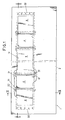
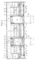
- the Device includes a box-shaped housing 1 with two Side walls 2 and 3, a support tube 4, a Guide rail 5, two units 6, two Drive devices 7, a flexible band 8 to Covering the trajectory and guide assemblies 9 for the ribbon.
- the housing 1 contains a parallel to the path of movement extending opening 10 in a side wall 2.
- the Support tube 4 is attached to holders 11, which in the end of the housing 1 are arranged.
- the guide rail 5 is mounted on the support tube 4.
- each unit 6 two drive units 12 are arranged so that their drive shafts 13 are directed opposite.
- the units 6 are provided with a carriage 14 , which are engaged with the guide rail 5, such that the units 6 are each independently movable on the guide rail 5 back and forth.
- the drive devices 7 are each a unit. 6 assigned and mounted on the holders 11.
- the Drive device 7 includes a drive motor 15 with a drive wheel 16, a pulley 17 and a Drive belt 18, by means of a terminal 19 each is connected to a unit 6.
- the flexible band 8 is in the end of the Movement path attached to the inside of the housing 1.
- elastic elements 20 can be used to keep the band taut.
- the Tape can be made of plastic, coat fabric, metal or Like. Exist.
- the guide assemblies 9 are parallel to each other on the Unit 6 is arranged.
- the guide assembly 9 consists of two holders 21, each with two cylindrical rods 22, the are rotatably arranged in the holders.
- the bars 22 can be arranged in bearings to reduce friction in advantageously reduce.
- the units 6 are from band 8 to three adjacent ones Sides so enclosed that unit 6 through the Opening 10 is freely accessible.
- Each unit 6 may use at least one of the application corresponding device 23 are provided.
- Actuation is the device 23 with the facing Drive unit 12 connected.
- the device shown in Fig. 2A differs from the device according to Figures 1 to 3 characterized in that in the Side walls 2 and 3 each have an opening 10 is formed is, and that two bands 8 for covering the Movement path are provided.
- FIGS. 5 to 6 At a modified version of the device consists of Support tube 4 of two sub-tubes 25 by means of a Butt joint are connected together. These are a connecting part 26, which is partly within the Part pipes 25 is arranged and stud bolts 27 with a conical projection 28 is provided which the Connect connecting part 26 with the partial tubes 25 (Fig.5).
- the connecting part 26 is sleeve-shaped and has two lugs 33, which are arranged in the recess 31, and a Covenant 34 on which the partial tubes 25 with the end faces issue. It is essential here that the turns 31 lower than the lugs 33 are long, and that the Inner diameter of the turns 31 and the Outer diameter of the lugs 33 made as a fit are. In the approaches 33 are radially extending Through holes 35 with a conical countersink 36th formed on the circumference.
- the studs 27 are screwed in, wherein the conical approach 28 of the stud bolts with the countersinks 36 come into operative engagement, so that the sub-pipes 25 against the collar 34 of the connecting part 26 are pressed.
- two sub-pipes 54, 55 are in each case one as a lead and one as a return trained section 56.57 in the end and screws 27 provided for connecting the partial pipes.
Landscapes
- Engineering & Computer Science (AREA)
- Mechanical Engineering (AREA)
- Robotics (AREA)
- General Physics & Mathematics (AREA)
- Pathology (AREA)
- Life Sciences & Earth Sciences (AREA)
- Chemical & Material Sciences (AREA)
- Analytical Chemistry (AREA)
- Biochemistry (AREA)
- General Health & Medical Sciences (AREA)
- Physics & Mathematics (AREA)
- Immunology (AREA)
- Health & Medical Sciences (AREA)
- Mutual Connection Of Rods And Tubes (AREA)
- Auxiliary Devices For Machine Tools (AREA)
- Warehouses Or Storage Devices (AREA)
- Electric Cable Arrangement Between Relatively Moving Parts (AREA)
- Transmission Devices (AREA)
- Control Of Vending Devices And Auxiliary Devices For Vending Devices (AREA)
- Electrophonic Musical Instruments (AREA)
- Facsimile Heads (AREA)
Abstract
Description
- Fig.1
- eine Frontansicht einer ersten Ausführung der Vorrichtung,
- Fig.2
- einen Schnitt entlang der Linie II-II in der Ausführung nach Fig.1,
- Fig.2A
- einen Schnitt entlang der Linie II-II bei einer zweiten Ausführung,
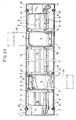
- Fig.3
- einen Schnitt entlang der Linie III-III in Fig.1,
- Fig.4
- einen Schnitt entlang der Linie III-III bei einer modifizierten Ausführung der Vorrichtung,
- Fig.5
- eine Ausführung eines Tragelementes im Schnitt,
- Fig.6
- eine andere Ausführung eines Tragelementes im Schnitt und
- Fig.7
- eine weitere Ausführung eines Tragelementes im Schnitt.
Claims (15)
- Vorrichtung zum Bewegen von mindestens einer Einheit entlang mindestens einer Bewegungsbahn, enthaltend ein Gehäuse(1)mit einer parallel zur Bewegungsbahn verlaufende Öffnung(10), mindestens eine Führungsschiene(5) für die Einheit(6) und mindestens eine Antriebsvorrichtung(7), die mit der Einheit verbunden ist, gekennzeichnet durch mindestens ein flexibles Element(8) zum Abdecken der Bewegungsbahn der Einheit, welches in den Endbereichen der Bewegungsbahn am Gehäuse(1) festgelegt ist und die Einheit teilweise so umgibt, dass die Einheit(6) durch die Öffnung(10) zugänglich ist, und durch Führungsorgane(9) für das flexible Element(8), die drehbar an der Einheit(6) angeordnet sind.
- Vorrichtung nach Anspruch 1, gekennzeichnet durch eine lineare Bewegungsbahn.
- Vorrichtung nach Anspruch 1, dadurch gekennzeichnet, dass das flexible Element(8) bandförmig ist.
- Vorrichtung nach Anspruch 1, dadurch gekennzeichnet, dass mindestens ein elastisches Mittel(17) zur Straffhaltung des Elementes(8) vorgesehen ist.
- Vorrichtung nach Anspruch 1, dadurch gekennzeichnet, dass die Einheit(6) mindestens eine Antriebseinheit(12) aufweist.
- Vorrichtung nach Anspruch 1,dadurch gekennzeichnet, dass die Einheit (6) zwei Antriebseinheiten (12) aufweist.
- Vorrichtung nach Anspruch 1, dadurch gekennzeichnet, dass zwei Einheiten(6) vorgesehen sind, die unabhängig von einander entlang der Führungsschiene(5) bewegbar angeordnet sind.
- Vorrichtung nach Anspruch 1, dadurch gekennzeichnet, dass ein Tragelement(4) für die Einheit(6) im Gehäuse angeordnet ist.
- Vorrichtung nach Anspruch 8, dadurch gekennzeichnet, dass das Tragelement(4) aus einer Mehrzahl von Teilelementen(25) besteht, die mittels einer Stossverbindung miteinander verbunden sind.
- Vorrichtung nach Anspruch 8, dadurch gekennzeichnet, dass das Tragelement(4) ein Rohr ist.
- Vorrichtung nach Anspruch 9 oder 10, dadurch gekennzeichnet, dass die Verbindung zwei erste Teilrohre(25), einen Verbindungsteil(26,51), der mit den Teilrohren(25) in Eingriff ist und Schrauben(27) umfasst, und dass die ersten Teilrohre(25) eine Mehrzahl von Gewindebohrungen(32) und der Verbindungsteil(26,51) eine Mehrzahl von Durchgangsbohrungen(35) aufweisen, die bezüglich den Stossflächen(37) versetzt angeordnet sind.
- Vorrichtung nach Anspruch 11, dadurch gekennzeichnet, dass das Verbindungsteil(26,51) hülsenförmig ausgebildet ist.
- Vorrichtung nach Anspruch 9 oder 10, dadurch gekennzeichnet, dass die Verbindung zwei zweite Teilrohre(44,45) mit jeweils einem als Vorsprung und einem als Rücksprung ausgebildeten Abschnitt(46,47) im Endbereich, die miteinander in Eingriff sind und Schrauben(27) umfasst, und dass im Vorsprung(56) eine Mehrzahl von Gewindebohrungen(32) und im Rücksprung (57) eine Mehrzahl von Durchgangsbohrungen(35) ausgebildet sind, die bezüglich den Stossflächen(37) versetzt angeordnet sind.
- Vorrichtung nach Anspruch 11 oder 13, dadurch gekennzeichnet, dass die Durchgangsbohrungen(35) eine konischen Ansenkung(36) und die Stiftschrauben(27) einen konischen Ansatz(28) aufweisen, der mit der Ansenkung(36) in Wirkeingriff ist, so dass die Teilrohre(25) unter Druck an den Stossflächen(37) anliegen.
- Vorrichtung nach Anspruch 1, gekennzeichnet durch eine kreisförmige Bewegungsbahn.
Priority Applications (3)
| Application Number | Priority Date | Filing Date | Title |
|---|---|---|---|
| AT03405810T ATE333340T1 (de) | 2003-11-13 | 2003-11-13 | Vorrichtung mit einer durch ein flexibles element geschützten linearen bewegungsbahn |
| EP03405810A EP1533073B1 (de) | 2003-11-13 | 2003-11-13 | Vorrichtung mit einer durch ein flexibles Element geschützten linearen Bewegungsbahn |
| DE50304297T DE50304297D1 (de) | 2003-11-13 | 2003-11-13 | Vorrichtung mit einer durch ein flexibles Element geschützten linearen Bewegungsbahn |
Applications Claiming Priority (1)
| Application Number | Priority Date | Filing Date | Title |
|---|---|---|---|
| EP03405810A EP1533073B1 (de) | 2003-11-13 | 2003-11-13 | Vorrichtung mit einer durch ein flexibles Element geschützten linearen Bewegungsbahn |
Publications (2)
| Publication Number | Publication Date |
|---|---|
| EP1533073A1 true EP1533073A1 (de) | 2005-05-25 |
| EP1533073B1 EP1533073B1 (de) | 2006-07-19 |
Family
ID=34429617
Family Applications (1)
| Application Number | Title | Priority Date | Filing Date |
|---|---|---|---|
| EP03405810A Expired - Lifetime EP1533073B1 (de) | 2003-11-13 | 2003-11-13 | Vorrichtung mit einer durch ein flexibles Element geschützten linearen Bewegungsbahn |
Country Status (3)
| Country | Link |
|---|---|
| EP (1) | EP1533073B1 (de) |
| AT (1) | ATE333340T1 (de) |
| DE (1) | DE50304297D1 (de) |
Cited By (5)
| Publication number | Priority date | Publication date | Assignee | Title |
|---|---|---|---|---|
| US7131801B2 (en) * | 2001-02-05 | 2006-11-07 | Renault Automation Comau | Separation device between the machining station and a machine tool driving station |
| CN103949936A (zh) * | 2014-05-13 | 2014-07-30 | 西北工业大学 | 高承载式无限行程导轨防护装置 |
| CN104058238A (zh) * | 2014-07-01 | 2014-09-24 | 苏州博众精工科技有限公司 | 一种自动错位流水线机构 |
| CN104907885A (zh) * | 2015-06-16 | 2015-09-16 | 西北工业大学 | 一种新型高承载式无限行程导轨防护装置 |
| CN107020541A (zh) * | 2017-05-05 | 2017-08-08 | 大连机床(数控)股份有限公司 | 应用动滑轮原理实现差速运动的加工中心防护罩 |
Families Citing this family (1)
| Publication number | Priority date | Publication date | Assignee | Title |
|---|---|---|---|---|
| DE102015119472A1 (de) | 2015-11-11 | 2017-05-11 | Labomatic Instruments Ag | Flüssigkeitshandhabungsvorrichtung |
Citations (7)
| Publication number | Priority date | Publication date | Assignee | Title |
|---|---|---|---|---|
| US3788377A (en) * | 1972-02-01 | 1974-01-29 | Beakbane H Ltd | Corrugated covers for reciprocating machinery parts |
| US4886375A (en) * | 1988-03-09 | 1989-12-12 | Nippon Seiko Kabushiki Kaisha | Dust-proof cover for linear guide |
| EP0407599A1 (de) * | 1988-12-24 | 1991-01-16 | Fanuc Ltd. | Teleskopische abdeckvorrichtung |
| US5125240A (en) * | 1989-08-04 | 1992-06-30 | Cryo-Cell International, Inc. | Storage apparatus, particularly with automatic insertion and retrieval |
| US6241230B1 (en) * | 1999-02-10 | 2001-06-05 | Thk Co., Ltd | Guide apparatus having dustproof structure |
| US6296413B1 (en) * | 1999-10-01 | 2001-10-02 | Central Safety Equipment Company | Mounting clip elements |
| DE10131713A1 (de) * | 2001-06-29 | 2003-01-16 | Sms Demag Ag | Linearführung im Walzwerk |
-
2003
- 2003-11-13 EP EP03405810A patent/EP1533073B1/de not_active Expired - Lifetime
- 2003-11-13 DE DE50304297T patent/DE50304297D1/de not_active Expired - Lifetime
- 2003-11-13 AT AT03405810T patent/ATE333340T1/de not_active IP Right Cessation
Patent Citations (7)
| Publication number | Priority date | Publication date | Assignee | Title |
|---|---|---|---|---|
| US3788377A (en) * | 1972-02-01 | 1974-01-29 | Beakbane H Ltd | Corrugated covers for reciprocating machinery parts |
| US4886375A (en) * | 1988-03-09 | 1989-12-12 | Nippon Seiko Kabushiki Kaisha | Dust-proof cover for linear guide |
| EP0407599A1 (de) * | 1988-12-24 | 1991-01-16 | Fanuc Ltd. | Teleskopische abdeckvorrichtung |
| US5125240A (en) * | 1989-08-04 | 1992-06-30 | Cryo-Cell International, Inc. | Storage apparatus, particularly with automatic insertion and retrieval |
| US6241230B1 (en) * | 1999-02-10 | 2001-06-05 | Thk Co., Ltd | Guide apparatus having dustproof structure |
| US6296413B1 (en) * | 1999-10-01 | 2001-10-02 | Central Safety Equipment Company | Mounting clip elements |
| DE10131713A1 (de) * | 2001-06-29 | 2003-01-16 | Sms Demag Ag | Linearführung im Walzwerk |
Cited By (6)
| Publication number | Priority date | Publication date | Assignee | Title |
|---|---|---|---|---|
| US7131801B2 (en) * | 2001-02-05 | 2006-11-07 | Renault Automation Comau | Separation device between the machining station and a machine tool driving station |
| CN103949936A (zh) * | 2014-05-13 | 2014-07-30 | 西北工业大学 | 高承载式无限行程导轨防护装置 |
| CN104058238A (zh) * | 2014-07-01 | 2014-09-24 | 苏州博众精工科技有限公司 | 一种自动错位流水线机构 |
| CN104058238B (zh) * | 2014-07-01 | 2016-04-06 | 苏州博众精工科技有限公司 | 一种自动错位流水线机构 |
| CN104907885A (zh) * | 2015-06-16 | 2015-09-16 | 西北工业大学 | 一种新型高承载式无限行程导轨防护装置 |
| CN107020541A (zh) * | 2017-05-05 | 2017-08-08 | 大连机床(数控)股份有限公司 | 应用动滑轮原理实现差速运动的加工中心防护罩 |
Also Published As
| Publication number | Publication date |
|---|---|
| DE50304297D1 (de) | 2006-08-31 |
| EP1533073B1 (de) | 2006-07-19 |
| ATE333340T1 (de) | 2006-08-15 |
Similar Documents
| Publication | Publication Date | Title |
|---|---|---|
| DE112016001927B4 (de) | Führungsvorrichtung für ein langes Objekt und Befestigungselement | |
| DE102013004824B4 (de) | Versorgungselement-Führungsmechanismus am Vorderende eines Handgelenks eines Industrieroboters | |
| EP2557059A1 (de) | Fördereinrichtung umfassend eine Hub-Quereinheit mit Förderrollen | |
| EP2069113A1 (de) | Vorrichtung zum führen eines zumindest eine versorgungsleitung aufweisenden schlauches | |
| DE2933704A1 (de) | Druckmittelverbindung zwischen einem ventilblock und einem zumindest einen doppelt wirkenden druckmittelmotor aufweisenden verbraucher | |
| EP0607957B1 (de) | Bausatz zur Standardisierung und Bildung eines Baukastensystems für Kettenförderer, Kettenstauförderer und/oder Zahnriemenförderer | |
| EP2143670A2 (de) | Modularer Bandförderer | |
| EP1533073B1 (de) | Vorrichtung mit einer durch ein flexibles Element geschützten linearen Bewegungsbahn | |
| DE102004030858B3 (de) | Beschichtungsanlage und zugehöriges Betriebsverfahren | |
| DE112015001794B4 (de) | Führungsmechanismus und Verfahren zu dessen Herstellung | |
| DE102007017997A1 (de) | Verstelleinheit | |
| EP1729389A1 (de) | Leitungsführungeinrichtung für biegbare elektrische oder fluidische Leitungen | |
| EP4045819B1 (de) | Antriebssystem | |
| EP0623533A1 (de) | Verfahren und Fördereinrichtung zum Transportieren von Werkstückträgern | |
| EP3471905A1 (de) | Kupplungsvorrichtung zum verbinden langgestreckter hohlkörper in einem montagesystem | |
| DE29607172U1 (de) | Zugentlastung | |
| DE10239819B4 (de) | Vorrichtung zum Spannen eines flexiblen Fördermittels | |
| DE19853408B4 (de) | Anlage zur Bearbeitung und/oder Montage von Bauteilen | |
| DE202006008714U1 (de) | Linearführung | |
| DE102006017456A1 (de) | Mehrachsenanordnung von Lineareinheiten, insbesondere zur Bildung eines Linearsystems für Materialfluss- und Fertigungseinrichtungen | |
| DE102013220496B4 (de) | Umformmaschine , insbesondere Presse zum Umformen von Werkstücken | |
| EP0620397A1 (de) | Tragvorrichtung | |
| EP4459135A1 (de) | Befestigungselement eines t-förmigen profilschlauchs, verbindungsanordnung mit dem befestigungselement, setzgerät sowie herstellungs- und verbindungsverfahren | |
| DE102015113768B4 (de) | Handhabungsvorrichtung und Verwendung einer solchen | |
| EP1249410A2 (de) | Vorrichtung mit einer Plattform, einem Stützkörper und Luftpolstererzeugungsmitteln |
Legal Events
| Date | Code | Title | Description |
|---|---|---|---|
| PUAI | Public reference made under article 153(3) epc to a published international application that has entered the european phase |
Free format text: ORIGINAL CODE: 0009012 |
|
| 17P | Request for examination filed |
Effective date: 20040621 |
|
| AK | Designated contracting states |
Kind code of ref document: A1 Designated state(s): AT BE BG CH CY CZ DE DK EE ES FI FR GB GR HU IE IT LI LU MC NL PT RO SE SI SK TR |
|
| AX | Request for extension of the european patent |
Extension state: AL LT LV MK |
|
| GRAP | Despatch of communication of intention to grant a patent |
Free format text: ORIGINAL CODE: EPIDOSNIGR1 |
|
| GRAS | Grant fee paid |
Free format text: ORIGINAL CODE: EPIDOSNIGR3 |
|
| AKX | Designation fees paid |
Designated state(s): AT BE BG CH CY CZ DE DK EE ES FI FR GB GR HU IE IT LI LU MC NL PT RO SE SI SK TR |
|
| GRAA | (expected) grant |
Free format text: ORIGINAL CODE: 0009210 |
|
| AK | Designated contracting states |
Kind code of ref document: B1 Designated state(s): AT BE BG CH CY CZ DE DK EE ES FI FR GB GR HU IE IT LI LU MC NL PT RO SE SI SK TR |
|
| PG25 | Lapsed in a contracting state [announced via postgrant information from national office to epo] |
Ref country code: IT Free format text: LAPSE BECAUSE OF FAILURE TO SUBMIT A TRANSLATION OF THE DESCRIPTION OR TO PAY THE FEE WITHIN THE PRESCRIBED TIME-LIMIT;WARNING: LAPSES OF ITALIAN PATENTS WITH EFFECTIVE DATE BEFORE 2007 MAY HAVE OCCURRED AT ANY TIME BEFORE 2007. THE CORRECT EFFECTIVE DATE MAY BE DIFFERENT FROM THE ONE RECORDED. Effective date: 20060719 Ref country code: CZ Free format text: LAPSE BECAUSE OF FAILURE TO SUBMIT A TRANSLATION OF THE DESCRIPTION OR TO PAY THE FEE WITHIN THE PRESCRIBED TIME-LIMIT Effective date: 20060719 Ref country code: SK Free format text: LAPSE BECAUSE OF FAILURE TO SUBMIT A TRANSLATION OF THE DESCRIPTION OR TO PAY THE FEE WITHIN THE PRESCRIBED TIME-LIMIT Effective date: 20060719 Ref country code: NL Free format text: LAPSE BECAUSE OF FAILURE TO SUBMIT A TRANSLATION OF THE DESCRIPTION OR TO PAY THE FEE WITHIN THE PRESCRIBED TIME-LIMIT Effective date: 20060719 Ref country code: SI Free format text: LAPSE BECAUSE OF FAILURE TO SUBMIT A TRANSLATION OF THE DESCRIPTION OR TO PAY THE FEE WITHIN THE PRESCRIBED TIME-LIMIT Effective date: 20060719 Ref country code: RO Free format text: LAPSE BECAUSE OF FAILURE TO SUBMIT A TRANSLATION OF THE DESCRIPTION OR TO PAY THE FEE WITHIN THE PRESCRIBED TIME-LIMIT Effective date: 20060719 Ref country code: FI Free format text: LAPSE BECAUSE OF FAILURE TO SUBMIT A TRANSLATION OF THE DESCRIPTION OR TO PAY THE FEE WITHIN THE PRESCRIBED TIME-LIMIT Effective date: 20060719 Ref country code: IE Free format text: LAPSE BECAUSE OF FAILURE TO SUBMIT A TRANSLATION OF THE DESCRIPTION OR TO PAY THE FEE WITHIN THE PRESCRIBED TIME-LIMIT Effective date: 20060719 |
|
| REG | Reference to a national code |
Ref country code: GB Ref legal event code: FG4D Free format text: NOT ENGLISH |
|
| GBT | Gb: translation of ep patent filed (gb section 77(6)(a)/1977) |
Effective date: 20060719 |
|
| REG | Reference to a national code |
Ref country code: CH Ref legal event code: EP |
|
| REG | Reference to a national code |
Ref country code: IE Ref legal event code: FG4D Free format text: LANGUAGE OF EP DOCUMENT: GERMAN |
|
| REF | Corresponds to: |
Ref document number: 50304297 Country of ref document: DE Date of ref document: 20060831 Kind code of ref document: P |
|
| PG25 | Lapsed in a contracting state [announced via postgrant information from national office to epo] |
Ref country code: SE Free format text: LAPSE BECAUSE OF FAILURE TO SUBMIT A TRANSLATION OF THE DESCRIPTION OR TO PAY THE FEE WITHIN THE PRESCRIBED TIME-LIMIT Effective date: 20061019 Ref country code: DK Free format text: LAPSE BECAUSE OF FAILURE TO SUBMIT A TRANSLATION OF THE DESCRIPTION OR TO PAY THE FEE WITHIN THE PRESCRIBED TIME-LIMIT Effective date: 20061019 Ref country code: BG Free format text: LAPSE BECAUSE OF FAILURE TO SUBMIT A TRANSLATION OF THE DESCRIPTION OR TO PAY THE FEE WITHIN THE PRESCRIBED TIME-LIMIT Effective date: 20061019 |
|
| PG25 | Lapsed in a contracting state [announced via postgrant information from national office to epo] |
Ref country code: ES Free format text: LAPSE BECAUSE OF FAILURE TO SUBMIT A TRANSLATION OF THE DESCRIPTION OR TO PAY THE FEE WITHIN THE PRESCRIBED TIME-LIMIT Effective date: 20061030 |
|
| PG25 | Lapsed in a contracting state [announced via postgrant information from national office to epo] |
Ref country code: BE Free format text: LAPSE BECAUSE OF NON-PAYMENT OF DUE FEES Effective date: 20061130 Ref country code: MC Free format text: LAPSE BECAUSE OF NON-PAYMENT OF DUE FEES Effective date: 20061130 |
|
| PG25 | Lapsed in a contracting state [announced via postgrant information from national office to epo] |
Ref country code: PT Free format text: LAPSE BECAUSE OF FAILURE TO SUBMIT A TRANSLATION OF THE DESCRIPTION OR TO PAY THE FEE WITHIN THE PRESCRIBED TIME-LIMIT Effective date: 20061219 |
|
| NLV1 | Nl: lapsed or annulled due to failure to fulfill the requirements of art. 29p and 29m of the patents act | ||
| ET | Fr: translation filed | ||
| PGFP | Annual fee paid to national office [announced via postgrant information from national office to epo] |
Ref country code: IE Payment date: 20070129 Year of fee payment: 4 |
|
| REG | Reference to a national code |
Ref country code: IE Ref legal event code: FD4D |
|
| PLBE | No opposition filed within time limit |
Free format text: ORIGINAL CODE: 0009261 |
|
| STAA | Information on the status of an ep patent application or granted ep patent |
Free format text: STATUS: NO OPPOSITION FILED WITHIN TIME LIMIT |
|
| 26N | No opposition filed |
Effective date: 20070420 |
|
| BERE | Be: lapsed |
Owner name: MARCHAND, CLAUDE Effective date: 20061130 |
|
| PG25 | Lapsed in a contracting state [announced via postgrant information from national office to epo] |
Ref country code: AT Free format text: LAPSE BECAUSE OF NON-PAYMENT OF DUE FEES Effective date: 20061113 |
|
| PG25 | Lapsed in a contracting state [announced via postgrant information from national office to epo] |
Ref country code: GR Free format text: LAPSE BECAUSE OF FAILURE TO SUBMIT A TRANSLATION OF THE DESCRIPTION OR TO PAY THE FEE WITHIN THE PRESCRIBED TIME-LIMIT Effective date: 20061020 |
|
| PG25 | Lapsed in a contracting state [announced via postgrant information from national office to epo] |
Ref country code: EE Free format text: LAPSE BECAUSE OF FAILURE TO SUBMIT A TRANSLATION OF THE DESCRIPTION OR TO PAY THE FEE WITHIN THE PRESCRIBED TIME-LIMIT Effective date: 20060719 |
|
| PG25 | Lapsed in a contracting state [announced via postgrant information from national office to epo] |
Ref country code: LU Free format text: LAPSE BECAUSE OF NON-PAYMENT OF DUE FEES Effective date: 20061113 Ref country code: TR Free format text: LAPSE BECAUSE OF FAILURE TO SUBMIT A TRANSLATION OF THE DESCRIPTION OR TO PAY THE FEE WITHIN THE PRESCRIBED TIME-LIMIT Effective date: 20060719 Ref country code: HU Free format text: LAPSE BECAUSE OF FAILURE TO SUBMIT A TRANSLATION OF THE DESCRIPTION OR TO PAY THE FEE WITHIN THE PRESCRIBED TIME-LIMIT Effective date: 20070120 |
|
| PG25 | Lapsed in a contracting state [announced via postgrant information from national office to epo] |
Ref country code: CY Free format text: LAPSE BECAUSE OF FAILURE TO SUBMIT A TRANSLATION OF THE DESCRIPTION OR TO PAY THE FEE WITHIN THE PRESCRIBED TIME-LIMIT Effective date: 20060719 |
|
| REG | Reference to a national code |
Ref country code: FR Ref legal event code: PLFP Year of fee payment: 13 |
|
| REG | Reference to a national code |
Ref country code: FR Ref legal event code: PLFP Year of fee payment: 14 |
|
| REG | Reference to a national code |
Ref country code: FR Ref legal event code: PLFP Year of fee payment: 15 |
|
| REG | Reference to a national code |
Ref country code: CH Ref legal event code: PL |
|
| PG25 | Lapsed in a contracting state [announced via postgrant information from national office to epo] |
Ref country code: CH Free format text: LAPSE BECAUSE OF NON-PAYMENT OF DUE FEES Effective date: 20201130 Ref country code: LI Free format text: LAPSE BECAUSE OF NON-PAYMENT OF DUE FEES Effective date: 20201130 |
|
| PGFP | Annual fee paid to national office [announced via postgrant information from national office to epo] |
Ref country code: IT Payment date: 20221124 Year of fee payment: 20 Ref country code: GB Payment date: 20221125 Year of fee payment: 20 Ref country code: FR Payment date: 20221128 Year of fee payment: 20 |
|
| PGFP | Annual fee paid to national office [announced via postgrant information from national office to epo] |
Ref country code: CH Payment date: 20221201 Year of fee payment: 20 |
|
| PGFP | Annual fee paid to national office [announced via postgrant information from national office to epo] |
Ref country code: DE Payment date: 20230127 Year of fee payment: 20 |
|
| REG | Reference to a national code |
Ref country code: DE Ref legal event code: R071 Ref document number: 50304297 Country of ref document: DE |
|
| REG | Reference to a national code |
Ref country code: CH Ref legal event code: PL |
|
| REG | Reference to a national code |
Ref country code: GB Ref legal event code: PE20 Expiry date: 20231112 |
|
| PG25 | Lapsed in a contracting state [announced via postgrant information from national office to epo] |
Ref country code: GB Free format text: LAPSE BECAUSE OF EXPIRATION OF PROTECTION Effective date: 20231112 |
|
| PG25 | Lapsed in a contracting state [announced via postgrant information from national office to epo] |
Ref country code: GB Free format text: LAPSE BECAUSE OF EXPIRATION OF PROTECTION Effective date: 20231112 |