EP1532307B1 - Umbrella-type clothes drier comprising a protective cover - Google Patents
Umbrella-type clothes drier comprising a protective cover Download PDFInfo
- Publication number
- EP1532307B1 EP1532307B1 EP03797241A EP03797241A EP1532307B1 EP 1532307 B1 EP1532307 B1 EP 1532307B1 EP 03797241 A EP03797241 A EP 03797241A EP 03797241 A EP03797241 A EP 03797241A EP 1532307 B1 EP1532307 B1 EP 1532307B1
- Authority
- EP
- European Patent Office
- Prior art keywords
- protective cover
- standpipe
- upright tube
- cover
- retracted
- Prior art date
- Legal status (The legal status is an assumption and is not a legal conclusion. Google has not performed a legal analysis and makes no representation as to the accuracy of the status listed.)
- Expired - Lifetime
Links
Images
Classifications
-
- D—TEXTILES; PAPER
- D06—TREATMENT OF TEXTILES OR THE LIKE; LAUNDERING; FLEXIBLE MATERIALS NOT OTHERWISE PROVIDED FOR
- D06F—LAUNDERING, DRYING, IRONING, PRESSING OR FOLDING TEXTILE ARTICLES
- D06F57/00—Supporting means, other than simple clothes-lines, for linen or garments to be dried or aired
- D06F57/02—Supporting means, other than simple clothes-lines, for linen or garments to be dried or aired mounted on pillars, e.g. rotatably
- D06F57/04—Supporting means, other than simple clothes-lines, for linen or garments to be dried or aired mounted on pillars, e.g. rotatably and having radial arms, e.g. collapsible
Definitions
- the protective cover fabric bags may be appropriate, in which stiff, sheet-shaped, protruding from the fabric pockets cover parts are added, which are pushed laterally from the retracted into the standpipe cover over the upper opening of the standpipe and completely cover when the protective cover has been completely withdrawn into the standpipe.
Landscapes
- Engineering & Computer Science (AREA)
- Textile Engineering (AREA)
- Holders For Apparel And Elements Relating To Apparel (AREA)
- Drying Of Solid Materials (AREA)
- Walking Sticks, Umbrellas, And Fans (AREA)
- Centrifugal Separators (AREA)
Abstract
Description
Die Erfindung betrifft einen schirmartigen Wäschetrockner, bei dem auf einem zentralen Standrohr ein auseinanderklappbares und wieder zusammenklappbares, die Wäscheleine tragendes Spreizgestell vorzugsweise verstellbar angeordnet und eine aus dem Standrohr heraus über das zusammengeklappte Spreizgestell und die Wäscheleine überziehbare Schutzhülle vorgesehen ist, die an ihrem im Standrohr verbleibenden, inneren Endabschnitt in das Standrohr wieder zurückziehbar ist.The invention relates to a screen-type clothes dryer, in which on a central standpipe auseinanderklappbares and again collapsible, the clothesline supporting spreader frame preferably arranged adjustable and provided from the standpipe on the folded spreader frame and the clothesline protective cover is provided, remaining at its in the standpipe , Inner end portion in the standpipe is retractable.
Ein solcher Wäschetrockner ist beispielsweise aus der
Bei dem bekannten Wäschetrockner ist am Aufstellungsort bei der für die Verankerung seines Standrohres im Boden erforderlichen Bodenhülse dafür zu sorgen, dass in das Standrohr eindringendes Regenwasser im Bereich der Bodenhülse im Boden versickern kann.In the case of the known tumble dryer, it is necessary to ensure at the place of installation at the ground socket required for the anchoring of its standpipe in the ground, that rainwater entering the standpipe can seep into the ground in the area of the ground socket.
Aufgabe der Erfindung ist es, einen verbesserten schirmartigen Wäschetrockner der eingangs genannten Art anzugeben.The object of the invention is to provide an improved umbrella-type clothes dryer of the type mentioned.
Dies wird erfindungsgemäß dadurch erreicht, dass die Schutzhülle an ihrem äußeren Endabschnitt eine, bei in das Standrohr zurückgezogener Schutzhülle, die Oberseite des Standrohres übergreifende Abdeckung trägt.This is inventively achieved in that the protective cover carries at its outer end portion a, retracted in the standpipe protective cover, the top of the standpipe cross-cover.
Mit der mit der Schutzhülle mitbewegbaren Abdeckung, die sich bei in das Standrohr zurückgezogener Schutzhülle über das obere Ende des Standrohres legt, wird verhindert, dass bei aufgespanntem Wäschetrockner Schmutz und Regenwasser ins Innere des Standrohres oder der dorthin zurückgezogenen Schutzhülle gelangen können und später, wenn die Schutzhülle über das zusammengeklappte Spreizgestell übergezogen wird, an der Außenseite der den zusammengeklappten Wäschetrockner umgebenden Schutzhülle herunter rinnen können. Ein weiterer Vorteil dieser Ausbildung besteht darin, dass am Aufstellungsort des Wäschetrockners bei der für die Verankerung seines Standrohres erforderlichen Bodenhülse bei deren Herstellung bzw. Einbringung in den Boden keine baulichen Vorkehrungen für das Versickern des Regenwassers im Boden getroffen werden müssen.Mitbewegbaren with the protective cover, which lays in retracted into the standpipe cover over the upper end of the standpipe, prevents dirt and rainwater can reach inside the standpipe or retracted there protective cover with spanned dryer and later, if the Protective cover is pulled over the folded spreader, can run down on the outside of the protective bag surrounding the folded tumble dryer. Another advantage of this design is that no structural precautions have to be taken for the infiltration of rainwater in the ground at the site of the tumble dryer when required for the anchoring of its standpipe ground sleeve during their production or introduction into the ground.
Erfindungsgemäß kann eine mit dem äußeren Endabschnitt der Schutzhülle verbundene Abdeckklappe als Abdeckung vorgesehen sein.According to the invention, a cover flap connected to the outer end portion of the protective cover may be provided as a cover.
Die Abdeckklappe ist am äußeren Endabschnitt der Schutzhülle an der Außenseite der Schutzhülle seitlich angebracht. Sie steht dort nach oben ab und wird am oberen Ende des Standrohres, wo die Schutzhülle um 180 ° ins Innere des Standrohres umgelenkt wird, von der unter ihr ins Standrohr eingezogenen Schutzhülle über das obere Ende des Standrohres geschoben. Bei in das Standrohr vollständig zurückgezogener Schutzhülle übergreift die Abdeckklappe das obere Standrohrende und deckt dessen Öffnung nach oben ab.The cover flap is laterally attached to the outer end portion of the protective cover on the outside of the protective cover. She stands there from above and is pushed at the upper end of the standpipe, where the protective cover is deflected by 180 ° into the interior of the standpipe, drawn from under her protective tube in the standpipe over the upper end of the standpipe. When fully retracted into the standpipe protective cover over the cover flap engages the upper standpipe end and covers the opening from above.
Die mit der Schutzhülle mitbewegbaren Abdeckung kann auch aus zwei, an gegenüberliegenden Stellen des äußeren Endabschnittes der Schutzhülle seitlich angebrachten Klappen bestehen, die am oberen Ende des Standrohres von der unter ihnen ins Standrohr eingezogenen Schutzhülle von gegenüberliegenden Seiten über das obere Ende des Standrohres geschoben werden. Dabei können die beiden Klappen mit ihren Stirnkanten aneinander stoßen und dadurch das Einziehen der Schutzhülle in das Standrohr beenden. Die beiden Klappen können einander gegenseitig zugeordnete Anschläge besitzen, mit denen sie aufeinander treffen während sie von der unter ihnen ins Standrohr eingezogenen Schutzhülle von gegenüberliegenden Seiten über das obere Ende des Standrohres geschoben werden. Durch das Aufeinandertreffen der Anschläge der beiden Klappen wird das Einziehen der Schutzhülle in das Standrohr beendet, während die sich die stirnseitigen Endabschnitte der beiden Klappen überlappen.Mitbewegbaren with the protective cover can also consist of two, at opposite locations of the outer end portion of the protective cover laterally mounted flaps, which at the upper end of the standpipe of the under they are pulled into the standpipe protective cover pushed from opposite sides over the upper end of the standpipe. In this case, the two flaps can abut each other with their end edges and thereby terminate the pulling of the protective cover in the standpipe. The two flaps may have mutually associated stops, with which they meet each other while they are pushed by the under them retracted into the standpipe protective cover from opposite sides over the upper end of the standpipe. By the meeting of the stops of the two flaps, the retraction of the protective cover is terminated in the standpipe, while overlapping the front end portions of the two flaps.
Gemäß einem weiteren Merkmal der Erfindung kann eine zumindest zweiteilige Abdeckung mit dem äußeren Endabschnitt der Schutzhülle verbunden sein, deren Abdeckteile um den äußeren Endabschnitt der Schutzhülle herum verteilt angeordnet sind und bei in das Standrohr zurückgezogener Schutzhülle die obere Öffnung des Standrohres gemeinsam abdecken.According to a further feature of the invention, an at least two-part cover may be connected to the outer end portion of the protective cover, the cover parts are distributed around the outer end portion of the protective cover around and cover the upper opening of the standpipe together with withdrawn in the standpipe cover.
Am äußeren Endabschnitt der Schutzhülle können Stofftaschen angebracht sein, in denen steife, blattförmige, aus den Stofftaschen vorstehende Abdeckteile aufgenommen sind, die von der zurück in das Standrohr eingezogenen Schutzhülle über die obere Öffnung des Standrohres seitlich vorgeschoben werden und die vollständig abdecken, wenn die Schutzhülle vollständig in das Standrohr zurückgezogen worden ist.At the outer end portion of the protective cover fabric bags may be appropriate, in which stiff, sheet-shaped, protruding from the fabric pockets cover parts are added, which are pushed laterally from the retracted into the standpipe cover over the upper opening of the standpipe and completely cover when the protective cover has been completely withdrawn into the standpipe.
Erfindungsgemäß können die bei in das Standrohr zurückgezogener Schutzhülle die Oberseite des Standrohres gemeinsam abdeckenden Abdeckteile einander gegenseitig zumindest teilweise überlappen. Diese Ausbildung erlaubt größere Toleranzen sowohl bei der Herstellung dieser Abdeckteile als auch bei deren Befestigung an der Schutzhülle.According to the invention, when the protective cover is pulled back into the standpipe, the cover parts covering the upper side of the standpipe mutually overlap one another at least partially. This design allows greater tolerances both in the production of these cover parts as well as their attachment to the protective cover.
Nachstehend wird die Erfindung an Ausführungsbeispielen anhand der Zeichnungen näher erläutert.The invention of exemplary embodiments will be explained in more detail with reference to the drawings.
In den Zeichnungen zeigen:
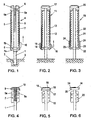
- Fig. 1
- einen schirmartigen Wäschetrockner mit zusammengeklapptem Spreizge-stell, übergezogener Schutzhülle und einteiliger Abdeckklappe,
- Fig. 2
- einen schirmartigen Wäschetrockner mit zusammengeklapptem Spreizgestell, übergezogener Schutzhülle und zweiteiliger Abdeckklappe,
- Fig. 3
- einen schirmartigen Wäschetrockner mit zusammengeklapptem Spreizgestell, übergezogener Schutzhülle und aus Stofftaschen herausstehenden Abdeckteilen,
- Fig. 4
- den oberen Endabschnitt eines schirmartigen Wäschetrockners mit zusammengeklapptem Spreizgestell, in das Standrohr zurückgezogener Schutzhülle und einer die Oberseite des Standrohres überdeckenden, einteiligen Abdeckklappe
- Fig. 5
- den oberen Endabschnitt eines schirmartigen Wäschetrockners mit zusammengeklapptem Spreizgestell, in das Standrohr zurückgezogener Schutzhülle und einer zweiteiligen, die Oberseite des Standrohres überdeckenden Abdeckklappe, und
- Fig. 6
- den oberen Endabschnitt eines schirmartigen Wäschetrockners mit zusammengeklapptem Spreizgestell, in das Standrohr zurückgezogener Schutzhülle und die Oberseite des Standrohres überdeckenden, aus Stofftaschen herausstehenden Abdeckteilen.
- Fig. 1
- a screen-type dryer with folded Spreizge-stell, Covered protective cover and one-piece cover flap,
- Fig. 2
- a screen-type clothes dryer with folded spreader frame, covered protective cover and two-part cover flap,
- Fig. 3
- a screen-type clothes dryer with folded spreader frame, protective cover and cover parts protruding from fabric pockets,
- Fig. 4
- the upper end portion of a screen-like tumble dryer with folded spreader frame, in the standpipe retracted protective cover and the top of the standpipe covering, one-piece cover flap
- Fig. 5
- the upper end portion of a screen-like clothes dryer with folded expansion frame, in the standpipe retracted protective cover and a two-part, the top of the standpipe covering the cover flap, and
- Fig. 6
- the upper end portion of a screen-like tumble dryer with folded expansion frame, in the standpipe retracted protective cover and the top of the standpipe covering, protruding from fabric pockets cover parts.
Im Standrohr 1 ist eine schlauchförmige Schutzhülle 7 untergebracht, die sich im Standrohr 1 von einem Gewichtstück 8 nach oben zum oberen Ende des Standroh-res 1 erstreckt, wo sie eine bis über das zusammengeklappte Spreizgestell 5 nach außen vorstehende, trompetenförmige Umlenkhülse 9 passiert, die die Schutzhülle 7 mit ihrer Innenseite nach außen wendet, während sie an der Außenseite des zusammengeklappten Spreizgestelles 5 über die in kurzen Schlingen von den Tragarmen 5 herunterhängende Wäscheleine hinweg nach unten gezogen und schließlich unterhalb der unteren Hülse 6 des Spreizgestelles 5 am Standrohr 1 festgebunden wird.. Die Schutzhülle 7 trägt an ihrem die untere Hülse 6 des Spreizgestelles 5 von oben nach unten übergreifenden, äußeren Endabschnitt 7a eine von diesem nach oben abstehende, seitliche Abdeckklappe 10, die bei in das Standrohr 1 zurückgezogener Schutzhülle 7, die Oberseite des Standrohres 1 übergreift (
Wird die über das zusammengeklappte Spreizgestell 5 übergezogene Schutzhülle 7 unterhalb des Spreizgestelles 5 vom Standrohr 1 gelöst und damit freigegeben, so zieht das im Standrohr 1 nach unten fallende Gewichtstück 8 die Schutzhülle 7 vom zusammengeklappten Spreizgestell 5 nach oben ab und die Schutzhülle 7 wird am oberen Ende des Standrohres 1 von der trompetenförmigen Umlenkhülse 9 um 180 ° ins Innere des Standrohres 1 umgelenkt. Die am äußeren Endabschnitt 7a der Schutzhülle 7 angebrachte Abdeckklappe 10 wird von der unter ihr ins Standrohr 1 eingezogenen Schutzhülle 7 oberhalb der trompetenförmigen Umlenkhülse 9 über das obere Ende des Standrohres 1 geschoben und deckt die trompetenförmige Umlenkhülse 9 und das Standrohr 1 bei vollständig in das Standrohr 1 zurückgezogener Schutzhülle 7 nach oben ab.If the over the folded
Die
Die
Claims (4)
- An umbrella-type clothes drier (4, 11, 19), wherein on a central upright tube (1) there is arranged, preferably in an adjustable manner, a spreading frame (5, 12, 20) which can be unfolded away from the upright tube (1) and folded towards it and supports the clothes line, and there is provided a protective cover (7, 13, 21) that can be pulled out of the upright tube (1) over the folded spreading frame (5, 12, 20) and the clothes line and at its inner end section remaining in the upright tube (1) can be retracted back into the upright tube (1), characterised in that the protective cover (7, 13, 21) at its outer end section (7a, 14, 22) bears a covering (10, 15, 16, 24) which engages over the upper side of the upright tube (1) when the protective cover (7, 13, 21) is retracted into the upright tube (1).
- A clothes drier (4, 11, 19) according to claim 1, characterised in that at least one covering flap (10, 15, 16, 24), which is connected to the outer end section (7a, 14, 22) of the protective cover (7, 13, 21) preferably in a movable manner, is provided as a covering (10, 15, 16, 24).
- A clothes drier (11, 19) according to claim 1, characterised in that connected to the outer end section (14, 22) of the protective cover (13, 21) there is a covering (15, 16, 24) that is in at least two parts and whose covering portions (15, 16, 24) are arranged so that they are distributed around the outer end section (14, 22) of the protective cover (13, 21) and when the protective cover (13, 21) is retracted into the upright tube (1) jointly cover the upper opening of the upright tube (1).
- A clothes drier (11, 19) according to claim 3, characterised in that the covering portions (15, 16, 24), jointly covering the upper side of the upright tube (1) when the protective cover (13, 21) is retracted into the upright tube (1), mutually overlap each other at least in part.
Applications Claiming Priority (3)
| Application Number | Priority Date | Filing Date | Title |
|---|---|---|---|
| AT12642002 | 2002-08-23 | ||
| AT0126402A AT412881B (en) | 2002-08-23 | 2002-08-23 | SHIELDED DRYER WITH PROTECTIVE CASING |
| PCT/EP2003/008991 WO2004027141A1 (en) | 2002-08-23 | 2003-08-13 | Umbrella-type clothes drier comprising a protective cover |
Publications (2)
| Publication Number | Publication Date |
|---|---|
| EP1532307A1 EP1532307A1 (en) | 2005-05-25 |
| EP1532307B1 true EP1532307B1 (en) | 2008-09-03 |
Family
ID=31999986
Family Applications (1)
| Application Number | Title | Priority Date | Filing Date |
|---|---|---|---|
| EP03797241A Expired - Lifetime EP1532307B1 (en) | 2002-08-23 | 2003-08-13 | Umbrella-type clothes drier comprising a protective cover |
Country Status (6)
| Country | Link |
|---|---|
| US (1) | US7000788B2 (en) |
| EP (1) | EP1532307B1 (en) |
| AT (2) | AT412881B (en) |
| AU (1) | AU2003255436A1 (en) |
| DE (1) | DE50310444D1 (en) |
| WO (1) | WO2004027141A1 (en) |
Cited By (1)
| Publication number | Priority date | Publication date | Assignee | Title |
|---|---|---|---|---|
| DE202012012638U1 (en) | 2012-12-14 | 2013-08-14 | Carl Freudenberg Kg | Clothesline with protection |
Families Citing this family (7)
| Publication number | Priority date | Publication date | Assignee | Title |
|---|---|---|---|---|
| US7159099B2 (en) * | 2002-06-28 | 2007-01-02 | Motorola, Inc. | Streaming vector processor with reconfigurable interconnection switch |
| AT413547B (en) * | 2003-08-19 | 2006-03-15 | Wuester Heinrich | SHINY DRIER |
| AT413987B (en) * | 2003-08-29 | 2006-08-15 | Wuester Heinrich | SHINY DRIER |
| AT502115B8 (en) * | 2005-07-14 | 2007-08-15 | Wuester Heinrich | SHIELDED DRYER WITH ACTUATOR |
| US20080235979A1 (en) * | 2007-03-27 | 2008-10-02 | Meecham Michael D | Hi-N-Dri |
| US8161990B1 (en) | 2010-07-01 | 2012-04-24 | Coletta Anthony J | Clothesline cover apparatus |
| DE102011114513A1 (en) | 2011-09-29 | 2013-04-04 | Carl Freudenberg Kg | Clothesline with protection |
Family Cites Families (11)
| Publication number | Priority date | Publication date | Assignee | Title |
|---|---|---|---|---|
| US483275A (en) * | 1892-09-27 | Hattie adler | ||
| US2443772A (en) * | 1945-01-18 | 1948-06-22 | Mappin Walter Levison | Collapsible umbrella |
| US2784848A (en) * | 1953-06-10 | 1957-03-12 | Senne Edgar Peter | Collapsible disappearing radial arm mechanism |
| US3069021A (en) * | 1959-01-29 | 1962-12-18 | Ruth C Gray | Garment drying apparatus |
| US3490469A (en) * | 1967-11-08 | 1970-01-20 | Emanuel Dubinsky | Umbrella cover |
| US3920127A (en) * | 1975-03-05 | 1975-11-18 | Louis J Labeaud | Folding rack for clothes hangers |
| AU526456B2 (en) * | 1977-12-12 | 1983-01-13 | Gordon Hildreth William | Clotheslines |
| AT384718B (en) | 1985-09-04 | 1987-12-28 | Wuester Heinrich | PROTECTIVE COVER FOR UMBRELLA-LIKE DRYER OR GARDEN UMBRELLAS |
| DE3870234D1 (en) * | 1988-07-29 | 1992-05-21 | Leifheit Ag | LINEN PROTECTION FOR UMBRELLA-DRESSED DRYERS. |
| DE19644532C1 (en) * | 1996-10-26 | 1998-05-14 | Sonetta Gmbh | Rotary outdoor washing line |
| DE20102927U1 (en) * | 2001-02-19 | 2001-11-08 | Milde Dietger | Weather protection screen for tumble dryers |
-
2002
- 2002-08-23 AT AT0126402A patent/AT412881B/en not_active IP Right Cessation
-
2003
- 2003-08-13 EP EP03797241A patent/EP1532307B1/en not_active Expired - Lifetime
- 2003-08-13 WO PCT/EP2003/008991 patent/WO2004027141A1/en active IP Right Grant
- 2003-08-13 AT AT03797241T patent/ATE407251T1/en not_active IP Right Cessation
- 2003-08-13 DE DE50310444T patent/DE50310444D1/en not_active Expired - Lifetime
- 2003-08-13 AU AU2003255436A patent/AU2003255436A1/en not_active Abandoned
-
2005
- 2005-02-18 US US11/061,594 patent/US7000788B2/en not_active Expired - Lifetime
Cited By (2)
| Publication number | Priority date | Publication date | Assignee | Title |
|---|---|---|---|---|
| DE202012012638U1 (en) | 2012-12-14 | 2013-08-14 | Carl Freudenberg Kg | Clothesline with protection |
| DE102012024419A1 (en) * | 2012-12-14 | 2014-06-18 | Carl Freudenberg Kg | Device for drying laundry, has guard unit retained in standpipe and provided as pull-in and out in standpipe, and attachment element arranged at lower portion of water-repellent casing on side in extended state |
Also Published As
| Publication number | Publication date |
|---|---|
| US20050145590A1 (en) | 2005-07-07 |
| WO2004027141A1 (en) | 2004-04-01 |
| ATE407251T1 (en) | 2008-09-15 |
| AT412881B (en) | 2005-08-25 |
| DE50310444D1 (en) | 2008-10-16 |
| US7000788B2 (en) | 2006-02-21 |
| EP1532307A1 (en) | 2005-05-25 |
| ATA12642002A (en) | 2005-01-15 |
| AU2003255436A1 (en) | 2004-04-08 |
Similar Documents
| Publication | Publication Date | Title |
|---|---|---|
| EP1532307B1 (en) | Umbrella-type clothes drier comprising a protective cover | |
| EP0214123B1 (en) | Protection cover for rotary clothes dryers or sun shades | |
| DE212018000247U1 (en) | Lateral vehicle roof tent | |
| DE2831286A1 (en) | DEVICE FOR COMPLETELY FOLDING UP OR FOLDING OUT THE TWO JOINT ELEMENTS OF A TELESCOPIC MAST CRANE | |
| DE69927526T2 (en) | CARRIER FOR AN AWESOME OR SIMILAR | |
| EP1743972B1 (en) | Umbrella-shaped clothes-drying rack | |
| EP0898006B1 (en) | Support for laundry drier | |
| AT413547B (en) | SHINY DRIER | |
| DE1655778A1 (en) | Camping trailer with spring-loaded support legs | |
| DE202008012633U1 (en) | Height-adjustable and collapsible protection device for balcony railing and the like., Especially against weather conditions, outside views and the like. | |
| DE10116048A1 (en) | Laundry-drying rack | |
| EP0882833B1 (en) | Framework for airing and drying | |
| EP0229201A1 (en) | Laundry dryer framework | |
| EP3260007B1 (en) | Solar shading | |
| DE102011016701B4 (en) | dome tent | |
| DE10105365A1 (en) | Mushroom clothes line assembly, with folding spider legs to carry the clothes line, has an outer umbrella roof to protect the laundry against the effects of rain or dirt or bright sunlight | |
| EP1467016B1 (en) | Foldable laundry drying rack | |
| EP0898007B1 (en) | Support for laundry drier | |
| DE102019103982B3 (en) | Storage devices for use with a standing clothes dryer | |
| DE2744416A1 (en) | FOLDING ROTATING LIFTING DEVICE FOR CLOTHES | |
| WO2013045020A1 (en) | Rotary clothes dryer with protection | |
| CH693570A5 (en) | Dividing automatic opening Wäschespinne. | |
| DE202021100420U1 (en) | Laundry drying rack | |
| DE19710605A1 (en) | Frame for collapsible tent | |
| DE602004001749T2 (en) | The removal |
Legal Events
| Date | Code | Title | Description |
|---|---|---|---|
| PUAI | Public reference made under article 153(3) epc to a published international application that has entered the european phase |
Free format text: ORIGINAL CODE: 0009012 |
|
| 17P | Request for examination filed |
Effective date: 20041125 |
|
| AK | Designated contracting states |
Kind code of ref document: A1 Designated state(s): AT BE BG CH CY CZ DE DK EE ES FI FR GB GR HU IE IT LI LU MC NL PT RO SE SI SK TR |
|
| AX | Request for extension of the european patent |
Extension state: AL LT LV MK |
|
| DAX | Request for extension of the european patent (deleted) | ||
| GRAP | Despatch of communication of intention to grant a patent |
Free format text: ORIGINAL CODE: EPIDOSNIGR1 |
|
| GRAS | Grant fee paid |
Free format text: ORIGINAL CODE: EPIDOSNIGR3 |
|
| GRAA | (expected) grant |
Free format text: ORIGINAL CODE: 0009210 |
|
| AK | Designated contracting states |
Kind code of ref document: B1 Designated state(s): AT BE BG CH CY CZ DE DK EE ES FI FR GB GR HU IE IT LI LU MC NL PT RO SE SI SK TR |
|
| REG | Reference to a national code |
Ref country code: GB Ref legal event code: FG4D Free format text: NOT ENGLISH |
|
| REG | Reference to a national code |
Ref country code: CH Ref legal event code: EP |
|
| REG | Reference to a national code |
Ref country code: IE Ref legal event code: FG4D Free format text: LANGUAGE OF EP DOCUMENT: GERMAN |
|
| REF | Corresponds to: |
Ref document number: 50310444 Country of ref document: DE Date of ref document: 20081016 Kind code of ref document: P |
|
| REG | Reference to a national code |
Ref country code: CH Ref legal event code: NV Representative=s name: RITSCHER & PARTNER AG |
|
| REG | Reference to a national code |
Ref country code: SE Ref legal event code: TRGR |
|
| PG25 | Lapsed in a contracting state [announced via postgrant information from national office to epo] |
Ref country code: ES Free format text: LAPSE BECAUSE OF FAILURE TO SUBMIT A TRANSLATION OF THE DESCRIPTION OR TO PAY THE FEE WITHIN THE PRESCRIBED TIME-LIMIT Effective date: 20081214 |
|
| PG25 | Lapsed in a contracting state [announced via postgrant information from national office to epo] |
Ref country code: SI Free format text: LAPSE BECAUSE OF FAILURE TO SUBMIT A TRANSLATION OF THE DESCRIPTION OR TO PAY THE FEE WITHIN THE PRESCRIBED TIME-LIMIT Effective date: 20080903 Ref country code: FI Free format text: LAPSE BECAUSE OF FAILURE TO SUBMIT A TRANSLATION OF THE DESCRIPTION OR TO PAY THE FEE WITHIN THE PRESCRIBED TIME-LIMIT Effective date: 20080903 |
|
| REG | Reference to a national code |
Ref country code: IE Ref legal event code: FD4D |
|
| PG25 | Lapsed in a contracting state [announced via postgrant information from national office to epo] |
Ref country code: IE Free format text: LAPSE BECAUSE OF FAILURE TO SUBMIT A TRANSLATION OF THE DESCRIPTION OR TO PAY THE FEE WITHIN THE PRESCRIBED TIME-LIMIT Effective date: 20080903 Ref country code: BG Free format text: LAPSE BECAUSE OF FAILURE TO SUBMIT A TRANSLATION OF THE DESCRIPTION OR TO PAY THE FEE WITHIN THE PRESCRIBED TIME-LIMIT Effective date: 20081203 |
|
| PG25 | Lapsed in a contracting state [announced via postgrant information from national office to epo] |
Ref country code: SK Free format text: LAPSE BECAUSE OF FAILURE TO SUBMIT A TRANSLATION OF THE DESCRIPTION OR TO PAY THE FEE WITHIN THE PRESCRIBED TIME-LIMIT Effective date: 20080903 Ref country code: RO Free format text: LAPSE BECAUSE OF FAILURE TO SUBMIT A TRANSLATION OF THE DESCRIPTION OR TO PAY THE FEE WITHIN THE PRESCRIBED TIME-LIMIT Effective date: 20080903 Ref country code: PT Free format text: LAPSE BECAUSE OF FAILURE TO SUBMIT A TRANSLATION OF THE DESCRIPTION OR TO PAY THE FEE WITHIN THE PRESCRIBED TIME-LIMIT Effective date: 20090203 Ref country code: CZ Free format text: LAPSE BECAUSE OF FAILURE TO SUBMIT A TRANSLATION OF THE DESCRIPTION OR TO PAY THE FEE WITHIN THE PRESCRIBED TIME-LIMIT Effective date: 20080903 |
|
| PLBE | No opposition filed within time limit |
Free format text: ORIGINAL CODE: 0009261 |
|
| STAA | Information on the status of an ep patent application or granted ep patent |
Free format text: STATUS: NO OPPOSITION FILED WITHIN TIME LIMIT |
|
| PG25 | Lapsed in a contracting state [announced via postgrant information from national office to epo] |
Ref country code: EE Free format text: LAPSE BECAUSE OF FAILURE TO SUBMIT A TRANSLATION OF THE DESCRIPTION OR TO PAY THE FEE WITHIN THE PRESCRIBED TIME-LIMIT Effective date: 20080903 Ref country code: DK Free format text: LAPSE BECAUSE OF FAILURE TO SUBMIT A TRANSLATION OF THE DESCRIPTION OR TO PAY THE FEE WITHIN THE PRESCRIBED TIME-LIMIT Effective date: 20080903 |
|
| 26N | No opposition filed |
Effective date: 20090604 |
|
| PG25 | Lapsed in a contracting state [announced via postgrant information from national office to epo] |
Ref country code: IT Free format text: LAPSE BECAUSE OF FAILURE TO SUBMIT A TRANSLATION OF THE DESCRIPTION OR TO PAY THE FEE WITHIN THE PRESCRIBED TIME-LIMIT Effective date: 20080903 |
|
| BERE | Be: lapsed |
Owner name: WUSTER, HEINRICH Effective date: 20090831 |
|
| PG25 | Lapsed in a contracting state [announced via postgrant information from national office to epo] |
Ref country code: MC Free format text: LAPSE BECAUSE OF NON-PAYMENT OF DUE FEES Effective date: 20090831 |
|
| PG25 | Lapsed in a contracting state [announced via postgrant information from national office to epo] |
Ref country code: BE Free format text: LAPSE BECAUSE OF NON-PAYMENT OF DUE FEES Effective date: 20090831 |
|
| PG25 | Lapsed in a contracting state [announced via postgrant information from national office to epo] |
Ref country code: GR Free format text: LAPSE BECAUSE OF FAILURE TO SUBMIT A TRANSLATION OF THE DESCRIPTION OR TO PAY THE FEE WITHIN THE PRESCRIBED TIME-LIMIT Effective date: 20081204 |
|
| PG25 | Lapsed in a contracting state [announced via postgrant information from national office to epo] |
Ref country code: AT Free format text: LAPSE BECAUSE OF NON-PAYMENT OF DUE FEES Effective date: 20090813 |
|
| PG25 | Lapsed in a contracting state [announced via postgrant information from national office to epo] |
Ref country code: LU Free format text: LAPSE BECAUSE OF NON-PAYMENT OF DUE FEES Effective date: 20090813 |
|
| PG25 | Lapsed in a contracting state [announced via postgrant information from national office to epo] |
Ref country code: HU Free format text: LAPSE BECAUSE OF FAILURE TO SUBMIT A TRANSLATION OF THE DESCRIPTION OR TO PAY THE FEE WITHIN THE PRESCRIBED TIME-LIMIT Effective date: 20090304 |
|
| PG25 | Lapsed in a contracting state [announced via postgrant information from national office to epo] |
Ref country code: TR Free format text: LAPSE BECAUSE OF FAILURE TO SUBMIT A TRANSLATION OF THE DESCRIPTION OR TO PAY THE FEE WITHIN THE PRESCRIBED TIME-LIMIT Effective date: 20080903 |
|
| PG25 | Lapsed in a contracting state [announced via postgrant information from national office to epo] |
Ref country code: CY Free format text: LAPSE BECAUSE OF FAILURE TO SUBMIT A TRANSLATION OF THE DESCRIPTION OR TO PAY THE FEE WITHIN THE PRESCRIBED TIME-LIMIT Effective date: 20080903 |
|
| REG | Reference to a national code |
Ref country code: CH Ref legal event code: PFA Owner name: WUESTER, HEINRICH, AT Free format text: FORMER OWNER: WUESTER, HEINRICH, AT |
|
| REG | Reference to a national code |
Ref country code: FR Ref legal event code: PLFP Year of fee payment: 14 |
|
| REG | Reference to a national code |
Ref country code: FR Ref legal event code: PLFP Year of fee payment: 15 |
|
| REG | Reference to a national code |
Ref country code: FR Ref legal event code: PLFP Year of fee payment: 16 |
|
| REG | Reference to a national code |
Ref country code: DE Ref legal event code: R082 Ref document number: 50310444 Country of ref document: DE Representative=s name: LIPPERT STACHOW PATENTANWAELTE RECHTSANWAELTE , DE |
|
| PGFP | Annual fee paid to national office [announced via postgrant information from national office to epo] |
Ref country code: SE Payment date: 20210819 Year of fee payment: 19 Ref country code: GB Payment date: 20210820 Year of fee payment: 19 |
|
| PGFP | Annual fee paid to national office [announced via postgrant information from national office to epo] |
Ref country code: NL Payment date: 20220822 Year of fee payment: 20 |
|
| PGFP | Annual fee paid to national office [announced via postgrant information from national office to epo] |
Ref country code: DE Payment date: 20220803 Year of fee payment: 20 |
|
| PGFP | Annual fee paid to national office [announced via postgrant information from national office to epo] |
Ref country code: FR Payment date: 20220823 Year of fee payment: 20 |
|
| PGFP | Annual fee paid to national office [announced via postgrant information from national office to epo] |
Ref country code: CH Payment date: 20220804 Year of fee payment: 20 |
|
| REG | Reference to a national code |
Ref country code: SE Ref legal event code: EUG |
|
| GBPC | Gb: european patent ceased through non-payment of renewal fee |
Effective date: 20220813 |
|
| PG25 | Lapsed in a contracting state [announced via postgrant information from national office to epo] |
Ref country code: SE Free format text: LAPSE BECAUSE OF NON-PAYMENT OF DUE FEES Effective date: 20220814 |
|
| REG | Reference to a national code |
Ref country code: DE Ref legal event code: R071 Ref document number: 50310444 Country of ref document: DE |
|
| REG | Reference to a national code |
Ref country code: CH Ref legal event code: PL |
|
| REG | Reference to a national code |
Ref country code: NL Ref legal event code: MK Effective date: 20230812 |
|
| PG25 | Lapsed in a contracting state [announced via postgrant information from national office to epo] |
Ref country code: GB Free format text: LAPSE BECAUSE OF NON-PAYMENT OF DUE FEES Effective date: 20220813 |