EP1531723B1 - Vorrichtung zur messung von parametern im hirn - Google Patents
Vorrichtung zur messung von parametern im hirn Download PDFInfo
- Publication number
- EP1531723B1 EP1531723B1 EP03794936A EP03794936A EP1531723B1 EP 1531723 B1 EP1531723 B1 EP 1531723B1 EP 03794936 A EP03794936 A EP 03794936A EP 03794936 A EP03794936 A EP 03794936A EP 1531723 B1 EP1531723 B1 EP 1531723B1
- Authority
- EP
- European Patent Office
- Prior art keywords
- catheter
- unit
- electronic unit
- sensor unit
- measuring
- Prior art date
- Legal status (The legal status is an assumption and is not a legal conclusion. Google has not performed a legal analysis and makes no representation as to the accuracy of the status listed.)
- Expired - Lifetime
Links
Images
Classifications
-
- A—HUMAN NECESSITIES
- A61—MEDICAL OR VETERINARY SCIENCE; HYGIENE
- A61B—DIAGNOSIS; SURGERY; IDENTIFICATION
- A61B5/00—Measuring for diagnostic purposes; Identification of persons
- A61B5/68—Arrangements of detecting, measuring or recording means, e.g. sensors, in relation to patient
- A61B5/6846—Arrangements of detecting, measuring or recording means, e.g. sensors, in relation to patient specially adapted to be brought in contact with an internal body part, i.e. invasive
- A61B5/6847—Arrangements of detecting, measuring or recording means, e.g. sensors, in relation to patient specially adapted to be brought in contact with an internal body part, i.e. invasive mounted on an invasive device
- A61B5/6864—Burr holes
-
- A—HUMAN NECESSITIES
- A61—MEDICAL OR VETERINARY SCIENCE; HYGIENE
- A61B—DIAGNOSIS; SURGERY; IDENTIFICATION
- A61B5/00—Measuring for diagnostic purposes; Identification of persons
- A61B5/03—Measuring fluid pressure within the body other than blood pressure, e.g. cerebral pressure ; Measuring pressure in body tissues or organs
- A61B5/031—Intracranial pressure
Definitions
- the WO-A-02/07596 describes a device for measuring brain parameters.
- a sensor unit of this measuring device is distal in the parenchyma or implanted in the ventricles.
- Various mounting units for the sensor unit are described.
- the measuring device additionally comprises an electronic unit.
- Subject of the DE 43 29 898 A1 is a wireless, medical diagnostic and monitoring device, also for neuromonitoring.
- the device comprises an evaluation station and one or more electrodes attached to the skin surface of the patient.
- the electrodes comprise a digital transmitting unit with antenna, optionally a receiving unit, a power supply unit and at least one semiconductor sensor.
- the semiconductor sensors can be used, inter alia, for the detection of EEG or ECG signals.
- a disadvantage of this solution is that only electrodes can be used, which are attached to the skin surface of the patient.
- the base plate is semi-flexible, it has a central recess with nozzle and integrated, annular fastener. Alternatively, it can also be provided in its place a ball housing with valve, which is suitable for catheters with at least two different sizes and also allows the oblique seat of the catheter in the base plate.
- the baseplate is completed with the electronics unit and the catheter for implantation with a flexible, dense and detachable cover.
- the sensor unit consists of a catheter with one or more sensors for measuring, for example, intracranial pressure, temperature, CO 2 saturation or pH, etc.
- at least one lumen can also be integrated in the catheter.
- the catheter has a micro connector at the proximal end, which makes contact with the electronics unit, so that the measurement signals can be detected and passed on to the evaluation unit.
- the electronics unit arranged under the semiflexible cover can be re-sterilized after disassembly from the baseplate and the decoupling of the catheter by releasing the microplug and can therefore be reused.
- the sub-elements can be assembled depending on the current application.
- a short catheter with a diameter of 3 CH can be used for measurements in the ventricular region use a short catheter with a diameter of 6 CH with CSF drainage.
- the catheter containing the sensor / sensors can be placed in the usual way, for example after opening the scalp and setting a borehole in the cranial bone, via sleeve and mandrin in a minimally invasive manner at the optimal measuring sites, namely the ventricles or the parenchyma. Subsequently, the proximal end of the catheter is tightly screwed to the central recess of the base plate via the fastening element and connected to the electronic unit via the micro connector. Finally, the so completed base plate with a semi-flexible cover is tightly connected and the scalp closed again.
- the embedding of the sensor and the connecting line in a catheter and in a non-metallic sensor housing prevents the heating of the surrounding tissue and the dislocation at the site and thus the occurrence of artifacts in the measurement and application of diagnostic imaging, especially in magnetic resonance tomography (MRI ).
- MRI magnetic resonance tomography
- this ensures inductive, thermoelectric or HF field charging.
- Their function can be protected by shielding the components or by switching off the sensor unit during the MRI examination.
- connection piece which derives the lumen from the measuring unit close to the patient and coupled to a catheter, which leads into the chest or abdomen of the patient. It is also possible to connect to a shunt valve.
- Each system structure can therefore be designed basically as a closed system.
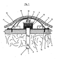
- the implanted, modular device consists of a catheter 1, which has a temperature sensor 2 and a pressure sensor 3 at its distal end and projects through the cranial bone 5 into the brain tissue 4.
- the base plate 6 fastened on the cranial bone 5 by means of screw 14 comprises an electronic unit and an integrated fastening element 7 with an internal thread.
- the screw 9 brings a force on the seal 8, whereby the space between the semi-flexible cover 12 and the base plate 6 is sealed against the brain tissue 4, while the catheter 1 is fixed to the base plate 6 and thus the skull bone 5 ,
- the micro-plug 10 located on the proximal end of the catheter 1 is connected to the electronic unit 11 via a line 16. Via a radio signal, the device is now tested for function. Subsequently, by means of the screws 15, the semi-flexible cover 12 tight, but releasably connected to the base plate 6. The scalp 13 straddles and protects the implanted device.
- the electronics unit 11 can use the body's own energies by using thermocouples or piezoelectronic devices or nanotubes in the CSF space.
Landscapes
- Health & Medical Sciences (AREA)
- Life Sciences & Earth Sciences (AREA)
- Surgery (AREA)
- Biophysics (AREA)
- Pathology (AREA)
- Engineering & Computer Science (AREA)
- Biomedical Technology (AREA)
- Heart & Thoracic Surgery (AREA)
- Medical Informatics (AREA)
- Molecular Biology (AREA)
- Physics & Mathematics (AREA)
- Animal Behavior & Ethology (AREA)
- General Health & Medical Sciences (AREA)
- Public Health (AREA)
- Veterinary Medicine (AREA)
- Neurosurgery (AREA)
- Hematology (AREA)
- Measuring And Recording Apparatus For Diagnosis (AREA)
- Apparatus For Radiation Diagnosis (AREA)
- Measurement And Recording Of Electrical Phenomena And Electrical Characteristics Of The Living Body (AREA)
- External Artificial Organs (AREA)
- Magnetic Resonance Imaging Apparatus (AREA)
Description
- Es ist bekannter Stand der Technik für die Messung des Hirndruckes, wie anderer Parameter im Hirn des Menschen, Sonden epidural oder subdural zu implantieren.
Diese Sonden sind mit Messsensoren bestückt, die den Hirndruck erfassen, in elektrische Signale umwandeln und über eine Kabelverbindung an einen Patientenmonitor leiten.
Dort werden die Messwerte verarbeitet und in Form von Zahlenwerten und grafisch als Kurven dargestellt.
Die Kabelverbindungen zwischen Sonden mit Messsensoren und den Patientenmonitoren sind jedoch nur sehr aufwändig herzustellen, da die Patientenmonitore verschieden gestaltete Steckerbuchsen aufweisen und fehleranfällig in der Handhabung sind. Zudem erfordert fast jedes Diagnosemesselement ein spezielles Kabel, so dass vor allem auf der Intensivstation Patienten mit einer unübersichtlichen Menge an Kabeln verbunden sind, was zu Komplikationen in der Pflege führt und ein Risiko für den Patienten darstellt.
Dies trifft besonders dann zu, wenn der Patient in Stresssituationen behandelt werden muss oder transportiert wird.
Fehlmessungen oder der Totalausfall der Messsonden sind unter Umständen möglich, mit der Konsequenz, nochmals neue Messsonden implantieren zu müssen.
Insgesamt ist also die Verwendung von Kabelverbindungen teuer und im Einzelfall mit hohen Risiken für den Patienten verbunden.
Derartige Sonden mit integrierten Messsensoren zur Implantation stellen beispielsweise die Firmen REHAU AG + Co, Johnson & Johnson, Camino, Medtronic her. - Die
WO-A-02/07596 - Gegenstand der
DE 43 29 898 A1 ist ein kabelloses, medizinisches Diagnose- und Überwachungsgerät, beispielsweise auch für Neuromonitoring. Die Vorrichtung umfasst eine Auswertestation und eine oder mehrere, an der Hautoberfläche des Patienten angebrachte, Elektroden.
Die Elektroden umfassen eine digitale Sendeeinheit mit Antenne, ggf. eine Empfangseinheit, eine Energieversorgungseinheit sowie mindestens einen Halbleitersensor. Die Halbleitersensoren können u. a. zur Detektion von EEG- oder EKG-Signalen verwendet werden.
Nachteilig an dieser Lösung ist, dass ausschließlich Elektroden verwendet werden können, welche an der Hautoberfläche des Patienten angebracht sind. - Der Versuch in Shunt-Systemen zur Behandlung von Hydrocephali Hirndruckmessungen dauerhaft oder ambulant zu realisieren, führte zur Kombination von implantierten Messsonden mit Sensoren, deren Messsignale telemetrisch mit der jeweiligen Auswerteeinheit verbunden sind.
Beispielsweise beschreibtDE 197 05 474 A1 eine implantierbare Messeinheit zur Messungen u. a. von Hirndrücken. Dabei sind Sensorelement und Telemetrieeinheit auf einer flexiblen Folie aufgebracht. Die Telemetrieeinheit hat eine äußere Spule, über welche die implantierte Schaltung induktiv mit Energie versorgt wird, außerdem werden dabei induktiv die im Senderelement gemessenen Daten an die Auswerteeinheit übertragen.
Nachteilig ist, dass eine solche induktive, kabellose Übertragung von Daten oder Energie nur über eine sehr kurze Distanz - einige Millimeter - funktioniert, also nur epidurale, evtl. auch subdurale Messungen möglich sind. In derDE 43 41 903 A1 wird eine besonders kleine, implantierbare Vorrichtung beschrieben, deren Außenabmessungen kleiner 1,0 x 1,5 x 0,6 mm sind und die zur kontinuierlichen Messung des Druckes und/oder des Durchflusses und/oder der Temperatur in Körpern oder Organen von Menschen oder Tieren geeignet ist. Diese Vorrichtung übermittelt Netzwerte bzw. Messsignale ohne Verkabelung perkutan an einen außerhalb des Körpers befindlichen Empfänger, welcher die Messsignale verarbeitet und zur Anzeige bringt.
Solche auf einem Chip integrierten, also fest gekoppelten Systeme Sensor - Telemetrieeinheit sind nicht geeignet, die gewünschten Parameter (beispielsweise Himdruck, Temperatur) an den für die Indikationsstellung optimalen Orten zu messen.
Problemlos lassen sie sich nämlich ausschließlich epidural, evtl. auch subdural, implantieren. Ihre Implantation in die für die Messungen wesentlich günstigeren Orte, nämlich in das Parenchym oder die Ventrikel, ist nicht möglich. - In diesen Bereichen ist auch die externe Energieversorgung durch Induktion oder HF-Felder kaum noch möglich, damit ist die Funktion der Mess- und Sendeeinheit nur für kurze Zeit gegeben.
Weiterhin führt der oft nötige, zusätzliche Einsatz bildgebender Verfahren, wie die Magnetresonanz, zur Funktionsstörung der implantierten Steuer- und Regelungstechnik bzw zu induktiven Strömen im Schaltungssystem, sowie nicht zuletzt zur Erwärmung und Schädigung des die Implantate umgebenden Gewebes. - Generell ist zum beschriebenen Stand der Technik bei der telemetrischen Übertragung von Signalen aus implantierten Sensoren zu sagen, dass bisher keine Berichte über deren erfolgreiche, praktische Umsetzung vorliegen.
- Da für die korrekte Erfassung von physiologischen Daten im menschlichen Hirn neben der Auslegung der sensitiven und spezifischen Sensoren vor allem die Messorte entscheidend sind, stellte sich daher die Aufgabe der vorliegenden Erfindung, eine Vorrichtung zur Messung von Parametern im Hirn bereitzustellen, die über folgende Eigenschaften verfügt:
- Die Messung der gewünschten Parameter ist an den üblichen = klassischen, medizinisch anerkannten Stellen, nämlich im Parenchym und/oder in den Ventrikeln möglich; bei Bedarf sollten auch weiterhin die epiduralen oder subduralen Messungen möglich sein.
- Die Übertragung und Aufbereitung der Patientendaten erfolgt digital und via Telemetrie.
- Es steht ein Baukastensystem zur Verfügung, mit dem die Messvorrichtung - je nach Anforderung - maßgeschneidert zusammengestellt werden kann.
- Die Elektronik-Einheit ist nach ihrer Sterilisation wieder verwendbar.
- Die Aufgabe konnte erfindungsgemäß dadurch gelöst werden, dass
- - die Sensoren in einem Katheter aus polymeren Werkstoffen angeordnet sind, der ggf. mindestens über ein Lumen zur Liquordrainage verfügt
- - die Elektronikeinheit in einer abgeschlossenen, vorzugsweise ringförmig angeordneten Baugruppe aufgenommen ist
- - der Katheter in der mittigen Ausnehmung der Grundplatte über ein ringförmiges Befestigungselement fest und dicht, jedoch lösbar fixiert ist
- - Sensoreinheit und Elektronikeinheit über einen Mikrostrecker verbunden sind
- - die Messeinheit mit Katheter und Sensor, der auf der Grundplatte montierten Elektronikeinheit mit der Energieversorgung und darüber eine wieder lösbare Abdeckung, komplett unter der Kopfhaut auf dem Schädelknochen platziert und nach außen vollständig abgeschlossen ist.
- Die Grundplatte ist semiflexibel, sie verfügt über eine mittige Ausnehmung mit Stutzen und integriertem, ringförmigem Befestigungselement. Alternativ kann auch an dessen Stelle ein Kugelgehäuse mit Ventil vorgesehen werden, das für Katheter mit wenigstens zwei verschiedenen Größen geeignet ist und das auch den Schrägsitz des Katheters in der Grundplatte ermöglicht.
Die Grundplatte wird nach ihrer Komplettierung mit der Elektronikeinheit und dem Katheter zur Implantation mit einer flexiblen, dichten und wieder lösbaren Abdeckung versehen. - Die Sensoreinheit besteht aus einem Katheter mit einem oder mehreren Sensoren zur Messung beispielsweise von Hirndruck, Temperatur, CO2-Sättigung oder pH-Wert usw. Zur Liquordrainage kann auch mindestens ein Lumen im Katheter integriert sein. Der Katheter verfügt am proximalen Ende über einen Mikrostecker, der den Kontakt zur Elektronikeinheit herstellt, so dass die Messsignale erfasst und an die Auswerteeinheit weitergegeben werden können.
- Die unter der semiflexiblen Abdeckung angeordnete Elektronikeinheit ist nach der Demontage von der Grundplatte und der Abkopplung des Katheters durch Lösen des Mikrosteckers resterilisierbar und damit wieder verwendbar.
- Besonders vorteilhaft an der erfindungsgemäßen Vorrichtung ist, dass auf Grund des modularen Aufbaus die Teilelemente je nach der aktuellen Anwendung zusammengestellt werden können. So lässt sich beispielsweise für die Messung im Parenchym ein kurzer Katheter mit einem Durchmesser von 3 CH, für Messungen im Ventrikelbereich mit Liquordrainage ein kurzer Katheter mit einem Durchmesser von 6 CH einsetzen.
- Erfindungsgemäß ist weiterhin besonders vorteilhaft, dass Sensoreinheit und Elektronikeinheit zunächst voneinander getrennt sind. Daher lässt sich der den Sensor / die Sensoren enthaltende Katheter auf übliche Weise, beispielsweise - nach Öffnung der Kopfhaut und Setzen eines Bohrlochs im Schädelknochen - über Hülse und Mandrin minimalinvasiv an den optimalen Messorten, nämlich den Ventrikeln oder dem Parenchym, platzieren.
Anschließend wird das proximale Ende des Katheters mit der mittigen Ausnehmung der Grundplatte über das Befestigungselement dicht verschraubt und mit der Elektronikeinheit über den Mikrostecker verbunden. Schließlich wird die so komplettierte Grundplatte mit einer semiflexiblen Abdeckung dicht verbunden und die Kopfhaut wieder geschlossen. - Die Einbettung des Sensors und der Verbindungsleitung in einen Katheter und in ein nicht metallisches Sensorgehäuse verhindert die Erwärmung des umliegenden Gewebes sowie die Dislokation am Messort und damit das Auftreten von Artefakten bei der Messung und der Anwendung der bildgebenden Diagnostik, insbesondere in der magnetischen Resonanztomografie (MRT).
Im Falle der Verwendung von Akkus ist so eine induktive, thermoelektrische oder HF-Feld-Aufladung gewährleistet. Deren Funktion kann durch eine Abschirmung der Bauteile oder durch das Abschalten der Sensoreinheit während der MRT-Untersuchung geschützt werden. - Im Falle von Kathetern, die über Messsensoren und ein Lumen zur Liquorableitung verfügen, ist auf der Grundplatte ein Verbindungsstutzen integriert, der das Lumen aus der Messeinheit patientennah ableitet und an einen Katheter, der in den Brust- oder Bauchraum des Patienten führt, ankoppelt. Möglich ist auch die Verbindung zu einem Shuntventil.
Jeder Systemaufbau lässt sich daher grundsätzlich als geschlossenes System gestalten. - Eine interessante, erfindungsgemäße Möglichkeit zur Energieversorgung des implantierten Systems ist folgende:
- Wird der Hirndruck im Ventrikel gemessen, lässt sich der Liquorfluss zur Energiegewinnung mittels eines miniaturisierten Dynamos heranziehen. Dabei ist im Sensorgehäuse eine Kammer mit Ein- und Ausströmöffnung integriert, zwischen denen eine Turbine mit angeschlossenem Dynamo montiert ist.
- In einem Ausführungsbeispiel soll nun die Erfindung im Detail erläutert werden; ergänzend dazu siehe die zeichnerische Erläuterung in
Fig. 1 . - Die implantierte, modular aufgebaute Vorrichtung besteht aus einem Katheter 1, der an seinem distalen Ende über einen Temperatursensor 2 und einen Drucksensor 3 verfügt und durch den Schädelknochen 5 ins Hirngewebe 4 hineinragt.
Die auf dem Schädelknochen 5 mittels Schraube 14 befestigte Grundplatte 6 umfasst eine Elektronikeinheit und ein integriertes Befestigungselement 7 mit innenliegendem Gewinde. Über dieses Gewinde bringt die Schraube 9 eine Kraft auf die Dichtung 8 auf, wodurch der Raum zwischen der semiflexiblen Abdeckung 12 und der Grundplatte 6 dicht gegenüber dem Hirngewebe 4 abgeschlossen ist, gleichzeitig der Katheter 1 auf der Grundplatte 6 und damit dem Schädelknochen 5 fixiert ist.
Der auf dem proximalen Ende des Katheters 1 befindliche Mikrostecker 10 ist über eine Leitung 16 mit der Elektronikeinheit 11 verbunden.
Über ein Funksignal wird nun die Vorrichtung auf Funktion geprüft. Anschließend wird mittels der Schrauben 15 die semiflexible Abdeckung 12 dicht, jedoch wieder lösbar, mit der Grundplatte 6 verbunden.
Die Kopfhaut 13 überspannt und schützt die implantierte Vorrichtung. - Die Elektronikeinheit 11 kann durch Verwendung von Thermoelementen oder piezoelektronischen Vorrichtungen oder Nanoturbinen im Liquorraum körpereigene Energien nutzen.
Claims (8)
- Vorrichtung zur Messung von Hirnparametern- mit einer Sensoreinheit (1-3), die derart ausgeführt ist, dass siedadurch gekennzeichnet, dass-- distal minimalinvasiv im Parenchym und/oder den Ventrikeln implantierbar ist,-- proximal in einem auf einer Grundplatte (6) zentriert angeordneten Befestigungselement (7) aufgenommen ist,- die Sensoreinheit (1-3) mit einer Elektronikeinheit (11) über einen Mikrostecker (10) elektrisch leitend verbunden ist,- die Messvorrichtung eine proximale Baugruppe aufweist, umfassend:-- das Befestigungselement (7),-- die im Befestigungselement (7) aufgenommenen Abschnitte der Sensoreinheit (1-3),-- die Elektronikeinheit (11),-- den Mikrostecker (10),- wobei die proximale Baugruppe (1-3, 7, 10, 11) derart ausgeführt ist, dass sie mittels einer semiflexiblen Abdeckung (12) fest und dicht, jedoch wieder lösbar, angeschlossen und zwischen Schädelknochen und Kopfhaut positionierbar ist.
- Vorrichtung nach Anspruch 1, dadurch gekennzeichnet, dass das Gesamtsystem modular aufgebaut ist.
- Vorrichtung nach Anspruch 1, dadurch gekennzeichnet, dass die Elektronikeinheit (11) aus den Hauptkomponenten Energieversorgung, Sender, Empfänger, Steuereinheit und Mikrosteckerbuchse zusammengesetzt ist.
- Vorrichtung nach Anspruch 1, dadurch gekennzeichnet, dass die Sensoreinheit umfasst einen Katheter (1) aus polymerem Werkstoff, sowie einen oder mehreren Sensoren (2, 3) zur Messung von Hirndruck und/oder Temperatur und/oder CO2-Partialdruck und/oder Sauerstoffpartialdruck.
- Vorrichtung nach Anspruch 4, dadurch gekennzeichnet, dass der Katheter (1) mindestens ein Lumen für die Sensorik, ggf. zusätzlich mindestens ein Lumen für die Liquordrainage enthält.
- Vorrichtung nach einem der Ansprüche 1 oder 5, dadurch gekennzeichnet, dass der ein Lumen für die Liquordrainage enthaltende Katheter (1) über einen Stutzen der Grundplatte (6) an einen weiteren, im Bauchraum des Patienten verlegten Katheter angeschlossen wird und mit diesem ein geschlossenes System bildet.
- Vorrichtung nach einem der Ansprüche 1 oder 3, dadurch gekennzeichnet, dass die Elektronikeinheit (11) sterilisierbar und wieder verwendbar ist.
- Vorrichtung nach den Ansprüchen 1, 3, oder 7, dadurch gekennzeichnet, dass die Elektronikeinheit (11) körpereigene Energien nutzt durch Verwendung von Thermoelementen oder piezoelektronischen Vorrichtungen oder Nanoturbinen im Liquorraum.
Applications Claiming Priority (3)
| Application Number | Priority Date | Filing Date | Title |
|---|---|---|---|
| DE10239743A DE10239743A1 (de) | 2002-08-29 | 2002-08-29 | Vorrichtung zur Messung von Parametern im Hirn |
| DE10239743 | 2002-08-29 | ||
| PCT/EP2003/009411 WO2004023993A1 (de) | 2002-08-29 | 2003-08-26 | Vorrichtung zur messung von parametern im hirn |
Publications (2)
| Publication Number | Publication Date |
|---|---|
| EP1531723A1 EP1531723A1 (de) | 2005-05-25 |
| EP1531723B1 true EP1531723B1 (de) | 2009-04-08 |
Family
ID=31895605
Family Applications (1)
| Application Number | Title | Priority Date | Filing Date |
|---|---|---|---|
| EP03794936A Expired - Lifetime EP1531723B1 (de) | 2002-08-29 | 2003-08-26 | Vorrichtung zur messung von parametern im hirn |
Country Status (10)
| Country | Link |
|---|---|
| US (1) | US20060025704A1 (de) |
| EP (1) | EP1531723B1 (de) |
| JP (1) | JP4344694B2 (de) |
| AT (1) | ATE427696T1 (de) |
| CA (1) | CA2496999A1 (de) |
| DE (2) | DE10239743A1 (de) |
| DK (1) | DK1531723T3 (de) |
| ES (1) | ES2322581T3 (de) |
| PT (1) | PT1531723E (de) |
| WO (1) | WO2004023993A1 (de) |
Cited By (1)
| Publication number | Priority date | Publication date | Assignee | Title |
|---|---|---|---|---|
| DE102012221284A1 (de) | 2012-11-21 | 2014-05-22 | Raumedic Ag | Medizinische Drucksensoreinrichtung sowie Set aus einer derartigen Drucksensoreinrichtung und mindestens einem Wechsel-Katheter |
Families Citing this family (26)
| Publication number | Priority date | Publication date | Assignee | Title |
|---|---|---|---|---|
| CA2539261C (en) | 2003-09-16 | 2011-05-17 | Cardiomems, Inc. | Implantable wireless sensor |
| US8026729B2 (en) | 2003-09-16 | 2011-09-27 | Cardiomems, Inc. | System and apparatus for in-vivo assessment of relative position of an implant |
| US7245117B1 (en) * | 2004-11-01 | 2007-07-17 | Cardiomems, Inc. | Communicating with implanted wireless sensor |
| US20060287602A1 (en) * | 2005-06-21 | 2006-12-21 | Cardiomems, Inc. | Implantable wireless sensor for in vivo pressure measurement |
| US8870787B2 (en) * | 2003-09-16 | 2014-10-28 | Cardiomems, Inc. | Ventricular shunt system and method |
| US7850676B2 (en) * | 2004-04-19 | 2010-12-14 | The Invention Science Fund I, Llc | System with a reservoir for perfusion management |
| DE102005008454B4 (de) * | 2005-02-24 | 2014-11-13 | Raumedic Ag | Anordnung mit Vorrichtung zur Messung von Hirnparametern |
| DE102005008627A1 (de) | 2005-02-25 | 2006-08-31 | Raumedic Ag | Sensorsystem zur Messung, Übertragung, Verarbeitung und Darstellung von physiologischen Parametern |
| DE102005024578A1 (de) * | 2005-05-25 | 2006-11-30 | Raumedic Ag | Sonde zur Messung des Sauerstoffgehaltes in biologischem Gewebe sowie Katheter mit einer derartigen Sonde |
| AU2006200951B2 (en) † | 2005-03-13 | 2012-01-19 | Integra LifeSciences Switzerland Sarl | Pressure sensing devices |
| EP1893080A2 (de) * | 2005-06-21 | 2008-03-05 | CardioMems, Inc. | Verfahren zur herstellung eines implantierbaren drahtlosen sensors für in-vivo-druckmessung |
| US20080275395A1 (en) * | 2006-12-22 | 2008-11-06 | Innerspace Medical, Inc. | MRI-Compatible Temperature-Sensing Catheter |
| US20090005701A1 (en) * | 2007-06-29 | 2009-01-01 | Codman & Shurtleff, Inc. | Cradled Sensor Assembly |
| DE102007046694A1 (de) | 2007-09-28 | 2009-04-09 | Raumedic Ag | Sensorsystem zur Messung, Übertragung, Verarbeitung und Darstellung eines Hirnparameters |
| DE102008011601A1 (de) * | 2008-02-28 | 2009-09-03 | Raumedic Ag | Patientendaten-Sensorvorrichtung |
| JP2012507332A (ja) | 2008-11-05 | 2012-03-29 | コーニンクレッカ フィリップス エレクトロニクス エヌ ヴィ | 頭蓋移植に関するデバイス及びシステム及びこれらの使用 |
| US10675451B2 (en) | 2010-10-22 | 2020-06-09 | Christoph Miethke Gmbh & Co Kg | Hydrocephalus shunt arrangement and components thereof for draining cerebrospinal fluid in a patient having hydrocephalus |
| US9901268B2 (en) | 2011-04-13 | 2018-02-27 | Branchpoint Technologies, Inc. | Sensor, circuitry, and method for wireless intracranial pressure monitoring |
| US12419564B2 (en) * | 2012-11-15 | 2025-09-23 | Flint Hills Scientific, L.L.C. | Sensor systems implantable at bones of the face or the skull base |
| US9409327B2 (en) * | 2013-03-09 | 2016-08-09 | Ctb, Inc. | Grain bin sensor cable forming method |
| US9848789B2 (en) | 2014-04-17 | 2017-12-26 | Branchpoint Technologies, Inc. | Wireless intracranial monitoring system |
| US9901269B2 (en) | 2014-04-17 | 2018-02-27 | Branchpoint Technologies, Inc. | Wireless intracranial monitoring system |
| CN104207768B (zh) * | 2014-08-25 | 2016-04-27 | 翟艳萍 | 神经疾病监测器 |
| EP3316212A1 (de) * | 2016-10-28 | 2018-05-02 | Thomson Licensing | Verfahren zum schärfen eines videos, zugehörige vorrichtung und computerprogrammprodukt |
| US11957442B2 (en) | 2019-10-03 | 2024-04-16 | Biosense Webster (Israel) Ltd. | Cerebrospinal-fluid-pressure-measuring device |
| AU2020256469B2 (en) | 2019-10-24 | 2026-03-05 | Longeviti Neuro Solutions, Inc | Cerebral spinal fluid shunt plug |
Family Cites Families (9)
| Publication number | Priority date | Publication date | Assignee | Title |
|---|---|---|---|---|
| US4127110A (en) * | 1976-05-24 | 1978-11-28 | Huntington Institute Of Applied Medical Research | Implantable pressure transducer |
| US4281667A (en) * | 1976-06-21 | 1981-08-04 | Cosman Eric R | Single diaphragm telemetric differential pressure sensing system |
| US4186749A (en) * | 1977-05-12 | 1980-02-05 | The United States Of America As Represented By The Administrator Of The National Aeronautics And Space Administration | Induction powered biological radiosonde |
| DE3135511C2 (de) * | 1981-09-08 | 1986-03-20 | Fraunhofer-Gesellschaft zur Förderung der angewandten Forschung e.V., 8000 München | Drucksensor, bestehend aus einem zylindrischen Topfkreis mit als Membran ausgebildeter Stirnfläche |
| US4519401A (en) * | 1983-09-20 | 1985-05-28 | Case Western Reserve University | Pressure telemetry implant |
| US6731976B2 (en) * | 1997-09-03 | 2004-05-04 | Medtronic, Inc. | Device and method to measure and communicate body parameters |
| US5957912A (en) * | 1998-04-16 | 1999-09-28 | Camino Neurocare, Inc. | Catheter having distal stylet opening and connector |
| WO2002007596A1 (en) * | 2000-07-21 | 2002-01-31 | Medtronic, Inc. | Measurement and communication of body parameters |
| EP1349492A2 (de) * | 2001-01-04 | 2003-10-08 | Medtronic, Inc. | Implantierbare medizinische vorrichtung mit einem sensor |
-
2002
- 2002-08-29 DE DE10239743A patent/DE10239743A1/de not_active Withdrawn
-
2003
- 2003-08-26 CA CA002496999A patent/CA2496999A1/en not_active Abandoned
- 2003-08-26 ES ES03794936T patent/ES2322581T3/es not_active Expired - Lifetime
- 2003-08-26 JP JP2004535158A patent/JP4344694B2/ja not_active Expired - Fee Related
- 2003-08-26 DK DK03794936T patent/DK1531723T3/da active
- 2003-08-26 US US10/526,071 patent/US20060025704A1/en not_active Abandoned
- 2003-08-26 EP EP03794936A patent/EP1531723B1/de not_active Expired - Lifetime
- 2003-08-26 WO PCT/EP2003/009411 patent/WO2004023993A1/de not_active Ceased
- 2003-08-26 PT PT03794936T patent/PT1531723E/pt unknown
- 2003-08-26 DE DE50311394T patent/DE50311394D1/de not_active Expired - Lifetime
- 2003-08-26 AT AT03794936T patent/ATE427696T1/de active
Cited By (2)
| Publication number | Priority date | Publication date | Assignee | Title |
|---|---|---|---|---|
| DE102012221284A1 (de) | 2012-11-21 | 2014-05-22 | Raumedic Ag | Medizinische Drucksensoreinrichtung sowie Set aus einer derartigen Drucksensoreinrichtung und mindestens einem Wechsel-Katheter |
| EP2735267A1 (de) | 2012-11-21 | 2014-05-28 | Raumedic Ag | Set aus einer medizinischen Drucksensoreinrichtung mit mindestens einem Wechsel-Katheter |
Also Published As
| Publication number | Publication date |
|---|---|
| JP2005537111A (ja) | 2005-12-08 |
| PT1531723E (pt) | 2009-05-18 |
| JP4344694B2 (ja) | 2009-10-14 |
| WO2004023993A1 (de) | 2004-03-25 |
| DK1531723T3 (da) | 2009-06-29 |
| ES2322581T3 (es) | 2009-06-23 |
| DE10239743A1 (de) | 2004-03-25 |
| ATE427696T1 (de) | 2009-04-15 |
| DE50311394D1 (de) | 2009-05-20 |
| AU2003264102A1 (en) | 2004-04-30 |
| CA2496999A1 (en) | 2004-03-25 |
| US20060025704A1 (en) | 2006-02-02 |
| EP1531723A1 (de) | 2005-05-25 |
Similar Documents
| Publication | Publication Date | Title |
|---|---|---|
| EP1531723A1 (de) | Vorrichtung zur messung von parametern im hirn | |
| EP2130566B1 (de) | Langgestrecktes Implantat mit externer Energieeinkopplung | |
| DE60219905T2 (de) | System und verfahren zum feststellen der loslösung einer implantiebaren medizinischen vorrichtung | |
| JP4912304B2 (ja) | 埋め込み可能なmri適合刺激リード及びアンテナ並びに関連するシステム | |
| US5246008A (en) | Method for monitoring a patient for rejection reactions to an implanted heart | |
| EP1707109B1 (de) | Datenübertragungssystem in Verbindung mit einem Implantat | |
| US20200170542A1 (en) | Systems and methods for positioning an intracranial device using brain activity | |
| US20090105557A1 (en) | System having wireless implantable sensor | |
| US20090105784A1 (en) | Miniature wireless system for deep brain stimulation | |
| DE112012003687T5 (de) | Medizinprodukt mit einem Funktionselement zum invasiven Einsatz im Körper eines Patienten | |
| EP2341978B1 (de) | Vorrichtung und system zur kranialen implantation | |
| DE102007038801A1 (de) | Implantierbare Druckmesseinrichtung und Anordnung zur Innendruckmessung in einem Blutgefäß | |
| DE10321099A1 (de) | Vorrichtung zur Druckmessung | |
| WO2006117154A1 (de) | Vorrichtung zur erfassung physiologischer messgrössen im körperinnren | |
| WO2010034546A1 (de) | Sensormodul zur erfassung von physiologischen daten | |
| DE29909923U1 (de) | Intravasal impantierbare Kapsel mit Halteapparat für ein miniaturisiertes Meßsystem zur telemetrischen Erfassung medizinischer Kenngrößen | |
| EP2364643B1 (de) | Elektromedizinisches Implantat und Überwachungssystem mit dem elektromedizinischen Implantat | |
| US8934973B2 (en) | Hub for implantable medical leads | |
| DE102004025797B3 (de) | Patientenpflegeeinheit mit einer Liegefläche | |
| WO2015032677A1 (de) | Katheter | |
| DE19705474A1 (de) | Implantierbare Meßeinheit zur intrakorporalen Messung von Patientendaten, insbesondere von Hirndrücken, für den mobilen Einsatz unter Alltagsbedingungen | |
| DE102007046169A1 (de) | Endorektalspule für Kernspintomographen | |
| US20060200065A1 (en) | MR-compatible fluid valve | |
| DE10009591B4 (de) | Messvorrichtung zur Überwachung von Körperfunktionsparametern | |
| US11439316B1 (en) | Implantable resonator system for deep-tissue EPR oximetry with reduced noise |
Legal Events
| Date | Code | Title | Description |
|---|---|---|---|
| PUAI | Public reference made under article 153(3) epc to a published international application that has entered the european phase |
Free format text: ORIGINAL CODE: 0009012 |
|
| 17P | Request for examination filed |
Effective date: 20050302 |
|
| AK | Designated contracting states |
Kind code of ref document: A1 Designated state(s): AT BE BG CH CY CZ DE DK EE ES FI FR GB GR HU IE IT LI LU MC NL PT RO SE SI SK TR |
|
| AX | Request for extension of the european patent |
Extension state: AL LT LV MK |
|
| DAX | Request for extension of the european patent (deleted) | ||
| RIN1 | Information on inventor provided before grant (corrected) |
Inventor name: GROPP, FRIEDRICH Inventor name: KUNZE, GERD Inventor name: STENDEL, RUEDIGER Inventor name: GOEHLER, KARLHEINZ |
|
| 17Q | First examination report despatched |
Effective date: 20080912 |
|
| GRAP | Despatch of communication of intention to grant a patent |
Free format text: ORIGINAL CODE: EPIDOSNIGR1 |
|
| GRAS | Grant fee paid |
Free format text: ORIGINAL CODE: EPIDOSNIGR3 |
|
| GRAA | (expected) grant |
Free format text: ORIGINAL CODE: 0009210 |
|
| AK | Designated contracting states |
Kind code of ref document: B1 Designated state(s): AT BE BG CH CY CZ DE DK EE ES FI FR GB GR HU IE IT LI LU MC NL PT RO SE SI SK TR |
|
| REG | Reference to a national code |
Ref country code: GB Ref legal event code: FG4D Free format text: NOT ENGLISH |
|
| REG | Reference to a national code |
Ref country code: CH Ref legal event code: EP |
|
| REG | Reference to a national code |
Ref country code: IE Ref legal event code: FG4D |
|
| REG | Reference to a national code |
Ref country code: PT Ref legal event code: SC4A Free format text: AVAILABILITY OF NATIONAL TRANSLATION Effective date: 20090512 |
|
| REF | Corresponds to: |
Ref document number: 50311394 Country of ref document: DE Date of ref document: 20090520 Kind code of ref document: P |
|
| REG | Reference to a national code |
Ref country code: ES Ref legal event code: FG2A Ref document number: 2322581 Country of ref document: ES Kind code of ref document: T3 |
|
| REG | Reference to a national code |
Ref country code: DK Ref legal event code: T3 |
|
| PG25 | Lapsed in a contracting state [announced via postgrant information from national office to epo] |
Ref country code: SI Free format text: LAPSE BECAUSE OF FAILURE TO SUBMIT A TRANSLATION OF THE DESCRIPTION OR TO PAY THE FEE WITHIN THE PRESCRIBED TIME-LIMIT Effective date: 20090408 |
|
| PG25 | Lapsed in a contracting state [announced via postgrant information from national office to epo] |
Ref country code: FI Free format text: LAPSE BECAUSE OF FAILURE TO SUBMIT A TRANSLATION OF THE DESCRIPTION OR TO PAY THE FEE WITHIN THE PRESCRIBED TIME-LIMIT Effective date: 20090408 |
|
| PG25 | Lapsed in a contracting state [announced via postgrant information from national office to epo] |
Ref country code: RO Free format text: LAPSE BECAUSE OF FAILURE TO SUBMIT A TRANSLATION OF THE DESCRIPTION OR TO PAY THE FEE WITHIN THE PRESCRIBED TIME-LIMIT Effective date: 20090408 Ref country code: EE Free format text: LAPSE BECAUSE OF FAILURE TO SUBMIT A TRANSLATION OF THE DESCRIPTION OR TO PAY THE FEE WITHIN THE PRESCRIBED TIME-LIMIT Effective date: 20090408 |
|
| PLBE | No opposition filed within time limit |
Free format text: ORIGINAL CODE: 0009261 |
|
| STAA | Information on the status of an ep patent application or granted ep patent |
Free format text: STATUS: NO OPPOSITION FILED WITHIN TIME LIMIT |
|
| PG25 | Lapsed in a contracting state [announced via postgrant information from national office to epo] |
Ref country code: SK Free format text: LAPSE BECAUSE OF FAILURE TO SUBMIT A TRANSLATION OF THE DESCRIPTION OR TO PAY THE FEE WITHIN THE PRESCRIBED TIME-LIMIT Effective date: 20090408 |
|
| 26N | No opposition filed |
Effective date: 20100111 |
|
| PG25 | Lapsed in a contracting state [announced via postgrant information from national office to epo] |
Ref country code: BG Free format text: LAPSE BECAUSE OF FAILURE TO SUBMIT A TRANSLATION OF THE DESCRIPTION OR TO PAY THE FEE WITHIN THE PRESCRIBED TIME-LIMIT Effective date: 20090708 Ref country code: MC Free format text: LAPSE BECAUSE OF NON-PAYMENT OF DUE FEES Effective date: 20090831 |
|
| PG25 | Lapsed in a contracting state [announced via postgrant information from national office to epo] |
Ref country code: GR Free format text: LAPSE BECAUSE OF FAILURE TO SUBMIT A TRANSLATION OF THE DESCRIPTION OR TO PAY THE FEE WITHIN THE PRESCRIBED TIME-LIMIT Effective date: 20090709 |
|
| PGFP | Annual fee paid to national office [announced via postgrant information from national office to epo] |
Ref country code: IE Payment date: 20100820 Year of fee payment: 8 |
|
| PGFP | Annual fee paid to national office [announced via postgrant information from national office to epo] |
Ref country code: CZ Payment date: 20100816 Year of fee payment: 8 Ref country code: TR Payment date: 20100818 Year of fee payment: 8 |
|
| PGFP | Annual fee paid to national office [announced via postgrant information from national office to epo] |
Ref country code: PT Payment date: 20100812 Year of fee payment: 8 |
|
| PG25 | Lapsed in a contracting state [announced via postgrant information from national office to epo] |
Ref country code: LU Free format text: LAPSE BECAUSE OF NON-PAYMENT OF DUE FEES Effective date: 20090826 |
|
| PG25 | Lapsed in a contracting state [announced via postgrant information from national office to epo] |
Ref country code: HU Free format text: LAPSE BECAUSE OF FAILURE TO SUBMIT A TRANSLATION OF THE DESCRIPTION OR TO PAY THE FEE WITHIN THE PRESCRIBED TIME-LIMIT Effective date: 20091009 |
|
| PG25 | Lapsed in a contracting state [announced via postgrant information from national office to epo] |
Ref country code: CY Free format text: LAPSE BECAUSE OF FAILURE TO SUBMIT A TRANSLATION OF THE DESCRIPTION OR TO PAY THE FEE WITHIN THE PRESCRIBED TIME-LIMIT Effective date: 20090408 |
|
| PGFP | Annual fee paid to national office [announced via postgrant information from national office to epo] |
Ref country code: DK Payment date: 20110824 Year of fee payment: 9 |
|
| PGFP | Annual fee paid to national office [announced via postgrant information from national office to epo] |
Ref country code: SE Payment date: 20110823 Year of fee payment: 9 Ref country code: AT Payment date: 20110722 Year of fee payment: 9 |
|
| PGFP | Annual fee paid to national office [announced via postgrant information from national office to epo] |
Ref country code: BE Payment date: 20110822 Year of fee payment: 9 Ref country code: NL Payment date: 20110825 Year of fee payment: 9 |
|
| REG | Reference to a national code |
Ref country code: PT Ref legal event code: MM4A Free format text: LAPSE DUE TO NON-PAYMENT OF FEES Effective date: 20120227 |
|
| PG25 | Lapsed in a contracting state [announced via postgrant information from national office to epo] |
Ref country code: CZ Free format text: LAPSE BECAUSE OF NON-PAYMENT OF DUE FEES Effective date: 20110826 |
|
| REG | Reference to a national code |
Ref country code: IE Ref legal event code: MM4A |
|
| PG25 | Lapsed in a contracting state [announced via postgrant information from national office to epo] |
Ref country code: PT Free format text: LAPSE BECAUSE OF NON-PAYMENT OF DUE FEES Effective date: 20120227 |
|
| PG25 | Lapsed in a contracting state [announced via postgrant information from national office to epo] |
Ref country code: IE Free format text: LAPSE BECAUSE OF NON-PAYMENT OF DUE FEES Effective date: 20110826 |
|
| BERE | Be: lapsed |
Owner name: RAUMEDIC A.G. Effective date: 20120831 |
|
| REG | Reference to a national code |
Ref country code: NL Ref legal event code: V1 Effective date: 20130301 |
|
| REG | Reference to a national code |
Ref country code: DK Ref legal event code: EBP Ref country code: SE Ref legal event code: EUG |
|
| REG | Reference to a national code |
Ref country code: AT Ref legal event code: MM01 Ref document number: 427696 Country of ref document: AT Kind code of ref document: T Effective date: 20120826 |
|
| PG25 | Lapsed in a contracting state [announced via postgrant information from national office to epo] |
Ref country code: SE Free format text: LAPSE BECAUSE OF NON-PAYMENT OF DUE FEES Effective date: 20120827 Ref country code: NL Free format text: LAPSE BECAUSE OF NON-PAYMENT OF DUE FEES Effective date: 20130301 |
|
| PG25 | Lapsed in a contracting state [announced via postgrant information from national office to epo] |
Ref country code: BE Free format text: LAPSE BECAUSE OF NON-PAYMENT OF DUE FEES Effective date: 20120831 |
|
| PG25 | Lapsed in a contracting state [announced via postgrant information from national office to epo] |
Ref country code: AT Free format text: LAPSE BECAUSE OF NON-PAYMENT OF DUE FEES Effective date: 20120826 |
|
| PG25 | Lapsed in a contracting state [announced via postgrant information from national office to epo] |
Ref country code: DK Free format text: LAPSE BECAUSE OF NON-PAYMENT OF DUE FEES Effective date: 20120831 |
|
| PG25 | Lapsed in a contracting state [announced via postgrant information from national office to epo] |
Ref country code: TR Free format text: LAPSE BECAUSE OF NON-PAYMENT OF DUE FEES Effective date: 20110826 |
|
| REG | Reference to a national code |
Ref country code: FR Ref legal event code: PLFP Year of fee payment: 14 |
|
| REG | Reference to a national code |
Ref country code: FR Ref legal event code: PLFP Year of fee payment: 15 |
|
| REG | Reference to a national code |
Ref country code: FR Ref legal event code: PLFP Year of fee payment: 16 |
|
| PGFP | Annual fee paid to national office [announced via postgrant information from national office to epo] |
Ref country code: IT Payment date: 20200831 Year of fee payment: 18 Ref country code: CH Payment date: 20200722 Year of fee payment: 18 |
|
| PGFP | Annual fee paid to national office [announced via postgrant information from national office to epo] |
Ref country code: FR Payment date: 20210823 Year of fee payment: 19 |
|
| PGFP | Annual fee paid to national office [announced via postgrant information from national office to epo] |
Ref country code: GB Payment date: 20210824 Year of fee payment: 19 Ref country code: ES Payment date: 20210917 Year of fee payment: 19 |
|
| PGFP | Annual fee paid to national office [announced via postgrant information from national office to epo] |
Ref country code: DE Payment date: 20211026 Year of fee payment: 19 |
|
| REG | Reference to a national code |
Ref country code: CH Ref legal event code: PL |
|
| PG25 | Lapsed in a contracting state [announced via postgrant information from national office to epo] |
Ref country code: LI Free format text: LAPSE BECAUSE OF NON-PAYMENT OF DUE FEES Effective date: 20210831 Ref country code: CH Free format text: LAPSE BECAUSE OF NON-PAYMENT OF DUE FEES Effective date: 20210831 |
|
| PG25 | Lapsed in a contracting state [announced via postgrant information from national office to epo] |
Ref country code: IT Free format text: LAPSE BECAUSE OF NON-PAYMENT OF DUE FEES Effective date: 20210826 |
|
| REG | Reference to a national code |
Ref country code: DE Ref legal event code: R119 Ref document number: 50311394 Country of ref document: DE |
|
| GBPC | Gb: european patent ceased through non-payment of renewal fee |
Effective date: 20220826 |
|
| PG25 | Lapsed in a contracting state [announced via postgrant information from national office to epo] |
Ref country code: FR Free format text: LAPSE BECAUSE OF NON-PAYMENT OF DUE FEES Effective date: 20220831 Ref country code: DE Free format text: LAPSE BECAUSE OF NON-PAYMENT OF DUE FEES Effective date: 20230301 |
|
| REG | Reference to a national code |
Ref country code: ES Ref legal event code: FD2A Effective date: 20230929 |
|
| PG25 | Lapsed in a contracting state [announced via postgrant information from national office to epo] |
Ref country code: GB Free format text: LAPSE BECAUSE OF NON-PAYMENT OF DUE FEES Effective date: 20220826 Ref country code: ES Free format text: LAPSE BECAUSE OF NON-PAYMENT OF DUE FEES Effective date: 20220827 |