EP1531276A2 - Power transmission shaft - Google Patents
Power transmission shaft Download PDFInfo
- Publication number
- EP1531276A2 EP1531276A2 EP04256924A EP04256924A EP1531276A2 EP 1531276 A2 EP1531276 A2 EP 1531276A2 EP 04256924 A EP04256924 A EP 04256924A EP 04256924 A EP04256924 A EP 04256924A EP 1531276 A2 EP1531276 A2 EP 1531276A2
- Authority
- EP
- European Patent Office
- Prior art keywords
- serrated
- smooth
- torque transmission
- fatigue strength
- hardening
- Prior art date
- Legal status (The legal status is an assumption and is not a legal conclusion. Google has not performed a legal analysis and makes no representation as to the accuracy of the status listed.)
- Withdrawn
Links
Images


Classifications
-
- C—CHEMISTRY; METALLURGY
- C21—METALLURGY OF IRON
- C21D—MODIFYING THE PHYSICAL STRUCTURE OF FERROUS METALS; GENERAL DEVICES FOR HEAT TREATMENT OF FERROUS OR NON-FERROUS METALS OR ALLOYS; MAKING METAL MALLEABLE, e.g. BY DECARBURISATION OR TEMPERING
- C21D9/00—Heat treatment, e.g. annealing, hardening, quenching or tempering, adapted for particular articles; Furnaces therefor
- C21D9/28—Heat treatment, e.g. annealing, hardening, quenching or tempering, adapted for particular articles; Furnaces therefor for plain shafts
-
- F—MECHANICAL ENGINEERING; LIGHTING; HEATING; WEAPONS; BLASTING
- F16—ENGINEERING ELEMENTS AND UNITS; GENERAL MEASURES FOR PRODUCING AND MAINTAINING EFFECTIVE FUNCTIONING OF MACHINES OR INSTALLATIONS; THERMAL INSULATION IN GENERAL
- F16C—SHAFTS; FLEXIBLE SHAFTS; ELEMENTS OR CRANKSHAFT MECHANISMS; ROTARY BODIES OTHER THAN GEARING ELEMENTS; BEARINGS
- F16C3/00—Shafts; Axles; Cranks; Eccentrics
- F16C3/02—Shafts; Axles
-
- F—MECHANICAL ENGINEERING; LIGHTING; HEATING; WEAPONS; BLASTING
- F16—ENGINEERING ELEMENTS AND UNITS; GENERAL MEASURES FOR PRODUCING AND MAINTAINING EFFECTIVE FUNCTIONING OF MACHINES OR INSTALLATIONS; THERMAL INSULATION IN GENERAL
- F16D—COUPLINGS FOR TRANSMITTING ROTATION; CLUTCHES; BRAKES
- F16D3/00—Yielding couplings, i.e. with means permitting movement between the connected parts during the drive
- F16D3/16—Universal joints in which flexibility is produced by means of pivots or sliding or rolling connecting parts
- F16D3/20—Universal joints in which flexibility is produced by means of pivots or sliding or rolling connecting parts one coupling part entering a sleeve of the other coupling part and connected thereto by sliding or rolling members
-
- C—CHEMISTRY; METALLURGY
- C21—METALLURGY OF IRON
- C21D—MODIFYING THE PHYSICAL STRUCTURE OF FERROUS METALS; GENERAL DEVICES FOR HEAT TREATMENT OF FERROUS OR NON-FERROUS METALS OR ALLOYS; MAKING METAL MALLEABLE, e.g. BY DECARBURISATION OR TEMPERING
- C21D1/00—General methods or devices for heat treatment, e.g. annealing, hardening, quenching or tempering
- C21D1/06—Surface hardening
- C21D1/09—Surface hardening by direct application of electrical or wave energy; by particle radiation
- C21D1/10—Surface hardening by direct application of electrical or wave energy; by particle radiation by electric induction
-
- C—CHEMISTRY; METALLURGY
- C21—METALLURGY OF IRON
- C21D—MODIFYING THE PHYSICAL STRUCTURE OF FERROUS METALS; GENERAL DEVICES FOR HEAT TREATMENT OF FERROUS OR NON-FERROUS METALS OR ALLOYS; MAKING METAL MALLEABLE, e.g. BY DECARBURISATION OR TEMPERING
- C21D2221/00—Treating localised areas of an article
-
- C—CHEMISTRY; METALLURGY
- C21—METALLURGY OF IRON
- C21D—MODIFYING THE PHYSICAL STRUCTURE OF FERROUS METALS; GENERAL DEVICES FOR HEAT TREATMENT OF FERROUS OR NON-FERROUS METALS OR ALLOYS; MAKING METAL MALLEABLE, e.g. BY DECARBURISATION OR TEMPERING
- C21D7/00—Modifying the physical properties of iron or steel by deformation
- C21D7/02—Modifying the physical properties of iron or steel by deformation by cold working
- C21D7/04—Modifying the physical properties of iron or steel by deformation by cold working of the surface
- C21D7/06—Modifying the physical properties of iron or steel by deformation by cold working of the surface by shot-peening or the like
-
- F—MECHANICAL ENGINEERING; LIGHTING; HEATING; WEAPONS; BLASTING
- F16—ENGINEERING ELEMENTS AND UNITS; GENERAL MEASURES FOR PRODUCING AND MAINTAINING EFFECTIVE FUNCTIONING OF MACHINES OR INSTALLATIONS; THERMAL INSULATION IN GENERAL
- F16D—COUPLINGS FOR TRANSMITTING ROTATION; CLUTCHES; BRAKES
- F16D2300/00—Special features for couplings or clutches
- F16D2300/10—Surface characteristics; Details related to material surfaces
-
- Y—GENERAL TAGGING OF NEW TECHNOLOGICAL DEVELOPMENTS; GENERAL TAGGING OF CROSS-SECTIONAL TECHNOLOGIES SPANNING OVER SEVERAL SECTIONS OF THE IPC; TECHNICAL SUBJECTS COVERED BY FORMER USPC CROSS-REFERENCE ART COLLECTIONS [XRACs] AND DIGESTS
- Y02—TECHNOLOGIES OR APPLICATIONS FOR MITIGATION OR ADAPTATION AGAINST CLIMATE CHANGE
- Y02P—CLIMATE CHANGE MITIGATION TECHNOLOGIES IN THE PRODUCTION OR PROCESSING OF GOODS
- Y02P10/00—Technologies related to metal processing
- Y02P10/25—Process efficiency
-
- Y—GENERAL TAGGING OF NEW TECHNOLOGICAL DEVELOPMENTS; GENERAL TAGGING OF CROSS-SECTIONAL TECHNOLOGIES SPANNING OVER SEVERAL SECTIONS OF THE IPC; TECHNICAL SUBJECTS COVERED BY FORMER USPC CROSS-REFERENCE ART COLLECTIONS [XRACs] AND DIGESTS
- Y10—TECHNICAL SUBJECTS COVERED BY FORMER USPC
- Y10S—TECHNICAL SUBJECTS COVERED BY FORMER USPC CROSS-REFERENCE ART COLLECTIONS [XRACs] AND DIGESTS
- Y10S29/00—Metal working
- Y10S29/049—Work hardening with other step
Definitions
- the present invention relates to a power transmission shaft coupled to a constant velocity joint for torque transmission.
- a power transmission shaft combined with a constant velocity joint is employed in various mechanical parts of an automobile, an industrial machine and so on.
- Such kind of power transmission shaft is usually coupled with a mating member (boss) fitted around an outer circumference thereof via a serration or a spline, for transmitting a torque to the mating member.
- the serrated shaft or the spline shaft is made of a medium carbon steel or a low-alloy steel, subjected to a heat treatment such as a surface hardening treatment or a thermal refining, more specifically a induction hardening, carburized quenching, nitriding, etc. for increasing a shaft strength, taking into consideration the plastic workability, mechanical workability and cost.
- the Japanese patent publication No.3194093 discloses a technique for improving a shaft strength by a heat treatment, wherein a induction hardening and a carburized quenching is applied to a shaft-shaped mechanical part, so that a ratio of an effective depth of hardening against the part diameter is set in a range of 0.4 to 0.8.
- the heat treatment is applied to the part without particular distinction of a serrated portion for torque transmission such as a spline and a smooth portion on a cylindrical surface where such serration is not formed.
- a serrated portion for torque transmission such as a spline
- a smooth portion on a cylindrical surface where such serration is not formed This can be construed as a result of performing the heat treatment simultaneously and under a same condition, on both of the serrated portion for torque transmission and the smooth portion, in which case a depth of hardening becomes substantially the same in the serrated portion for torque transmission and the smooth portion.
- the present invention provides a power transmission shaft coupled to an inner joint member or an outer joint member of a constant velocity joint, and provided with a smooth portion having an outer circumferential surface of a cylindrical shape and a serrated portion for torque transmission having a cut-up portion at an end portion thereof, wherein the smooth portion and the serrated portion for torque transmission are respectively induction-hardened, and a hardening ratio of the smooth portion is set at a different value from that of the serrated portion for torque transmission, such that a fatigue strength of the smooth portion becomes equal to or greater than a fatigue strength of the serrated portion for torque transmission.
- the power transmission shaft herein referred to stands for a shaft member to be coupled to an inner joint member or an outer joint member of a constant velocity joint.
- the serrated portion for torque transmission is provided with notches for torque transmission formed along an axial direction and aligned in a circumferential direction, so as to transmit a torque to a mating member (boss) by getting engaged with notches of the mating member fitted on an outer circumference of the shaft, typically seen in a spline or a serration.
- the end portion of the serrated portion for torque transmission designates an end portion on the side of the other end of the shaft in the serrated portion formed on the one end of the shaft.
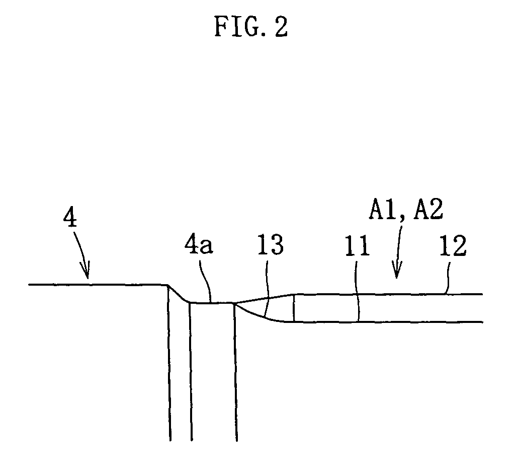
- cut-up portion means region that, in a serrated portion for torque transmission A1, A2 including a minor diameter portion 11 and a major diameter portion 12 as shown in Fig. 2, a diameter of the minor diameter portion 11 is expanded in a radial direction, so as to meet an outer circumferential surface 4a of the shaft 4 at the end portion of the serrated portion, where the minor diameter portion 11 and the major diameter portion 12 meet.
- Fig. 4 shows results of a fatigue test (fatigue test under completely reversed torsion) carried out by the present inventor for establishing a relation between a depth of hardening and a fatigue strength.
- the horizontal axis represents a hardening ratio (depth of hardening a/radius r), and the vertical axis represents a strength ratio with respect to a reference strength 1 corresponding to the hardening ratio of 0.35, based on a maximum shearing stress data obtained from repetitions of 300,000 times.
- Circular marks plotted in Fig. 4 represent data of a smooth portion, while square marks represent data of a serrated portion for torque transmission.
- the "depth of hardening" in the above formula is a value of a minor diameter portion of the serration
- the "radius" is that of a minor diameter portion.
- the strength ratio shows an upwardly protruding feature (shown by a solid line) with respect to the hardening ratio, with a peak of fatigue strength around the hardening ratio of 0.5 to 0.6, and the fatigue strength drops with both an increase or a decrease of the hardening ratio.
- an upwardly protruding feature shown by a dotted line
- an extent of decrease in the fatigue strength on both sides of the peak is milder than the case of the smooth portion.
- a fatigue strength depends on a depth of hardening more largely in the smooth portion than in the serrated portion for torque transmission. Also, upon comparing a fatigue strength of the smooth portion and of the serrated portion for torque transmission under a same hardening ratio, it has been proven that a fatigue strength of the serrated portion for torque transmission is superior to that of the smooth portion when the hardening ratio is low, while a fatigue strength of the smooth portion is superior to that of the serrated portion for torque transmission when the hardening ratio is high.
- a hardening ratio of the smooth portion is 0.40 or more, that a fatigue strength of the smooth portion exceeds a practically applicable value (strength ratio approx. 0.85).
- a hardening ratio of the smooth portion exceeds 0.70, a fatigue strength of the smooth portion drops below a permissible extent. Therefore, it is desirable to set a hardening ratio of the smooth portion to be 0.40 or more (more preferably, 0.45 or more), but 0.70 or less (more preferably 0.65 or less).
- a hardening ratio of the serrated portion for torque transmission is 0.20 or more (more preferably 0.30 or more), but 0.60 or less (more preferably 0.57 or less). It is because in case where a hardening ratio is below 0.20 a stable hardening effect cannot be achieved, while when a hardening ratio exceeds 0.60 a fatigue strength of the serrated portion for torque transmission drops significantly.
- a shot peening process to the serrated portion for torque transmission and the smooth portion increases a compression residual stress of a surface thereof, thereby further enhancing the fatigue strength.
- a fatigue strength can be improved over an entirety of a power transmission shaft.
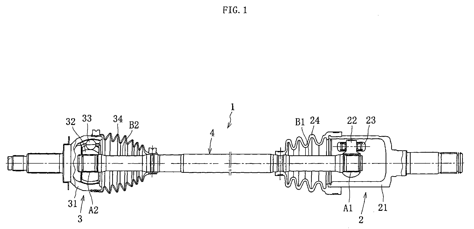
- Fig. 1 is a cross-sectional view showing a driveshaft for a vehicle such as an automobile, provided with a sliding type constant velocity joint 2 and a fixed type constant velocity joint 3 on the respective end portions thereof, via which the driveshaft 1 is connected to a driving system.
- a central side portion (inboard side) thereof in a widthwise direction of the vehicle is linked to a differential gear (not shown) via a tripod type constant velocity joint 2, while an outer portion (outboard side) in a widthwise direction of the vehicle is linked to an axle (not shown) via a Rzeppa type constant velocity joint 3.
- various types of constant velocity joint may be provided, without limitation to the constant velocity joint 2, 3 shown in Fig. 1.
- the constant velocity joint 2, 3 are basically constituted of cup-shaped outer joint member 21, 31, inner joint member 22, 32 disposed inside the outer joint member, and torque transmission member 23, 33 which transmit a torque between the outer joint member 21, 31 and the inner joint member 22, 32.
- rollers are employed as the torque transmission member 23, while balls are employed as the torque transmission member 33 of the Rzeppa type constant velocity joint on the outboard side.
- Respective end portions of a solid intermediate shaft 4 are serration-fitted along an inner circumferential surface of the inner joint member 22, 32, so that the torque transmission is performed via the serration-fitted portion between the constant velocity joint 2 and 3.
- the intermediate shaft 4 is provided with serrated portion A1, A2 on the respective end portions thereof, which serve as serrated portions for torque transmission.
- the serrated portion A1 on the inboard side is provided with a serration formed along an axial direction, and a diameter of and end portion of the minor diameter portion 11, out of the minor diameter portion 11 and the major diameter portion 12 of the serrated portion, is expanded in a direction that forms an arc shape cross-section, so as to meet an outer circumferential surface 4a of the shaft 4, as shown in Fig. 2.
- the expanded surface 13 (cut-up portion) of the end portion of the minor diameter portion 11 may be formed in a cylindrical shape, or a spherical shape.
- the serrated portion A2 on the outboard side is of the same configuration as the serrated portion A1 on the inboard side.
- the intermediate shaft 4 is provided with smooth portions having a cylindrical outer circumferential surface in a plurality of regions along an axial direction.
- the smooth portions B1, B2 having a smallest diameter are respectively located on end potions of the intermediate shaft 4, and inside boots 24, 34 of the constant velocity joint 2, 3.
- a diameter ratio of the smooth portions B1, B2 with respect to the respective adjacent serrated portions A1, A2 is set within a range of 0.95 to 1.05.
- a carbon steel for example an S40C to S45C medium carbon steel according to JIS is forged, and after plastic working of the serrated portions A1, A2 by cold rolling or cold press, an induction hardening applied to the overall driveshaft. It is desirable to perform the induction hardening twice to sufficiently apply a thermal effect to a core portion, to thereby form a dual phase structure of a ferrite and a martensite, though it is possible to form such dual phase structure in a core portion by a single hardening session when an appropriate measure is taken, for example using a relatively low frequency, prolong a heating time, prolong a cooling time after finishing the heating (delay time), etc.
- a hardening ratio of the smooth portion B1, B2 after the hardening is to be set such that a fatigue strength of the smooth portion B1 becomes not less than a fatigue strength of the adjacent serrated portion A1 as already described, taking into consideration the characteristic of the smooth portion that a fatigue strength largely varies depending on a difference of a depth of hardening (likewise, such that a fatigue strength of the smooth portion B2 becomes not less than that of the serrated portion A2).
- a hardening ratio of the smooth portions B1 and B2 at 0.40 or more (more preferably 0.45 or more), but 0.70 or less (more preferably 0.65 or less), and to set a hardening ratio of the serrated portions A1 and A2 at 0.20 or more (more preferably 0.30 or more), but 0.60 or less (more preferably 0.57 or less), as well as at a different hardening ratio between the smooth portion and the serrated portion.
- Different hardening ratios can be determined by adjusting a depth of hardening, for example changing a power to be input to an induction hardening apparatus by portions, or changing a heating time, etc.
- a fatigue strength of the smooth portions B1 and B2 is less variable depending on a hardening ratio, and stably stays in a high level. Therefore, setting a hardening ratio of the smooth portions B1, B2 so as to achieve a fatigue strength at least equal to or greater than that of the serrated portions A1, A2 permits achieving a high fatigue strength over an entirety of the intermediate shaft 4.
- the compression residual stress value may be achieved, for example by performing the shot peening twice.
- the shot peening may be applied to an entirety of the intermediate shaft 4, or alternatively to the serrated portions A1, A2 only, which are inferior in fatigue strength to the smooth portions B1, B2.
- the intermediate shaft 4 of the driveshaft 1 refers to the intermediate shaft 4 of the driveshaft 1 as an example of the power transmission shaft
- the scope of the present invention is not limited to the intermediate shaft 4, but is extensively applicable to a power transmission shaft that can be connected to the inner joint member 22, 32 or the outer joint member 21, 31 of the constant velocity joint 2, 3.
- Fig. 3 shows a stab shaft 40 (a press-fitted stab shaft or a welded stab shaft) as an example of the power transmission shaft, which is provided with a serrated portion A on an end portion thereof for connection to the inner joint member 22, 32 of the constant velocity joint 2, 3, and a flange portion 41 on the other end portion thereof for press-fitting or welding a steel pipe.
- a smooth portion B of a smallest diameter is located between the flange portion 41 and the serrated portion A. Setting a hardening ratio of the serrated portion A and the smooth portion B according to the foregoing relation permits achieving a similar advantage.
Landscapes
- Engineering & Computer Science (AREA)
- General Engineering & Computer Science (AREA)
- Chemical & Material Sciences (AREA)
- Mechanical Engineering (AREA)
- Ocean & Marine Engineering (AREA)
- Thermal Sciences (AREA)
- Physics & Mathematics (AREA)
- Crystallography & Structural Chemistry (AREA)
- Materials Engineering (AREA)
- Metallurgy (AREA)
- Organic Chemistry (AREA)
- Shafts, Cranks, Connecting Bars, And Related Bearings (AREA)
- Heat Treatment Of Articles (AREA)
Abstract
Description
Claims (4)
- A power transmission shaft coupled to an inner joint member or an outer joint member of a constant velocity joint, and provided with a smooth portion having an outer circumferential surface of a cylindrical shape and a serrated portion for torque transmission having a cut-up portion at an end portion thereof,
wherein said smooth portion and said serrated portion for torque transmission are respectively induction-hardened, and
a hardening ratio of said smooth portion is set at a different value from that of said serrated portion for torque transmission, such that a fatigue strength of said smooth portion becomes equal to or greater than a fatigue strength of said serrated portion for torque transmission. - The power transmission shaft according to Claim 1, wherein a hardening ratio of said smooth portion is not less than 0.40 but not more than 0.70.
- The power transmission shaft according to Claim 2, wherein a hardening ratio of said serrated portion for torque transmission is not less than 0.20 but not more than 0.60.
- The power transmission shaft according to Claim 1, 2 and 3 wherein a shot peening process is applied to said smooth portion and to said serrated portion for torque transmission.
Applications Claiming Priority (2)
| Application Number | Priority Date | Filing Date | Title |
|---|---|---|---|
| JP2003382831 | 2003-11-12 | ||
| JP2003382831A JP2005146313A (en) | 2003-11-12 | 2003-11-12 | Power transmission shaft |
Publications (2)
| Publication Number | Publication Date |
|---|---|
| EP1531276A2 true EP1531276A2 (en) | 2005-05-18 |
| EP1531276A3 EP1531276A3 (en) | 2006-02-01 |
Family
ID=34431451
Family Applications (1)
| Application Number | Title | Priority Date | Filing Date |
|---|---|---|---|
| EP04256924A Withdrawn EP1531276A3 (en) | 2003-11-12 | 2004-11-09 | Power transmission shaft |
Country Status (4)
| Country | Link |
|---|---|
| US (1) | US7399230B2 (en) |
| EP (1) | EP1531276A3 (en) |
| JP (1) | JP2005146313A (en) |
| CN (1) | CN1616838A (en) |
Families Citing this family (7)
| Publication number | Priority date | Publication date | Assignee | Title |
|---|---|---|---|---|
| JP2007177275A (en) * | 2005-12-27 | 2007-07-12 | Jfe Steel Kk | Power transmission shaft for constant velocity universal joint |
| WO2008032626A1 (en) * | 2006-09-11 | 2008-03-20 | Ntn Corporation | Power transmission spline |
| JP2008087003A (en) * | 2006-09-29 | 2008-04-17 | Toyota Motor Corp | Friction welding member |
| JP2011085152A (en) * | 2009-10-13 | 2011-04-28 | Ntn Corp | Power transmission shaft, and assembly |
| CN105114479A (en) * | 2015-09-14 | 2015-12-02 | 温州聚泉汽车部件有限公司 | Constant-velocity universal joint transmission shaft |
| US10385929B2 (en) * | 2016-01-06 | 2019-08-20 | Boninfante Friction, Inc. | Vehicle input shafts |
| JP6310489B2 (en) * | 2016-02-09 | 2018-04-11 | 本田技研工業株式会社 | Drive shaft and manufacturing method thereof |
Family Cites Families (5)
| Publication number | Priority date | Publication date | Assignee | Title |
|---|---|---|---|---|
| US3024626A (en) * | 1959-10-02 | 1962-03-13 | Eaton Mfg Co | Axle shaft |
| EP0507324A3 (en) * | 1991-04-05 | 1993-07-28 | Kanegafuchi Kagaku Kogyo Kabushiki Kaisha | Composite molding of resin-bonded magnet for machine parts and process for producing the same |
| WO2000005514A1 (en) | 1998-07-22 | 2000-02-03 | Ntn Corporation | Power transmission mechanism |
| US6390924B1 (en) * | 1999-01-12 | 2002-05-21 | Ntn Corporation | Power transmission shaft and constant velocity joint |
| US6319337B1 (en) | 1999-02-10 | 2001-11-20 | Ntn Corporation | Power transmission shaft |
-
2003
- 2003-11-12 JP JP2003382831A patent/JP2005146313A/en active Pending
-
2004
- 2004-11-05 US US10/982,756 patent/US7399230B2/en not_active Expired - Fee Related
- 2004-11-09 EP EP04256924A patent/EP1531276A3/en not_active Withdrawn
- 2004-11-10 CN CNA2004100858555A patent/CN1616838A/en active Pending
Also Published As
| Publication number | Publication date |
|---|---|
| US20050101392A1 (en) | 2005-05-12 |
| JP2005146313A (en) | 2005-06-09 |
| US7399230B2 (en) | 2008-07-15 |
| CN1616838A (en) | 2005-05-18 |
| EP1531276A3 (en) | 2006-02-01 |
Similar Documents
| Publication | Publication Date | Title |
|---|---|---|
| JP5718003B2 (en) | Outer joint member of constant velocity universal joint and friction welding method thereof | |
| CN102282381B (en) | Outer member of constant speed universal joint | |
| US7775892B2 (en) | Endpiece for a welded tube shaft and a corresponding shaft | |
| US7452136B2 (en) | Bearing apparatus for a wheel of vehicle | |
| US7155824B2 (en) | Method of manufacturing an automotive differential having an input pinion | |
| US12331820B2 (en) | Method of making an interaxle differential unit and an annular case | |
| US8192088B2 (en) | Wheel support bearing assembly and method of making the same | |
| US20020017343A1 (en) | Power transmission shaft | |
| US7399230B2 (en) | Power transmission shaft | |
| US7025685B2 (en) | Constant velocity universal joint and wheel bearing device using the same | |
| JP2006002185A (en) | Method for heat-treating hollow-power transmission shaft | |
| CN100513809C (en) | Method of manufacturing hollow power transmission shaft | |
| JP2000240669A (en) | Power transmission shaft | |
| US20030104870A1 (en) | Case hardened journal cross for use in a universal joint and method of manufacturing same | |
| JP4279301B2 (en) | Drive wheel bearing device | |
| EP2113394A1 (en) | Bearing for wheel and method for manufacturing the same | |
| EP3159564B1 (en) | Manufacturing method for constant velocity universal joint outer joint member and outer joint member | |
| JP2006002809A (en) | Hollow power transmission shaft | |
| JP2007211926A (en) | Inner member of constant velocity universal joint and its manufacturing method | |
| JP2020063784A (en) | Power transmission shaft | |
| JP2006026697A (en) | Hollow-shaped power transmission shaft | |
| JP2025126523A (en) | Outside joint member for constant velocity universal joint and constant velocity universal joint equipped with the same | |
| JP2006045605A (en) | Method for manufacturing hollow-state power transmitting shaft | |
| WO2022202421A1 (en) | Tripod-type constant-velocity universal joint | |
| JP2010007694A (en) | Shaft for constant velocity joint, manufacturing method of shaft of constant velocity joint, and constant velocity joint |
Legal Events
| Date | Code | Title | Description |
|---|---|---|---|
| PUAI | Public reference made under article 153(3) epc to a published international application that has entered the european phase |
Free format text: ORIGINAL CODE: 0009012 |
|
| AK | Designated contracting states |
Kind code of ref document: A2 Designated state(s): AT BE BG CH CY CZ DE DK EE ES FI FR GB GR HU IE IS IT LI LU MC NL PL PT RO SE SI SK TR |
|
| AX | Request for extension of the european patent |
Extension state: AL HR LT LV MK YU |
|
| PUAL | Search report despatched |
Free format text: ORIGINAL CODE: 0009013 |
|
| AK | Designated contracting states |
Kind code of ref document: A3 Designated state(s): AT BE BG CH CY CZ DE DK EE ES FI FR GB GR HU IE IS IT LI LU MC NL PL PT RO SE SI SK TR |
|
| AX | Request for extension of the european patent |
Extension state: AL HR LT LV MK YU |
|
| RIC1 | Information provided on ipc code assigned before grant |
Ipc: F16C 3/02 20060101ALI20051214BHEP Ipc: F16D 3/20 20060101AFI20051214BHEP |
|
| 17P | Request for examination filed |
Effective date: 20060504 |
|
| AKX | Designation fees paid |
Designated state(s): DE FR |
|
| 17Q | First examination report despatched |
Effective date: 20080229 |
|
| STAA | Information on the status of an ep patent application or granted ep patent |
Free format text: STATUS: THE APPLICATION IS DEEMED TO BE WITHDRAWN |
|
| 18D | Application deemed to be withdrawn |
Effective date: 20080911 |