EP1531225A2 - Cup member of a foldable furniture hinge provided with two rotary fastening elements - Google Patents
Cup member of a foldable furniture hinge provided with two rotary fastening elements Download PDFInfo
- Publication number
- EP1531225A2 EP1531225A2 EP04468020A EP04468020A EP1531225A2 EP 1531225 A2 EP1531225 A2 EP 1531225A2 EP 04468020 A EP04468020 A EP 04468020A EP 04468020 A EP04468020 A EP 04468020A EP 1531225 A2 EP1531225 A2 EP 1531225A2
- Authority
- EP
- European Patent Office
- Prior art keywords
- cup
- cup member
- wing
- hinge
- furniture
- Prior art date
- Legal status (The legal status is an assumption and is not a legal conclusion. Google has not performed a legal analysis and makes no representation as to the accuracy of the status listed.)
- Withdrawn
Links
Images

Classifications
-
- E—FIXED CONSTRUCTIONS
- E05—LOCKS; KEYS; WINDOW OR DOOR FITTINGS; SAFES
- E05D—HINGES OR SUSPENSION DEVICES FOR DOORS, WINDOWS OR WINGS
- E05D7/00—Hinges or pivots of special construction
- E05D7/12—Hinges or pivots of special construction to allow easy detachment of the hinge from the wing or the frame
- E05D7/123—Hinges or pivots of special construction to allow easy detachment of the hinge from the wing or the frame specially adapted for cabinets or furniture
- E05D7/125—Hinges or pivots of special construction to allow easy detachment of the hinge from the wing or the frame specially adapted for cabinets or furniture the hinge having two or more pins
-
- E—FIXED CONSTRUCTIONS
- E05—LOCKS; KEYS; WINDOW OR DOOR FITTINGS; SAFES
- E05D—HINGES OR SUSPENSION DEVICES FOR DOORS, WINDOWS OR WINGS
- E05D5/00—Construction of single parts, e.g. the parts for attachment
- E05D5/02—Parts for attachment, e.g. flaps
- E05D5/08—Parts for attachment, e.g. flaps of cylindrical shape
-
- E—FIXED CONSTRUCTIONS
- E05—LOCKS; KEYS; WINDOW OR DOOR FITTINGS; SAFES
- E05D—HINGES OR SUSPENSION DEVICES FOR DOORS, WINDOWS OR WINGS
- E05D5/00—Construction of single parts, e.g. the parts for attachment
- E05D5/02—Parts for attachment, e.g. flaps
- E05D5/0276—Parts for attachment, e.g. flaps for attachment to cabinets or furniture, the hinge having two or more pins
-
- E—FIXED CONSTRUCTIONS
- E05—LOCKS; KEYS; WINDOW OR DOOR FITTINGS; SAFES
- E05Y—INDEXING SCHEME ASSOCIATED WITH SUBCLASSES E05D AND E05F, RELATING TO CONSTRUCTION ELEMENTS, ELECTRIC CONTROL, POWER SUPPLY, POWER SIGNAL OR TRANSMISSION, USER INTERFACES, MOUNTING OR COUPLING, DETAILS, ACCESSORIES, AUXILIARY OPERATIONS NOT OTHERWISE PROVIDED FOR, APPLICATION THEREOF
- E05Y2900/00—Application of doors, windows, wings or fittings thereof
- E05Y2900/20—Application of doors, windows, wings or fittings thereof for furniture, e.g. cabinets
Definitions
- This patent refers to a cup member of a foldable furniture hinge, provided with two rotary fastening elements, with each of them providing a radially extending retaining wing, which, in a non-installed state of the hinge, resides radially on the inner side of a contour of a respective receiving blind hole and in an installed state it resides on the outer side thereof.
- a cup member of a foldable furniture hinge, provided with two rotary fastening elements, of the kind set forth above is known on one hand ("Prior Art”) from the patent US 5,577,297 ( Lautentrainr ) and, on the other ("State of the Art"), from the Slovenian patent application No. P 2002 0 0162 ( LAMA ) and the European patent application No. 03468002.5 (>EP 1 375 801; will be published on 02.01.04) based on the former, whereas the latter two have not been published on the date of filing of the present application.
- said cup member of a foldable furniture hinge provided with two rotary fastening elements is fastened into the material body of a furniture panel by means of two spindles of said cup member, each said spindle providing to this end radially extending blade-type wings positioned along a virtual screw line, with said wings, when rotated, protruding into the material of the furniture panel, whereby, due to said virtual screw line-existed attacking angel of said wings, the respective cup member is tightened against a bottom surface of said receiving blind bore.
- Comb structures of the aforementioned type are obviously not strength-characterized materials, which could, after the protrusion of a blade into said materials, together with said blade-type wings of the Prior Art and State of the Art compose a satisfactory retaining relation between a hinge cup member and a furniture panel.
- the primary goal of this invention is to modify a spindle part of a cup member of a foldable furniture hinge, provided with two rotary fastening elements in order to retain said cup member in the incorporated state by means of a wing acting on the inner side of a cover plate of a three-layer panel having a non-firm filler.
- said goal of a cup member as set forth above is achieved by means of two wings, with each of them being positioned at a specific angle with respect to a cup element of said captioned cup member in order to obtain, when incorporating, a smooth arcuate path of moving of a tip portion of said wing relatively to said stationary cup element, said path thus approaching to the outer surface of said furniture panel i.e. in a direction contrary to the direction of tightening the respective cup member.
- the tightening effect according to the invention is thus contrary to that embodied by the wings of Prior Art and State of the Art wherein, when incorporating, a tip portion of a wing is smoothly shifted in the direction of putting in and tightening of the respective cup member.
- said wing according to this invention mates, in an abutting manner, a supporting face of a cup core or a respective section of said cup element serving as a cup core, whereby said cup core being a separate constructional component can be made of plastics or a metal and embodied as a monolithic or a two-part constructional component.
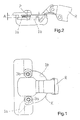
- FIG. 1 two retaining wings 1a, 1b, more specifically the wing 1a in a retaining position and the wing 1b at stand-by position are drawn in dotted lines.
- the figure shows a blade-type construction of the wings 1a, 1b with practical importance of said blade-type shape being in that the wing also functions as a unilaterally fastened girder of a substantially constant bending strength, from which it is expected to achieve an elastic adaptation of the girder to the given dimensions available for the installation, by means of the respective elastical flexibility.
- the wings 1a, 1b are positioned in an inclined way.
- two supporting faces of a cup core (details: hereinafter), the wings 1a, 1b act with, reside in a common plane, which forms an angle ⁇ (alpha) with the surface of the furniture panel, with said angle having its tip residing on the side of the cup member averted from a hinge arm R.
- each rotary element 3a, 3b said rotary element being preferably a rivet in this embodiment, is arranged normally to the wings 1a, 1b, i.e. also in an inclined way, with the wing 1a, 1b being connected to said rivet in a manner that there exists no relative rotation between them.
- the rivets 3a, 3b comprise screw driver heads, which does not mean that other embodiments, such as those providing levers of the prior art instead of the heads 3a, 3b, are excluded.
- the wing 1a, 1b In the stand-by position of the hinge, the wing 1a, 1b resides on the inner side of a circular contour K of a cup element of the respective cup member (the position of the wing 1b in FIG. 1).
- the rivet 3a, 3b By rotating the rivet 3a, 3b, each of them in a specific direction, the free tip portion of the wing 1a, 1b smoothly approaches to the inner side of a cover layer of said furniture panel and, after having reached it (the wing 1a in FIG. 1), it begins to get elastically deformed if further rotated.
- the position of the hinge is determined by nesting the cup element of the cup member in an appropriate recess (hole, receiver) made in the furniture panel, and the cup member is then fastened therein on the basis of two elastically deformed wings 1a, 1b that, from the inner side, thrust the cover layer of the three-layer panel and thus tighten the respective cup member to said panel.
Landscapes
- Engineering & Computer Science (AREA)
- Mechanical Engineering (AREA)
- Hinges (AREA)
Abstract

Description
- FIG. 1
- is a plan of an inventive rotary fastening element-type cup member of a foldable furniture hinge,
- FIG. 2
- is an elevation of the hinge cup member of FIG. 1,
- FIG. 3
- is an overhead projection of a monolithic cup core of the cup member of FIGS. 1, 2,
- FIG. 4
- is a section along the line IV-IV of FIG. 3,
- FIG. 5
- is a plan to FIG. 3, and
- FIG. 6
- shows an analogous projection, a section, and a plan as in FIGS. 3 to 5, yet regarding a two-piece cup core.
Claims (3)
- Cup member of a foldable furniture hinge, provided with two rotary fastening elements, with each of them providing a radially extending retaining wing (1a, 1b), which, in a non-installed state of the hinge, resides radially on the inner side of a contour of a respective receiving blind hole and in an installed state it resides on the outer side thereof, characterized in that the wing (1a, 1b) is positioned under a specific angle with respect to a cup element having a contour (K) in order to obtain, when incorporating, a smooth arcuate path of moving of a tip portion of said wing relatively to said stationary cup element, said path thus approaching to the outer surface of said furniture panel i.e. in a direction contrary to the direction of tightening the respective cup member.
- Cup member of claim 1, characterized in that said wing (1a, 1b) mates, in an abutting manner, a supporting face of a cup core or a respective section of said cup element serving as a cup core, whereby said cup core being a separate constructional component can be made of plastics or a metal and embodied as a monolithic or a two-part constructional component.
- Cup member of claim 2, characterized in that two supporting faces (4) of the cup core made of plastics, with which the two wings (1a, 1b) act, reside in a common plane forming together with the surface plane of the furniture panel an acute angle (α) with a tip thereof lying on the side of the cup member averted from the hinge arm (R).
Applications Claiming Priority (2)
| Application Number | Priority Date | Filing Date | Title |
|---|---|---|---|
| SI200300276A SI21667A (en) | 2003-11-12 | 2003-11-12 | Arc-shaped part of furniture joint hinges on rotating attachment elements |
| SI200300276 | 2003-11-12 |
Publications (2)
| Publication Number | Publication Date |
|---|---|
| EP1531225A2 true EP1531225A2 (en) | 2005-05-18 |
| EP1531225A3 EP1531225A3 (en) | 2007-01-24 |
Family
ID=34432641
Family Applications (1)
| Application Number | Title | Priority Date | Filing Date |
|---|---|---|---|
| EP04468020A Withdrawn EP1531225A3 (en) | 2003-11-12 | 2004-11-10 | Cup member of a foldable furniture hinge provided with two rotary fastening elements |
Country Status (2)
| Country | Link |
|---|---|
| EP (1) | EP1531225A3 (en) |
| SI (1) | SI21667A (en) |
Family Cites Families (2)
| Publication number | Priority date | Publication date | Assignee | Title |
|---|---|---|---|---|
| AT290057B (en) * | 1969-03-03 | 1971-05-25 | Grass Alfred Metallwaren | Box for attaching a hinge in a hole in a door or the like. |
| AT401795B (en) * | 1992-06-10 | 1996-11-25 | Blum Gmbh Julius | HINGE |
-
2003
- 2003-11-12 SI SI200300276A patent/SI21667A/en not_active IP Right Cessation
-
2004
- 2004-11-10 EP EP04468020A patent/EP1531225A3/en not_active Withdrawn
Also Published As
| Publication number | Publication date |
|---|---|
| EP1531225A3 (en) | 2007-01-24 |
| SI21667A (en) | 2005-06-30 |
Similar Documents
| Publication | Publication Date | Title |
|---|---|---|
| EP0066514B1 (en) | Foldable panel for storage space of an automotive vehicle or the like | |
| EP1009901B1 (en) | Mirrored door and method of making same | |
| JP5039516B2 (en) | Opening frame mounting structure for open / close fittings | |
| EP2857622B1 (en) | Door jamb for flush in-swing door | |
| US20030200628A1 (en) | Continuous door hinge with multi-plastic bearings | |
| AU2006224541B2 (en) | Frameless glass door | |
| US8863358B2 (en) | Adjustable hinge | |
| US5454144A (en) | Furniture hinge including base plate with claw member | |
| EP1531225A2 (en) | Cup member of a foldable furniture hinge provided with two rotary fastening elements | |
| US20060137140A1 (en) | Hinge shim and sheet thereof | |
| AU5967099A (en) | Door hinge with integrated door brake | |
| CN1821526B (en) | Insulating material fixing means | |
| CA2384919C (en) | Hinge | |
| US4996740A (en) | Door closer adapter/replacement assembly | |
| JPH0328126Y2 (en) | ||
| EP1445412B1 (en) | Adjustable frame | |
| JPH09195376A (en) | Filler | |
| CA2245949C (en) | Adjustable frame | |
| JP2579207Y2 (en) | Door assembly structure | |
| JP2010001604A (en) | Mounting structure of pivot hinge | |
| FI88193B (en) | Method and arrangement for installation of a hinge | |
| JP3261257B2 (en) | Door stop structure | |
| JPH0415657Y2 (en) | ||
| AU740726B2 (en) | A hinge for a french door | |
| RU37377U1 (en) | DOOR (OPTIONS) |
Legal Events
| Date | Code | Title | Description |
|---|---|---|---|
| PUAI | Public reference made under article 153(3) epc to a published international application that has entered the european phase |
Free format text: ORIGINAL CODE: 0009012 |
|
| AK | Designated contracting states |
Kind code of ref document: A2 Designated state(s): AT BE BG CH CY CZ DE DK EE ES FI FR GB GR HU IE IS IT LI LU MC NL PL PT RO SE SI SK TR |
|
| AX | Request for extension of the european patent |
Extension state: AL HR LT LV MK YU |
|
| PUAL | Search report despatched |
Free format text: ORIGINAL CODE: 0009013 |
|
| AK | Designated contracting states |
Kind code of ref document: A3 Designated state(s): AT BE BG CH CY CZ DE DK EE ES FI FR GB GR HU IE IS IT LI LU MC NL PL PT RO SE SI SK TR |
|
| AX | Request for extension of the european patent |
Extension state: AL HR LT LV MK YU |
|
| 17P | Request for examination filed |
Effective date: 20070629 |
|
| AKX | Designation fees paid |
Designated state(s): AT BE BG CH CY CZ DE DK EE ES FI FR GB GR HU IE IS IT LI LU MC NL PL PT RO SE SI SK TR |
|
| 17Q | First examination report despatched |
Effective date: 20071029 |
|
| STAA | Information on the status of an ep patent application or granted ep patent |
Free format text: STATUS: THE APPLICATION IS DEEMED TO BE WITHDRAWN |
|
| 18D | Application deemed to be withdrawn |
Effective date: 20090429 |