EP1531120B1 - Bicycle pedal assembly - Google Patents
Bicycle pedal assembly Download PDFInfo
- Publication number
- EP1531120B1 EP1531120B1 EP04021353A EP04021353A EP1531120B1 EP 1531120 B1 EP1531120 B1 EP 1531120B1 EP 04021353 A EP04021353 A EP 04021353A EP 04021353 A EP04021353 A EP 04021353A EP 1531120 B1 EP1531120 B1 EP 1531120B1
- Authority
- EP
- European Patent Office
- Prior art keywords
- bicycle
- cleat
- pedal
- clamping member
- bicycle pedal
- Prior art date
- Legal status (The legal status is an assumption and is not a legal conclusion. Google has not performed a legal analysis and makes no representation as to the accuracy of the status listed.)
- Expired - Fee Related
Links
Images


Classifications
-
- B—PERFORMING OPERATIONS; TRANSPORTING
- B62—LAND VEHICLES FOR TRAVELLING OTHERWISE THAN ON RAILS
- B62M—RIDER PROPULSION OF WHEELED VEHICLES OR SLEDGES; POWERED PROPULSION OF SLEDGES OR SINGLE-TRACK CYCLES; TRANSMISSIONS SPECIALLY ADAPTED FOR SUCH VEHICLES
- B62M3/00—Construction of cranks operated by hand or foot
- B62M3/08—Pedals
- B62M3/086—Attachments between shoe and pedal other than toe clips, e.g. cleats
-
- Y—GENERAL TAGGING OF NEW TECHNOLOGICAL DEVELOPMENTS; GENERAL TAGGING OF CROSS-SECTIONAL TECHNOLOGIES SPANNING OVER SEVERAL SECTIONS OF THE IPC; TECHNICAL SUBJECTS COVERED BY FORMER USPC CROSS-REFERENCE ART COLLECTIONS [XRACs] AND DIGESTS
- Y10—TECHNICAL SUBJECTS COVERED BY FORMER USPC
- Y10T—TECHNICAL SUBJECTS COVERED BY FORMER US CLASSIFICATION
- Y10T74/00—Machine element or mechanism
- Y10T74/21—Elements
- Y10T74/2164—Cranks and pedals
- Y10T74/2168—Pedals
- Y10T74/217—Pedals with toe or shoe clips
Landscapes
- Engineering & Computer Science (AREA)
- Chemical & Material Sciences (AREA)
- Combustion & Propulsion (AREA)
- Transportation (AREA)
- Mechanical Engineering (AREA)
- Footwear And Its Accessory, Manufacturing Method And Apparatuses (AREA)
- Mechanical Control Devices (AREA)
Description
- This invention generally relates to a bicycle pedal assembly. More specifically, the present invention relates clipless or step-in bicycle pedal assembly, which has cleats that are releasble coupled to a pair of bicycle pedals.
- Bicycling is becoming an increasingly more popular form of recreation as well as a means of transportation. Moreover, bicycling has become a very popular competitive sport for both amateurs and professionals. Whether the bicycle is used for recreation, transportation or competition, the bicycle industry is constantly improving the various components of the bicycle as well as the frame of the bicycle. One component that has been extensively redesigned is the bicycle pedal.
- In recent years, bicycle pedals have been designed for specific purposes such as for pleasure, off road biking, road racing, etc. One particular type of bicycle pedal, which is gaining more popularity, is the step-in or clipless pedal, which releasably engages a cleat secured to the sole of a cyclist's shoe. The clipless pedal has a pedal spindle that can be mounted on the crank of a bicycle, a pedal body that is rotatably supported on this pedal spindle, and a cleat engagement mechanism. In an off road bicycle pedal a cleat engagement mechanism is formed on both sides of the pedal body for engaging a cleat. A road-racing pedal, on the other hand, typically only has a cleat engagement mechanism on one side of the pedal body. In either case, in these types of bicycle pedals, the rider steps onto the pedal and the cleat engagement mechanism automatically grips on to the cleat secured to the bottom of the cyclist's shoe.
- With this type of step-in or clipless pedal, such as expressed under
US 6,151,989 ,EP 0 619219 A1 ,US 5,419,218 orUS 5 131 291 , the shoe and the pedal are in a state of constant engagement when the cleat is engaged in the cleat clamping members, so the pedaling force can be transmitted efficiently to the pedals. As a result, step-in or clipless pedals are widely employed on racing bicycles used in road racing and mountain bike racing. - When attaching the cyclist's shoe to the step-in or clipless pedal via the cleat, the cyclist moves the shoe obliquely downwardly and forwardly relative to the pedal body such that the front end of the cleat engages a front hook or clamping member of the pedal body. Once the front end of the cleat is engaged with the front hook of the pedal body, the cyclist places the rear end of the cleat in contact with a guide portion of the rear hook or clamping member of the pedal body. In this position, the cyclist presses the shoe downwardly against the pedal to cause the rear hook or clamping member to initially pivot rearwardly against the force of a spring to move the rear hook or clamping member to a cleat releasing position. The rear end of the cleat then enters a position opposite a back face of the rear hook or clamping member. Then, the rear hook or clamping member returns under the force of a biasing member or spring so that the rear hook or clamping member engages the rear end of the cleat. This engagement fixes the cyclist's shoe to the pedal via the cleat.
- When releasing the shoe from the pedal, the cyclist will typically turn the shoe about an axis perpendicular or approximately perpendicular to the tread of the pedal, using the front end of the cleat as a pivoting point. As a result of this pivoting action, the rear hook or clamping member is pivoted rearwardly against the force of the spring to a cleat releasing position to release the shoe. It is important that the cleat does not inadvertently release the pedal during normal pedaling. Some of these prior step-in or clipless pedals can inadvertently release the cleat during normal pedaling if the spring force on the rear clamping member is set too low. However, if the spring force on the rear clamping member is set too high, the cleat may not release from the pedal properly. This could result in the rider's shoe not properly releasing from the pedal at the desired application of force because the rider's shoe either releases too easily from the pedal or does not release at the proper time. Thus, some of these step-in or clipless pedals and the cleats for these pedals are designed with adjustment mechanisms to change the release force required for the rider to disengage the cleat from the pedal. However, these adjustment mechanisms increase the overall cost of the pedals. In particular, these adjustment mechanisms can be complicated and expensive to manufacture and assemble.
- In view of the above, there exists a need for an improved bicycle pedal assembly that takes into account at least come of the above mentioned problems in the prior art. This invention addresses this need in the prior art as well as other needs, which will become apparent to those skilled in the art from this disclosure.
- One object of the present invention is to provide a bicycle pedal assembly that is configured and arranged such that the release force can be adjusted without an adjustment mechanism for the clamping members.
- Another object of the present invention is to provide a step-in bicycle pedal assembly that is relatively lightweight and malfunction free.
- Yet another object of the present invention is to provide a step-in bicycle pedal assembly that is relatively simple and inexpensive to manufacture.
- The foregoing objects can basically be achieved by providing a bicycle pedal assembly comprising a bicycle pedal and a pair of bicycle cleat. The bicycle pedal basically comprises a pedal shaft, a pedal body, a front clamping member and a rear clamping member. The pedal shaft has a center rotational axis. The pedal body is rotatably coupled to the pedal shaft about the center rotational axis of the pedal shaft. The pedal body has a first end and a second end with a center plane extending between the first and second ends and passing through the center rotational axis of the pedal shaft. The front clamping member is coupled to the first end of the pedal body. The front clamping member has a front cleat engagement surface facing towards the center plane of the pedal body. The rear clamping member is coupled to the second end of the pedal body. The rear clamping member has a rear cleat engagement surface facing towards the center plane of the pedal body. The first bicycle shoe cleat includes first front and rear attachment portions configured and arranged to cooperate with the front and rear clamping members to release the first bicycle shoe cleat from a cleat engaged position to a cleat released position upon application of a first predetermined amount of outward twisting force. The second bicycle shoe cleat includes second front and rear attachment portions configured and arranged to cooperate with the front and rear clamping members to release the second bicycle shoe cleat from the cleat engaged position to the cleat released position upon application of a second predetermined amount of outward twisting force that is higher than the first predetermined amount of outward twisting force.
- These and other objects, features, aspects and advantages of the present invention will become apparent to those skilled in the art from the following detailed description, which, taken in conjunction with the annexed drawings, discloses a preferred embodiment of the present invention.
- Referring now to the attached drawings which form a part of this original disclosure:
-
Figure 1 is a side elevational view of a bicycle that is equipped with a pair of bicycle pedals in accordance with a preferred embodiment of the present invention; -
Figure 2 is a top plan view of a pair of bicycle pedal assemblies in a first arrangement with the cleats being arranged to produce a low cleat release force in accordance with the preferred embodiment of the present invention; -
Figure 3 is a top plan view of the pair of bicycle pedal assemblies illustrated inFigure 2 with the cleats being rotated by a first predetermined outward twisting force; -
Figure 4 is a top plan view of the pair of bicycle pedal assemblies in a second arrangement with the cleats being arranged to produce a high cleat release force in accordance with the preferred embodiment of the present invention; -
Figure 5 is a top plan view of the pair of bicycle pedal assemblies illustrated inFigure 4 with the cleats being rotated by a second predetermined outward twisting force; -
Figure 6 is a side elevational view of the right bicycle pedal illustrated inFigures 2-5 , with the rear clamping member of the right bicycle pedal pivoted to a release position that corresponds to with the cleat being rotate relative to the right bicycle pedal by application of the first or second predetermined outward twisting force; -
Figure 7 is an inside side elevational view of the right bicycle pedal illustrated inFigures 2-6 , without a cleat coupled thereto; -
Figure 8 is an outside elevational view of the right bicycle pedal illustrated inFigures 2-7 , without the cleat coupled thereto; -
Figure 9 is a top plan view of the right bicycle pedal illustrated inFigures 2-8 , without a cleat coupled thereto; -
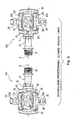
Figure 10 is a rear end elevational view of the right bicycle pedal illustrated inFigures 2-9 , without the cleat coupled thereto; -
Figure 11 is a longitudinal cross-sectional view of the bicycle pedal assembly illustrated inFigures 5 and6 , as seen along section line 11-11 ofFigure 10 , without the cleat coupled thereto; -
Figure 12 is a top plan view of the right bicycle pedal body for the right bicycle pedal illustrated inFigures 3-11 ; -
Figure 13 is an inside elevational view of the right bicycle pedal body illustrated inFigure 12 for the right bicycle pedal illustrated inFigures 3-11 ; -
Figure 14 is a transverse cross-sectional view of the right bicycle pedal body illustrated inFigures 12 and 13 for the bicycle pedal illustrated inFigures 3-11 as seen along section line 14-14 ofFigure 12 ; -
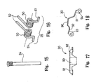
Figure 15 is a side perspective view of one of the pivot pins for pivotally coupling one of the clamping members to the bicycle pedal bodies illustrated inFigures 2-5 ; -
Figure 16 is a perspective view of one of the biasing members (a pair of torsion springs) for urging one pair of the clamping members of the bicycle pedal assemblies to the rest or cleat engaging positions; -
Figure 17 is a top plan view first side elevational view of one of the pedal body covers for the bicycle pedal assemblies illustrated inFigures 2-5 ; -
Figure 18 is a side elevational view of the pedal body cover illustratedFigure 17 for the bicycle pedal assemblies illustrated inFigures 2-5 ; -
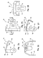
Figure 19 is a side elevational view of the front clamping member for the bicycle pedal assemblies illustrated inFigures 2-5 ; -
Figure 20 is a top plan view of the front clamping member illustrated inFigure 19 for the bicycle pedal assemblies illustrated inFigures 2-5 ; -
Figure 21 is a rear end elevational view of the front clamping member illustrated inFigures 19 and 20 for the bicycle pedal assemblies illustrated inFigures 2-5 ; -
Figure 22 is a cross-sectional view of the front clamping member illustrated inFigures 19-21 for the bicycle pedal assemblies illustrated inFigures 2-5 , as seen along section line 22-22 ofFigure 20 ; -
Figure 23 is an oblique view of the front clamping member illustrated inFigures 19-22 for the bicycle pedal assemblies illustrated inFigures 2-5 ; -
Figure 24 is a side elevational view of the front clamping member for the bicycle pedal assemblies illustrated inFigures 2-5 ; -
Figure 25 is a top plan view of the front clamping member illustrated inFigure 24 for the bicycle pedal assemblies illustrated inFigures 2-5 ; -
Figure 26 is a rear end elevational view of the front clamping member illustrated inFigures 24 and 25 for the bicycle pedal assemblies illustrated inFigures 2-5 ; -
Figure 27 is a cross-sectional view of the front clamping member illustrated inFigures 24-26 for the bicycle pedal assemblies illustrated inFigures 3-11 , as seen along section line 27-27 ofFigure 25 ; -
Figure 28 is an oblique view of the front clamping member illustrated inFigures 24-27 for the bicycle pedal assemblies illustrated inFigures 2-5 ; -
Figure 29 is a front end elevational view of the first cleat for use with both the right bicycle pedal and the left bicycle pedal illustrated inFigures 2-5 -
Figure 30 is a side elevational view of the first cleat illustrated inFigure 29 for use with both the right bicycle pedal and the left bicycle pedal illustrated inFigures 2-5 ; -
Figure 31 is a rear end elevational view of the first cleat illustrated inFigures 29 and 30 for use with both the right bicycle pedal and the left bicycle pedal illustrated inFigures 2-5 ; -
Figure 32 is a bottom plan view of the first cleat illustrated inFigures 29-31 for use with both the right bicycle pedal and the left bicycle pedal illustrated inFigures 2-5 ; -
Figure 33 is a top plan view of the first cleat illustrated inFigures 29-32 for use with both the right bicycle pedal and the left bicycle pedal illustrated inFigures 2-5 ; -
Figure 34 is a front end elevational view of the second cleat for use with both the right bicycle pedal and the left bicycle pedal illustrated inFigures 2-5 ; -
Figure 35 is a side elevational view of the second cleat illustrated inFigure 29 for use with both the right bicycle pedal and the left bicycle pedal illustrated inFigures 2-5 ; -
Figure 36 is a rear end elevational view of the second cleat illustrated inFigures 34 and 35 for use with both the right bicycle pedal and the left bicycle pedal illustrated inFigures 2-5 ; -
Figure 37 is a bottom plan view of the second cleat illustrated inFigures 34-36 for use with both the right bicycle pedal and the left bicycle pedal illustrated inFigures 2-5 ; -
Figure 38 is a top plan view of the second cleat illustrated inFigures 34-37 for use with both the right bicycle pedal and the left bicycle pedal illustrated inFigures 2-5 ; -
Figure 39 is a side elevational view of a left bicycle shoe with one of the cleats of the present invention coupled thereto, prior to coupling of the cleat to the left bicycle pedal; -
Figure 40 is a side elevational view of a left bicycle shoe with one of the cleats of the present invention coupled thereto, prior to coupling of the cleat to the left bicycle pedal; -
Figure 41 is a side elevational view of a left bicycle shoe with one of the cleats of the present invention coupled thereto, prior to coupling of the cleat to the left bicycle pedal; and -
Figure 42 is a side elevational view of a left bicycle shoe with one of the cleats of the present invention coupled thereto, prior to coupling of the cleat to the left bicycle pedal. - Selected embodiments of the present invention will now be explained with reference to the drawings. It will be apparent to those skilled in the art from this disclosure that the following descriptions of the embodiments of the present invention are provided for illustration only and not for the purpose of limiting the invention as defined by the appended claims and their equivalents.
- Referring initially to
Figure 1 , abicycle 10 is illustrated that is equipped with aleft bicycle pedal 12a and aright bicycle pedal 12b in accordance with a first embodiment of the present invention. The bicycle thepedals arms bicycle 10 for rotation therewith. - As seen in
Figures 2-5 , the left andright bicycle pedals right bicycle pedals bicycle pedals - In the illustrated embodiment, the
bicycle pedals bicycle pedals bicycle pedals bicycle pedals - Specifically, the cleats A and B are engaged with the
bicycle pedals pedals pedals pedals pedals - The first and second bicycle shoe cleats A and B are configured and arranged to selectively cooperate with the
bicycle pedals Figures 2 and3 , the first and second bicycle shoe cleats A and B are configured and arranged to release upon application of a first predetermined amount of outward twisting force F1 when the first bicycle shoe cleat A is engaged with theleft bicycle pedal 12a and the second bicycle shoe cleat B is engaged with theright bicycle pedal 12b. - However, as illustrated in
Figures 4 and5 , the first and second bicycle shoe cleats A and B are configured and arranged to release upon application of a second predetermined amount of outward twisting force F2 that is higher than the first predetermined amount of outward twisting force F1 when the first bicycle shoe cleat A is engaged with theright bicycle pedal 12b and the second bicycle shoe cleat B is engaged with theleft bicycle pedal 12a. - As seen in
Figures 2-5 , theleft bicycle pedal 12a is a mirror image of theright bicycle pedal 12b. It will be apparent to those skilled in the art from this disclosure that the description of theleft bicycle pedal 12a also applies to theright bicycle pedal 12b and vice a versa. Thus, the same reference numerals will be used to describe both the left andright pedals left bicycle pedal 12a will not be discussed or illustrated in further detail herein for the sake of brevity. - The left and the
right bicycle pedals spindle 21, apedal body 22, a pair of front (first) clampingmembers 23 pivotally coupled to thepedal body 22 by a pair of pivot pins 24, a pair of rear (second) clampingmembers 25, a pair ofspring holders 26 and a pair of biasingmembers 28. Also, thepedal body 22 preferably includes two pairs of pedal body covers 30 that overlie a center upper portion of thepedal body 22 to protect thepedal body 22 from scratches. Thepedals Figure 8 . - As shown in
Figure 1 , thepedal spindles 21 are fastened to the crankarms bicycle 10, with thepedal bodies 22 being rotatably coupled to thepedal spindle 21 for supporting the rider's feet. Specifically, the cleats A and B are fixedly attached to the bicycle shoes, which in turn are releasably attached to thepedal bodies 22 via one of the pairs of the front andrear clamping members - The
pedal spindle 21 is a multi-step spindle having numerous stepped portions. Thepedal spindle 21 has afirst end 31 with threads formed thereon for threadedly coupling bicycle pedal to thecrank arm pedal spindle 21 rotatably supports thepedal body 22 in a conventional manner. Thepedal body 22 can freely rotate about the center rotational axis R of thepedal spindle 21. Since thepedal spindle 21 is relatively conventional and its specific construction is not critical to the present invention, the construction of thepedal spindle 21 will not be discussed in detail herein. - As shown in
Figures 12-14 , thepedal body 22 is an H-shaped member (seeFigure 12 ) that basically includes acenter tubular portion 41, an innerside mounting portion 42 and an outerside mounting portion 43. Thepedal body 22 is a rigid member that is preferably made as a one-piece, unitary member from a lightweight material such as an aluminum alloy. As best seen inFigures 9-11 , thepedal body 22 is rotatably coupled to thepedal spindle 21 for rotation about a center rotational axis R of thepedal spindle 21. - In particular, the
center tubular portion 41 has a stepped bore 44 (seeFigure 14 ) for receiving thepedal spindle 21 for rotation about the center rotational axis R. Theside mounting portions members side mounting portion 42 extends in a forward and backward direction from an inner end of thecenter tubular portion 41. Theside mounting portions pedal body 22. The cover receiving recesses 45 are configured and arranged to receive the pedal body covers 30, respectively. - The inner
side mounting portion 42 has a pair of threaded holes or bores 46 that threadedly receive the pivot pins 24 therein. The outerside mounting portion 43 extends in a forward and backward direction from an outer end of thecenter tubular portion 41. The outerside mounting portion 43 has a pair ofblind bores 47 that receives the free ends of the pivot pins 24 therein. The unthreaded blind bores 47 are axially aligned with the threaded bores 46 for receiving the outer end of the pivot pins 24. Thebores pedal body 22 can be formed. In other words, the threaded bores 46 aids in providing an attractive appearance, since the heads of the pivot pins 24 are not visible from the outside of thepedal body 22. One of thefront clamping members 23 is pivotally mounted at each end of thepedal body 22 by one of the pivot pins 24. Likewise, one of therear clamping members 25 is pivotally mounted at each end of thepedal body 22 by one of the pivot pins 24. - The
pedal body 22 has a center longitudinal line CL extending between the front and the rear ends as seen inFigure 10 . The center longitudinal line CL of thepedal body 22 extends substantially perpendicular to the center rotational axis R of thepedal spindle 21 and bisects the clampingmembers pedal body 22 also has a center plane P1 extending between the first and second ends of thepedal body 22 with the center plane P1 passing through the center rotational axis R of thepedal spindle 21 and the centers ofbores Figures 11 and13 . The center plane P1 divides thepedal body 22 into first and second cleat engagement sides. A cleat receiving area is formed on each side ofpedal body 22 for receiving and supporting the cleats A and B thereon. More specifically, the cleat receiving area is defined the area extending longitudinally between the clampingmembers pedal body 22. Thus, the cleats A and B are designed to releasably couple a sole of a shoe to thebicycle pedals rear clamping members pedal body 22 relative to the center plane P1. - Each biasing
member 28 is preferably formed by a pair of torsion springs. The torsion springs of the biasingmembers 28 have their coiledportions 50 mounted on the pivot pins 24, with oneend 51 of each spring engaging a part of one of thefront clamping members 23, and theother end 52 of each spring engaging a part of one of therear clamping members 25. The biasingmembers 28 normally urge clampingmembers members 28 normally maintain the clampingmembers members 28 of the clampingmembers pedals - Referring back to
Figures 2-5 , the clampingmembers members pedal body 22 by the pivot pins 24. As seen inFigure 10 , the clampingmembers pedal body 22, with their two free ends being swingably supported by the pivot pins 24 that pass between the inner and outerside mounting portions pedal body 22. - Referring now to
Figures 19-23 , each of thefront clamping members 23 includes a connectingportion 60 with a pair oflegs 61 extending downwardly from connectingportion 60 for coupling thefront clamping member 23 to thepedal body 22 via one of the pivot pins 24. More specifically, each of thelegs 61 of thefront clamping members 23 has a mountinghole 63 formed therein for receiving one of the pivot pins 24. Accordingly, each of thefront clamping members 23 is pivotally mounted about itsrespective pivot pin 24 for movement between a cleat clamping or engaging position and a cleat releasing position. - Each of the connecting
portions 60 of thefront clamping members 23 has a front cleat engagement portion orsurface 64 and a front cleat stop portion orsurface 65. The frontcleat engagement surface 64 faces generally towards the center plane P1 of thepedal body 22, while the frontcleat stop surface 65 is spaced forwardly from the center rotational axis R of thepedal spindle 21 by a first predetermined distance d1 measured parallel to the frontcleat engagement surface 64 as seen inFigures 8 and11 . The frontcleat engagement surface 64 of each front clampingmember 23 is configured and arranged to engage a front portion of the cleats A and B to limit movement of the cleats A an B away from the pedal body. The frontcleat stop surface 65 of each front clampingmember 23 is configured and arranged to engage a front portion of the cleats A and B to limit forward movement of the cleats A and B. The frontcleat engagement surface 64 is a flat planar surface. The frontcleat stop surface 65 is a flat planar surface that extends substantially perpendicular to the frontcleat engagement surface 64. - Each of the
legs 61 of thefront clamping members 23 also has a first stop portion orflange 66 and a second stop portion orflange 67. Thefirst stop portions 66 of each of thefront clamping members 23 are configured and arranged to engage thepedal body 22 to limit rotational movement of the front clampingmember 23 in a first rotational direction about the respective one of the pivot pins 24. Thesecond stop portions 67 of each of thefront clamping members 23 are configured and arranged to engage thepedal body 22 to limit rotational movement of the front clampingmember 23 in a second rotational direction about the respective one of the pivot pins 24. More specifically, thefirst stop portions 66 of each of thefront clamping members 23 are normally biased against thepedal body 22 by the respective one of the biasingmembers 28. Thesecond stop portions 67 of each of thefront clamping members 23 are normally spaced frompedal body 22 by a predetermined amount. Thus, as seen inFigure 6 , thefront clamping members 23 can pivot about the pivot pins 24 against the urging forces of the biasingmembers 28 such that thefront clamping members 23 can pivot in a generally forward direction by a first predetermined rotational distance or amount θ1. Preferably, thefront clamping members 23 can pivot in a generally forward direction by approximately three degrees to about five degrees as measured about the center axis of the respective one of the pivot pins 24. - Referring now to
Figures 24-28 , each of therear clamping members 25 includes a connectingportion 70 with a pair oflegs 71 extending downwardly from connectingportion 70 for coupling therear clamping member 25 to thepedal body 22 via one of the pivot pins 24. More specifically, each of thelegs 71 of therear clamping members 25 has a mountinghole 73 formed therein for receiving one of the pivot pins 24. Accordingly, each of therear clamping members 25 is pivotally mounted about itsrespective pivot pin 24 for movement between a cleat clamping or engaging position and a cleat releasing position. - Each of the connecting
portions 70 of therear clamping members 25 has a rear cleat engagement portion orsurface 74 and a rear cleat stop portion orsurface 75. The rearcleat engagement surface 74 faces generally towards the center plane P1 of thepedal body 22. The rearcleat stop surface 75 is spaced rearwardly from the center rotational axis R of thepedal spindle 21 by a second predetermined distance d2 measured parallel to the rearcleat engagement surface 74 as seen inFigures 8 and11 . The rearcleat engagement surface 74 of each rear clampingmember 25 is configured and arranged to engage a rear portion of the cleats A and B to limit movement of the cleats A an B away from the pedal body. The rearcleat stop surface 75 of each rear clampingmember 25 is configured and arranged to engage a rear portion of the cleats A and B to limit rearward movement of the cleats A and B. The rearcleat engagement surface 75 is a flat planar surface. The rearcleat stop surface 75 is a flat planar surface that extends substantially perpendicular to the rearcleat engagement surface 74. - Each of the
legs 71 of therear clamping members 25 also has astop surface 76 that is configured and arranged to engage thepedal body 22 to limit rotational movement of therear clamping member 25 in a first rotational direction about the respective one of the pivot pins 24, i.e., hold therear clamping member 25 in rest or cleat engaging position. More specifically, the stop surfaces 76 of each of therear clamping members 25 are normally biased against thepedal body 22 by the respective one of the biasingmembers 28. Thus, therear clamping members 25 can pivot about the pivot pins 24 against the urging forces of the biasingmembers 28 such that therear clamping members 25 can pivot in a generally rearward direction by a predetermined rotational distance or amount θ2, as seen inFigure 6 . Preferably, the predetermined rotational distance θ2 is about thirteen degrees, when the pedal and cleat are arranged to require the first predetermined outward twisting force F1 and about fourteen degrees, when the pedal and cleat are arranged to require the second predetermined outward twisting force F2. Preferably, therear clamping members 25 can pivot in a generally rearward direction by at least fourteen degrees as measured about the center axis of the respective one of the pivot pins 24. - As seen in
Figure 11 , first and second cleat engagement surfaces 64 and 74 preferably lie in substantially the same plane, which forms an acute angle with the center plane P1. Thus, the first and second cleat engagement surfaces 64 and 74 hold the cleat A or B from moving vertically from thepedal body 22. Preferably, the firstcleat engagement surface 64 is spaced from the pivot axis of thepivot pin 24 by a predetermined distance L1, while the secondcleat engagement surface 74 is spaced from the pivot axis of thepivot pin 24 by a predetermined distance L2 that is larger than the predetermined distance L1. The first and second cleat stop surfaces 65 and 75 hold the cleat A or B from moving in a front to rearward direction of thepedal body 22. Preferably, the first and second cleat stop surfaces 65 and 75 are spaced apart by a predetermined distance S1. Moreover, the secondcleat stop surface 75 is spaced (offset) from the center rotational axis R of thepedal spindle 21 by the predetermined distance d2, while the firstcleat stop surface 65 is spaced (offset) from the center rotational axis R of thepedal spindle 21 by the predetermined distance d1 that is larger than the predetermined distance d2. The dimensions d1 and d2 are measured along a plane that extends perpendicular to the first and second cleat stop surfaces 65 and 75. Since dimension d1 is greater than the dimension d2, the step-in torque is approximately 17% greater than if the dimensions d1 and d2 were equal. - As seen in
Figures 24-28 , therear clamping members 25 are provided with a generallyhorizontal portion 77 and a generallyvertical portion 78. Theportions real body 22 to horizontal position for engagement as seen inFigures 39 and 40 . As seen inFigure 11 , the generallyhorizontal portion 77 extends in a substantially rearward direction past the end of thepedal body 22 by a predetermined distance S2 that is at least substantially equal to or greater than the predetermined distance S1. The generallyhorizontal portion 77 of therear clamping members 25 is provided with anopening 79 for receiving thespring holder 26 to couple the second ends 52 of the torsion springs that form the biasingmember 28 to therear clamping member 25. - Referring now to
Figures 17 and 18 , each of the pedal body covers 30 basically includes aprotective body portion 90, afirst attachment leg 91 and asecond attachment leg 92. The first andsecond attachment legs pedal body 22 by the pivot pins 24. Each of the pedal body covers 30 is a rigid member that is preferably made as a one-piece, unitary member from a material that is harder than the material of thepedal body 22 such as stainless steel. There are four of the pedal body covers 30 with two of the pedal body covers 30 mounted on each side of thepedal body 22 in the cover receiving recesses 45. In particular, the pedal body covers 30 are located at the ends of thecenter tubular portion 41 in the area where the cleat A or B will rub against thepedal body 22 if the pedal body covers 30 were removed. - Referring now to
Figures 29-38 , the cleats A and B are basically mirror images of each other. It will be apparent to those skilled in the art from this disclosure that the descriptions of the portions of the cleat A (Figures 29-33 ) also to applies to the corresponding portions of the cleat B (Figures 34-38 ) and vice a versa. Thus, the same reference numerals will be used to describe both the portions of the cleat A and the corresponding portions of the cleat B for the sake of brevity. - Basically, each of the cleats A and B includes an
attachment portion 100, a first or front coupling portion ormember 101 extending from one end of theattachment portion 100 and a second or rear coupling portion ormember 102 extending from the other end of theattachment portion 100. The front coupling portion ormember 101 has a pair of lateral front corner abutments CF1 and CF2, while the rear coupling portion ormember 102 has a pair of lateral rear corner abutments CR1 and CR2. The front corner abutments CF1 and CF2 selectively contact thefront clamping member 23 when the cleat is pivoted about its pivot axis P of the cleat A or B, while the rear corner abutments CR1 and CR2 selectively contact therear clamping member 25 when the cleat is pivoted about its pivot axis P of the cleat A or B. The pivot axis P is located at the intersection of a first line that extends between the front and rear corner abutments CF1 and CR1 and a second line that extends between the front and rear corner abutments CF2 and CR2 as seen inFigures 33 and38 . The pivot axis P also lies on a center line CL of the cleat A or B. As seen inFigures 32 and37 , the front and rear corner abutments CF1 and CR1 are spaced laterally from the center line CL of the cleat A or B by a first lateral distance DL1, while the front and rear corner abutments CF2 and CR2 are spaced laterally from the center line CL of the cleat A or B by a second lateral distance DL2 that is larger than the first lateral distance DL1. This arrangement at least partially results in the low outward twisting force F1 and the high outward twisting force F2 for release the cleat A or B depending on which of the cleats A and B are used with which of thepedals - The
attachment portion 100 has an uppersole side 103 facing in a first direction for engaging the sole of the shoe and a lower pedal side facing 104 in a second direction which is substantially opposite to the first direction. Preferably theattachment portion 100 and thecoupling portions - The
attachment portion 100 has a pair of hole or slot 105 for receiving one or more fasteners for fixedly coupling to the sole of the cyclist's shoe in a relatively conventional manner. The interconnection of the cleat A to the sole is relatively well known in the art, and thus, this interconnection will not be discussed or illustrated in detail herein. - The
front coupling portion 101 is designed to engage thefront clamping member 23. Thefront coupling portion 101 has a nose portion orflange 106 with a first orfront coupling surface 106a, a centerfront stop surface 107 and a pair of lateral front stop surfaces 108. Thefront coupling surface 106a faces towards the sole of the shoe, while the front stop surfaces 107 and 108 extend substantially perpendicular to thefront coupling surface 106a. The centerfront stop surface 107 is designed to engage thefront stop surface 65 of the front clampingmember 23 to prevent forward movement of the cleats relative to thepedal body 22. - The center front stop surfaces 107 is arranged to extend perpendicular to a center line CL of the cleat A or B that divides the
front coupling surface 106a into two equal side portions. The lateral front stop surfaces 108 are angled relative to the center front stop surfaces 107 so that they are inclined rearwardly as they extend outwardly from the center front stop surfaces 107. Preferably, the lateral front stop surfaces 108 are angled about five degrees relative to the center front stop surfaces 107. The lateral front stop surfaces 108 are designed to engage thefront stop surface 65 of the front clampingmember 23 when the cleat is pivoted about its pivot axis P of the cleat A or B. The lateral front stop surfaces 108 form the front lateral corner abutments CF1 and CF2 that are spaced from the center line CL of the cleat A or B. The front lateral corner abutment CF1 is spaced a shorter distance from the center line CL of the cleat A or B than the front lateral corner abutment CR2 from the center line CL of the cleat A or B. Thus, the rear lateral corner abutment CR1 forms a low force rear corner abutment, while the rear lateral corner abutment CR2 forms a high force rear corner abutment. - The second or
rear coupling portion 102 extends from the second end of theattachment portion 100. Therear coupling portion 102 is designed to engage therear clamping member 25. Therear coupling portion 102 has a nose portion orrear flange 109 and a centerrear stop surface 110 and a pair of lateral rear stop surfaces 111. The nose portion orrear flange 109 includes a second orrear coupling surface 109a and arear edge 109b extending perpendicularly relative to therear coupling surface 109a. Therear edge 109b includes corners CRR1 and CRR2 that define the release points of therear flange 109. In other words, when the cleat A or B is pivoted about its pivot axis P of the cleat A or B, therear flange 109 will be twisted outwardly from underneath therear clamping member 25. The cleat A or B will release from therear clamping member 25 when one of the corners CRR1 and CRR2 of therear flange 109 aligns with therear stop surface 75 of therear clamping member 25. In other words, when one of the corners CRR1 and CRR2 of therear flange 109 can be seen from above, the rear flange of the cleat A or B releases from therear stop surface 75 of therear clamping member 25. The corner CRR1 is located on the same side of the center line CL as the rear lateral corner abutment CR1, while the corner CRR2 is located on the same side of the center line CL as the rear lateral corner abutment CR2. Therear flange 109 is shifted from the center line CL towards the rear lateral corner abutment CR2 by an OFFSET distance to control the release angle. Thus, the corners CRR1 and CRR2 of therear flange 109 are symmetrically arranged about the OFFSET axis that is parallel to the center line CL. Preferably, in the preferred embodiment, the OFFSET distance is about 0.65 mm from the center line CL of the cleat A or B towards the rear lateral corner abutment CR2. Preferably, this OFFSET distance is dimensioned together with the corners CRR1 and CRR2 of therear flange 109 and the rear lateral corner abutments CR1 and CR2 such that the release angle (e.g., 15°) is substantially identical for each of the cleats A and B whether used with theleft pedal 12a or theright pedal 12b. - The
rear coupling surface 109a faces towards the sole of the shoe, while the rear stop surfaces 110 and 111 extend substantially perpendicular to therear coupling surface 110. The rear stop surfaces 110 and 111 are designed to engage thestop surface 75 of therear clamping member 25 to prevent rearward movement of the cleat A or B relative to thepedal body 22. Preferably, thecoupling surfaces - The lateral rear stop surfaces 111 are angled relative to the center
rear stop surface 110 so that they are inclined forwardly as they extend outwardly from the centerrear stop surface 110. Preferably, the lateral rear stop surfaces 111 are angled about five degrees relative to the centerrear stop surface 110. The lateral rear stop surfaces 111 are designed to engage therear stop surface 75 of therear clamping member 25 when the cleat A or B is pivoted about its pivot axis P of the cleat A or B. - The rear stop surfaces 110 and 111 are symmetrically arranged about an OFFSET that is spaced by 0.65 mm to one side of the cleat A or B from the center line CL of the cleat A or B. The lateral rear stop surfaces 111 form the rear lateral corner abutments CR1 and CR2 that are spaced from the center line CL of the cleat A or B. The rear lateral corner abutments CR1 and CR2 form
effective lever arms lever arm 112 is shorter than thelever arm 113. The lateral corner abutment CR1 is spaced a shorter distance from the center line CL of the cleat A or B than the lateral corner abutment CR2 from the center line CL of the cleat A or B. Thus, when the lateral corner abutment CR1 engages therear stop surface 75 of therear clamping member 25 upon the application of an outward twisting force, the cleat A or B easier to pivot to the release position than the lateral corner abutment CR2 engages therear stop surface 75 of therear clamping member 25. - One preferred assembly operation of the
bicycle pedals bicycle pedals rear clamping members bicycle pedal body 22 by the pivot pins 24. This is done by positioning the front andrear clamping members side mounting portions second attachment legs members 28 are held in place between the front andrear clamping members pedal body 22 such that the front andrear clamping members members 28 and the pedal body covers 30 are mounted on the pivot pins 24. Thus, the pedal body covers 30 are fixedly coupled to thepedal body 22 by the pivot pins 24, while the front andrear clamping members pedal body 22 by the pivot pins 24. In this state the biasingmembers 28 are not in their fully preloaded state. Thus, the springs of the biasingmembers 28 are now wound about the pivot pins 24 and thespring holders 26 are insert into openings of therear clamping members 25 to properly preload the biasingmembers 28, which urge the front andrear clamping members members 28 to be initially installed in unload or load loaded state for easy assembly. In other words, the front andrear clamping members members 28 can be installed on thebicycle pedal body 22 without having to preloaded the biasingmembers 28 under high tension. - Operation of the
bicycle pedal 12b will now be briefly described with reference mainly toFigures 39-40 . Due to the unique construction of thebicycle pedals pedal Figures 39 and 40 to a substantially horizontal position as seenFigures 41 and 42 . When a bicycle shoe is to be attached to one of thebicycle pedal 12a, the rider can rotate thepedal 12a from the non-horizontal position shown inFigure 39 to a substantially horizontal position as seenFigures 41 and 42 , by rotating thebicycle pedal 12a in a counter clockwise direction. Because the front andrear clamping members rear clamping members 25 are offset from the axis R, the rider can easily rotate thepedal 12a. Moreover, when thepedal 12a is in the non-horizontal position shown inFigure 40 , the rider can easily rotate thepedal 12a in either direction. - Once the
pedal 12a is in a substantially horizontal position as seenFigures 41 and 42 , the rider moves the tip of the shoe forward towards one of thefront clamping members 23 so that the tip of the cleat A or B is inserted underneath one of thefront clamping members 23. Once the tip of the cleats A and B has been inserted underneath one of thefront clamping members 23, a downwardly directed force is applied by the shoe, such that the shoe is pushed down toward thebicycle pedal body 22. When the shoe is pressed down further from this state shown inFigures 41 and 42 , the rear end of the cleat A or B rotates one of therear clamping members 25 backward against the biasing force of one of the biasingmembers 28. Simultaneously, the front end of the cleat A or B rotates the front clampingmember 25 forward against the biasing force of the other one of the biasingmembers 28. The cleat A or B then slides between the front and rear clampingmember member member members 28 back to their original positions. As a result, the cleat A or B is engaged between the front and rear clampingmember 23 and 25 (seeFigure 2 ). - When the shoe is to be removed from the
bicycle pedal member members 28, and the engagement of the rear end of the cleat A or B will be released instantly. Depending on which of the cleats A and B are used with which pedal will determine the release force F1 or F2 that is necessary to rotate the cleats A and B to their release positions. - As used herein, the following directional terms "forward, rearward, above, downward, vertical, horizontal, below and transverse" as well as any other similar directional terms refer to those directions of a bicycle equipped with a pedal of the present invention and when the pedal is horizontally oriented relative to the ground. Accordingly, these terms, as utilized to describe the present invention should be interpreted relative to a bicycle equipped with a pedal of the present invention.
Claims (24)
- A bicycle pedal assembly comprising:a bicycle pedal (12a, 12b) includinga pedal shaft (21) having a center rotational axis;a pedal body (22) rotatably coupled to the pedal shaft (21) about the center rotational axis of the pedal shaft (21), the pedal body (22) having a first end and a second end with a center plane extending between the first and second ends and passing through the center rotational axis of the pedal shaft (21);a front clamping member (23) coupled to the first end of the pedal body (22), the front clamping member (23) having a front cleat engagement surface facing towards the center plane of the pedal body (22); anda rear clamping member (25) coupled to the second end of the pedal body (22), the rear clamping member (25) having a rear cleat engagement surface facing towards the center plane of the pedal body (22); characterized in thata first bicycle shoe cleat (A) including first front and rear attachment portions configured and arranged to cooperate with the front and rear clamping members (23, 25) to release the first bicycle shoe cleat (A) from a cleat engaged position to a cleat released position upon application of a first predetermined amount of outward twisting force; anda second bicycle shoe cleat (B) including second front and rear attachment portions configured and arranged to cooperate with the front and rear clamping members (23, 25) to release the second bicycle shoe cleat (B) from the cleat engaged position to the cleat released position upon application of a second predetermined amount of outward twisting force that is higher than the first predetermined amount of outward twisting force,the first and second bicycle shoe cleats (A, B) being further configured and arranged to release from the bicycle pedal (12a, 12b) at substantially an identical cleat release angle.
- The bicycle pedal assembly according to claim 1, wherein
the rear clamping member (25) is movably coupled to the pedal body (22) to move between the cleat engaged position to the cleat released position. - The bicycle pedal assembly according to claim 1 or 2, wherein
the first and second bicycle shoe cleats (A, B) are configured and arranged to deflect the rear clamping member (25) about an equal amount. - The bicycle pedal assembly according to claim 1 or 2, wherein
the first and second bicycle shoe cleats (A, B) are configured and arranged such that the second bicycle shoe cleat (B) deflects the rear clamping member (25) slightly more than the first bicycle shoe cleat (A). - The bicycle pedal assembly according to claim 4, wherein
the rear clamping member (25) is pivotally coupled to the pedal body (22) about a rear pivot axis with a biasing member (28) urging the rear clamping member (25) towards the cleat engaged position. - The bicycle pedal assembly according to any of the preceding claims, wherein
the first front attachment portion includes a first front coupling surface selectively engageable with the front engagement surface of the front clamping member (23), the first rear attachment portion includes a first rear coupling surface selectively engageable with the rear engagement surface of the rear clamping member (25); and
the second front attachment portion includes a second front coupling surface selectively engageable with the front engagement surface of the front clamping member (23), the second rear attachment portion includes a second rear coupling surface selectively engageable with the rear engagement surface of the rear clamping member (25). - The bicycle pedal assembly according to claim 6, wherein
the first front and rear attachment portions of the first bicycle shoe cleat (A) are substantially mirror images of the second front and rear attachment portions of the second bicycle shoe cleat (B). - The bicycle pedal assembly according to claim 6 or 7, wherein
the first rear attachment portion further includes a high release force engagement surface arranged and configured on a first side of a front to rear center longitudinal axis of the first bicycle shoe cleat (A) to selectively engage an inside section of the rear clamping member (25) and move the rear clamping member (25) upon application of the first predetermined amount of outward twisting force on the first bicycle shoe cleat (A) relative to the pedal body (22), and
the second rear attachment portion further includes a low release force engagement surface arranged and configured on a first side of a front to rear center longitudinal axis of the second bicycle shoe cleat (B) to selectively engage the inside section of the rear clamping member (25) and move the rear clamping member (25) upon application of the second predetermined amount of outward twisting force on the second bicycle shoe cleat (B) relative to the pedal body (22). - A bicycle pedal assembly according to claim 1 comprising
a right and left bicycle pedals (12a, 12b), each of the right and left bicycle pedals (12a, 12b) including
a pedal shaft (21) having a center rotational axis;
a pedal body (22) rotatably coupled to the pedal shaft (21) about the center rotational axis of the pedal shaft (21), the pedal body (22) having a first end and a second end with a center plane extending between the first and second ends and passing through the center rotational axis of the pedal shaft (21);
a front clamping member (23) coupled to the first end of the pedal body (22), the front clamping member (23) having a front cleat engagement surface facing towards the center plane of the pedal body (22); and
a rear clamping member (25) coupled to the second end of the pedal body (22), the rear clamping member (25) having a rear cleat engagement surface facing towards the center plane of the pedal body (22);
a first bicycle shoe cleat (A) including first front and rear attachment portions configured and arranged to selectively cooperate with the front and rear clamping members 23, 25 of the right and left bicycle pedals (12a, 12b); and
a second bicycle shoe cleat (B) including second front and rear attachment portions configured and arranged to selectively cooperate with the front and rear clamping members (23, 25) of the right and left bicycle pedals (12a, 12b),
the first bicycle shoe cleat (A) being further configured and arranged to release from the left bicycle pedal (12b) upon application of a first predetermined amount of outward twisting force on the first bicycle shoe cleat (A),
the second bicycle shoe cleat (B) being further configured and arranged to release from the right bicycle pedal (12a) upon application of the first predetermined amount of outward twisting force on the second bicycle shoe cleat (B),
the first bicycle shoe cleat (A) being further configured and arranged to release from the right bicycle pedal (12a) upon application of a second predetermined amount of outward twisting force that is higher than the first predetermined amount of outward twisting force on the first bicycle shoe cleat (A),
the second bicycle shoe cleat (B) being further configured and arranged to release from the left bicycle pedal (12b) upon application of the second predetermined amount of outward twisting force on the second bicycle shoe cleat (B). - The bicycle pedal assembly according to claim 9 and any of claims 2 to 8, wherein
the first and second bicycle shoe cleats (A, B) are configured and arranged to release from the right and left bicycle pedals (12a, 12b) at substantially an identical cleat release angle. - The bicycle pedal assembly according to claim 9 or 10, wherein
the rear clamping member (25) of the right bicycle pedal (12a) is movably coupled to the pedal body (22) of the right bicycle pedal (12a) to move between a cleat engaged position to a cleat released position, and
the rear clamping member (25) of the left bicycle pedal (12b) is movably coupled to the pedal body (22) of the left bicycle pedal (12b) to move between a cleat engaged position to a cleat released position. - The bicycle pedal assembly according to claim 9, wherein
the first and second bicycle shoe cleats (A, B) and the rear clamping members (23, 25) of the left and right bicycle pedals (12a, 12b) are configured and arranged to deflect the rear clamping members (25) of the right and left bicycle pedals (12a, 12b) about an equal amount regardless of which of the first and second bicycle shoe cleats (A, B) are used with the left and right bicycle pedals (12a, 12b). - The bicycle pedal assembly according to claim 9, wherein
the first bicycle shoe cleat (A) and the rear clamping member (25) of the left bicycle pedal (12b) are further configured and arranged such that the rear clamping member (25) of the left bicycle pedal (12b) deflects by a first deflection amount to release the first bicycle shoe cleat (A) from the left bicycle pedal (12b) upon application of the first predetermined amount of outward twisting force on the first bicycle shoe cleat (A),
the second bicycle shoe cleat (B) and the rear clamping member (25) of the right bicycle pedal (12a) are further configured and arranged such that the rear clamping member (25) of the right bicycle pedal (12a) deflects by a first deflection amount to release the first bicycle shoe cleat (A) from the right bicycle pedal (12a) upon application of the first predetermined amount of outward twisting force on the first bicycle shoe cleat (A),
the first bicycle shoe cleat (A) and the rear clamping member (25) of the right bicycle pedal (12a) are further configured and arranged such that the rear clamping member (25) of the right bicycle pedal (12a) deflects by a second deflection amount that is slightly more than the first deflection amount to release the first bicycle shoe cleat (A) from the right bicycle pedal (12a) upon application of the second predetermined amount of outward twisting force on the first bicycle shoe cleat (A), and
the second bicycle shoe cleat (B) and the rear clamping member (25) of the left bicycle pedal (12b) are further configured and arranged such that the rear clamping member (25) of the left bicycle pedal (12b) deflects by the second deflection amount to release the second bicycle shoe cleat (B) from the left bicycle pedal (12b) upon application of the second predetermined amount of outward twisting force on the second bicycle shoe cleat (B). - The bicycle pedal assembly according to claim 13, wherein
the rear clamping member (25) of the right bicycle pedal (12a) is pivotally coupled to the pedal body (22) of the right bicycle pedal (12a) about a rear pivot axis with a biasing member (28) urging the rear clamping member (25) of the right bicycle pedal (12a) towards a cleat engaged position, and
the rear clamping member (25) of the left bicycle pedal (12b) is pivotally coupled to the pedal body (22) of the left bicycle pedal (12b) about a rear pivot axis with a biasing member (28) urging the rear clamping member (25) of the left bicycle pedal (12b) towards a cleat engaged position. - The bicycle pedal assembly according to claim 9 or 10, wherein
the first rear attachment portion of the first bicycle shoe cleat (A) further includes a first low release force engagement surface arranged on a first side of a front to rear center longitudinal axis of the first bicycle shoe cleat (A), and a first high release force engagement surface arranged on a second side of a front to rear center longitudinal axis of the first bicycle shoe cleat (A),
the first low release force engagement surface being configured to selectively engage an inside section of the rear clamping member (25) of the left bicycle pedal (12b) and move the rear clamping member (25) of the left bicycle pedal (12b) upon application of the first predetermined amount of outward twisting force on the first bicycle shoe cleat (A) relative to the left bicycle pedal (12b),
the first high release force engagement surface being configured to selectively engage an inside section of the rear clamping member (25) of the right bicycle pedal (12a) and move the rear clamping member (25) of the right bicycle pedal (12a) upon application of the second predetermined amount of outward twisting force on the first bicycle shoe cleat (A) relative to the right bicycle pedal (12a),
the first rear attachment portion of the second bicycle shoe cleat (B) further includes a second low release force engagement surface arranged on a first side of a front to rear center longitudinal axis of the second bicycle shoe cleat (B), and a second high release force engagement surface arranged on a second side of a front to rear center longitudinal axis of the second bicycle shoe cleat (B),
the second low release force engagement surface being configured to selectively engage an inside section of the rear clamping member (25) of the right bicycle pedal (12a) and move the rear clamping member (25) of the right bicycle pedal (12a) upon application of the first predetermined amount of outward twisting force on the second bicycle shoe cleat (B) relative to the right bicycle pedal (12a),
the second high release force engagement surface being configured to selectively engage an inside section of the rear clamping member (25) of the left bicycle pedal (12b) and move the rear clamping member (25) of the left bicycle pedal (12b) upon application of the second predetermined amount of outward twisting force on the second bicycle shoe cleat (B) relative to the left bicycle pedal (12b), - The bicycle pedal assembly according to any of the preceding claims, whereat the first and second bicycle shoe cleats (A, B) are comprising:an attachment portion (100) having a front end, a rear end, an upper sole side facing in a first direction and a lower pedal side facing in a second direction which is substantially opposite to the first direction;a front coupling portion (101) extending from the front end, the front coupling portion (101) having a front coupling surface facing in the first direction and a front stop surface facing in a forward direction; anda rear coupling portion (102) extending from the rear end, the rear coupling portion (102) having a rear coupling surface (109a) facing in the first direction and a rear stop surface (75) facing in a rearward direction with a low force rear corner abutment formed at one lateral end of the rear stop surface (75) and a high force rear corner abutment formed at the other lateral end of the rear stop surface (75),the front and rear coupling portions (101, 102) being configured to define a pivot axis of the cleat with the high force rear corner abutment being spaced farther from a centerline of the cleat that includes the pivot axis of the cleat than the low force rear corner abutment.
- The bicycle pedal assembly according to claim 16, wherein
the rear stop surface (75) includes a pair of lateral rear stop surfaces (111) that are angled forwardly relative to the centerline of the cleat as the lateral rear stop surfaces (111) extend outwardly from the centerline of the cleat. - The bicycle pedal assembly according to claim 16, wherein
the front stop surface (75) includes a pair of lateral front stop surfaces that are angled forwardly relative to the centerline of the cleat as the lateral front stop surfaces extend outwardly from the centerline of the cleat. - The bicycle pedal assembly according to claim 16, wherein
the front coupling portion (101) includes a low force front corner abutment formed at one lateral end of the front stop surface and a high force front corner abutment formed at the other lateral end of the front stop surface located laterally of the front coupling surface (106a),
the low force front corner abutment being diagonally arranged relative to the low force rear corner abutment and the high force front corner abutment being diagonally arranged relative to the high force rear corner abutment. - The bicycle pedal assembly according to claim 19, wherein
the high force front corner abutment is spaced farther from the centerline of the cleat than the low force front corner abutment. - The bicycle pedal assembly according to claim 19, wherein
the pivot axis of the cleat (A, B) is defined by the intersection of a first diagonal line extending through the low force front corner abutment and the low force rear corner abutment and a second diagonal line extending through the high force front corner abutment and the high force rear corner abutment. - The bicycle pedal assembly according to claim 16, wherein
the rear coupling portion (102) includes a rear flange extending from the rear end of the cleat (A, B) with the rear flange being offset from the centerline of the cleat (A, B) towards the high force rear corner abutment. - The bicycle pedal assembly according to claim 22, wherein
the rear flange (109) includes a rear edge having a first corner located between the centerline of the cleat (A, B) and the low force rear corner abutment, and a second corner located between the centerline of the cleat (A, B) and the high force rear corner abutment. - The bicycle pedal assembly according to claim 23, wherein
the second corner is spaced farther from the centerline of the cleat (A, B) than the first corner.
Applications Claiming Priority (2)
| Application Number | Priority Date | Filing Date | Title |
|---|---|---|---|
| US712256 | 1991-06-07 | ||
| US10/712,256 US7013755B2 (en) | 2003-11-14 | 2003-11-14 | Bicycle pedal assembly |
Publications (3)
| Publication Number | Publication Date |
|---|---|
| EP1531120A2 EP1531120A2 (en) | 2005-05-18 |
| EP1531120A3 EP1531120A3 (en) | 2006-08-23 |
| EP1531120B1 true EP1531120B1 (en) | 2008-12-31 |
Family
ID=34435665
Family Applications (1)
| Application Number | Title | Priority Date | Filing Date |
|---|---|---|---|
| EP04021353A Expired - Fee Related EP1531120B1 (en) | 2003-11-14 | 2004-09-08 | Bicycle pedal assembly |
Country Status (6)
| Country | Link |
|---|---|
| US (4) | US7013755B2 (en) |
| EP (1) | EP1531120B1 (en) |
| JP (1) | JP2005145437A (en) |
| CN (1) | CN100344501C (en) |
| DE (1) | DE602004018727D1 (en) |
| TW (1) | TWI238801B (en) |
Families Citing this family (13)
| Publication number | Priority date | Publication date | Assignee | Title |
|---|---|---|---|---|
| US7013755B2 (en) * | 2003-11-14 | 2006-03-21 | Shimano Inc. | Bicycle pedal assembly |
| US20060248965A1 (en) * | 2005-05-06 | 2006-11-09 | Wyatt Roland J | Systems and methods of power output measurement |
| US8467979B2 (en) * | 2009-10-08 | 2013-06-18 | Alluvial Joules, Inc. | Intelligent sport shoe system |
| US8312791B2 (en) * | 2009-10-14 | 2012-11-20 | Shimano Inc. | Bicycle pedal |
| US9795184B2 (en) * | 2009-12-14 | 2017-10-24 | Shimano Inc. | Shoe positioning plate for bicycle shoes |
| DE202011000814U1 (en) | 2011-04-06 | 2011-11-08 | Chin-Long Hsieh | Module-like latching device of a latchable pedal and lockable pedal with this latching device |
| JP5389110B2 (en) * | 2011-07-29 | 2014-01-15 | 株式会社シマノ | Bicycle pedal |
| US9090309B2 (en) * | 2011-09-28 | 2015-07-28 | Paul Swift | Spring-loaded retention and release mechanism for use on clipless bicycle pedals |
| ITMI20121483A1 (en) * | 2012-09-05 | 2014-03-06 | Angelo Morelli | AUTOMATIC PEDAL FOR BICYCLES |
| US9415832B2 (en) * | 2014-07-10 | 2016-08-16 | Shimano Inc. | Bicycle pedal |
| WO2016025966A1 (en) * | 2014-08-18 | 2016-02-25 | Michael Scheit | Cover mechanism and release mechanism for a bicycle pedal clip |
| US10252771B2 (en) | 2016-11-10 | 2019-04-09 | K88 ehf. | Clipless bicycle pedal adapter with living hinges |
| WO2021247876A1 (en) | 2020-06-03 | 2021-12-09 | Milwaukee Electric Tool Corporation | Rivet setting tool |
Family Cites Families (32)
| Publication number | Priority date | Publication date | Assignee | Title |
|---|---|---|---|---|
| US2202187A (en) * | 1938-01-24 | 1940-05-28 | May Marcus Chalette | Exerciser |
| US3960027A (en) * | 1975-10-08 | 1976-06-01 | Magnuson Leo D | Bicycle pedal attachment |
| EP0298139B1 (en) * | 1987-07-06 | 1991-09-25 | Look S.A. | Shoe for cyclists |
| JPH01164693A (en) * | 1987-09-10 | 1989-06-28 | Shimano Ind Co Ltd | Pedal for bicycle |
| JPH02128987A (en) * | 1988-11-09 | 1990-05-17 | Shimano Ind Co Ltd | Bicycle pedal |
| US5142938A (en) * | 1989-08-25 | 1992-09-01 | Sampson Sports, Inc. | Bicycle cleat and pedal with adjustable floating relationship |
| FR2653089B1 (en) | 1989-10-16 | 1994-04-08 | Jean Beyl | DEVICE FOR FIXING A SHOE ON A BICYCLE OR THE LIKE PEDAL, BICYCLE PEDAL, SHOE AND SHOE SOLE FOR SUCH A DEVICE. |
| EP0576042B1 (en) * | 1989-11-14 | 1998-06-17 | Shimano Inc. | A bicycle pedal |
| JPH0471980A (en) * | 1990-07-09 | 1992-03-06 | Shimano Inc | Pedal for bicycle |
| JPH04183694A (en) | 1990-11-13 | 1992-06-30 | Shimano Inc | Pedal for bicycle |
| NO172974C (en) * | 1991-08-16 | 1993-10-06 | Rune Angeltun | BICYCLE PEDAL |
| AU638643B1 (en) * | 1992-04-30 | 1993-07-01 | Chung-I Chen | Quick-release clipless pedal |
| IT1257143B (en) | 1992-11-04 | 1996-01-05 | Antonio Romano | SAFETY PEDAL FOR BICYCLES AND SIMILAR. |
| TW262444B (en) * | 1993-04-08 | 1995-11-11 | Marui Kk | |
| US5685202A (en) * | 1996-02-05 | 1997-11-11 | Chen; Chung-I | Bicycle pedal device with two cleat retaining units |
| US5755144A (en) | 1996-08-26 | 1998-05-26 | Shimano, Inc. | Low profile bicycle pedal with top and bottom side clamping arrangements |
| US5868043A (en) * | 1997-06-28 | 1999-02-09 | Shimano, Inc. | Bicycle pedal |
| US6014914A (en) * | 1998-11-05 | 2000-01-18 | Shimano Inc. | Bicycle pedal |
| US6119551A (en) | 1998-11-05 | 2000-09-19 | Shimano Inc. | Bicycle pedal and bicycle cleat |
| US6105462A (en) * | 1999-03-01 | 2000-08-22 | Shimano Inc. | Bicycle pedal |
| US6341540B2 (en) * | 1999-04-06 | 2002-01-29 | John Douglas Steinberg | Clipless pedal |
| TW413212U (en) | 1999-06-11 | 2000-11-21 | Chen Jung Yi | Suspending type foot pedal |
| US6230583B1 (en) * | 1999-06-28 | 2001-05-15 | Shimano Inc. | Bicycle pedal |
| US6305244B1 (en) * | 1999-12-10 | 2001-10-23 | Shimano Inc. | Bicycle pedal |
| US6293169B1 (en) * | 1999-12-10 | 2001-09-25 | Shimano Inc. | Bicycle pedal |
| US6425304B1 (en) * | 2000-12-01 | 2002-07-30 | Speedplay, Inc. | Clipless pedal and method for assembling it |
| US6446529B1 (en) * | 2000-12-29 | 2002-09-10 | Shimano Inc. | Bicycle pedal |
| US6708584B2 (en) | 2001-09-18 | 2004-03-23 | Shimano, Inc. | Bicycle pedal assembly |
| US6845688B2 (en) * | 2001-09-18 | 2005-01-25 | Shimano Inc. | Bicycle pedal assembly |
| US6694846B2 (en) * | 2002-02-28 | 2004-02-24 | Shimano Inc. | Bicycle pedal |
| US6745643B2 (en) * | 2002-04-09 | 2004-06-08 | Steven Robert Lubanski | Side-mounted detachable pedal assembly |
| US7013755B2 (en) * | 2003-11-14 | 2006-03-21 | Shimano Inc. | Bicycle pedal assembly |
-
2003
- 2003-11-14 US US10/712,256 patent/US7013755B2/en not_active Expired - Fee Related
- 2003-11-21 US US10/717,981 patent/US20050103156A1/en not_active Abandoned
- 2003-11-21 US US10/717,962 patent/US20050103155A1/en not_active Abandoned
-
2004
- 2004-04-08 TW TW093109744A patent/TWI238801B/en not_active IP Right Cessation
- 2004-06-30 CN CNB2004100617559A patent/CN100344501C/en not_active Expired - Fee Related
- 2004-09-08 EP EP04021353A patent/EP1531120B1/en not_active Expired - Fee Related
- 2004-09-08 DE DE602004018727T patent/DE602004018727D1/en active Active
- 2004-10-19 JP JP2004304214A patent/JP2005145437A/en not_active Withdrawn
-
2005
- 2005-11-18 US US11/281,368 patent/US7503133B2/en not_active Expired - Fee Related
Also Published As
| Publication number | Publication date |
|---|---|
| US20050103156A1 (en) | 2005-05-19 |
| US7503133B2 (en) | 2009-03-17 |
| US20050103153A1 (en) | 2005-05-19 |
| TWI238801B (en) | 2005-09-01 |
| US20060075664A1 (en) | 2006-04-13 |
| US20050103155A1 (en) | 2005-05-19 |
| CN100344501C (en) | 2007-10-24 |
| CN1616296A (en) | 2005-05-18 |
| EP1531120A2 (en) | 2005-05-18 |
| JP2005145437A (en) | 2005-06-09 |
| EP1531120A3 (en) | 2006-08-23 |
| US7013755B2 (en) | 2006-03-21 |
| TW200516028A (en) | 2005-05-16 |
| DE602004018727D1 (en) | 2009-02-12 |
Similar Documents
| Publication | Publication Date | Title |
|---|---|---|
| US7503133B2 (en) | Bicycle pedal assembly | |
| US6722229B2 (en) | Bicycle pedal assembly | |
| US6997080B2 (en) | Bicycle pedal | |
| US6446529B1 (en) | Bicycle pedal | |
| EP0826588B1 (en) | Bicycle pedal assembly and shoe cleat | |
| EP0999123B1 (en) | Bicycle pedal | |
| US6845688B2 (en) | Bicycle pedal assembly | |
| EP0826586B1 (en) | Low profile bicycle pedal with top and bottom side clamping arrangements | |
| EP1033299B1 (en) | Bicycle cleat | |
| EP1533220B1 (en) | Bicycle pedal | |
| EP1033298B1 (en) | Bicycle pedal | |
| EP1533219B1 (en) | Bicycle pedal | |
| EP1533218B1 (en) | Bicycle pedal |
Legal Events
| Date | Code | Title | Description |
|---|---|---|---|
| PUAI | Public reference made under article 153(3) epc to a published international application that has entered the european phase |
Free format text: ORIGINAL CODE: 0009012 |
|
| AK | Designated contracting states |
Kind code of ref document: A2 Designated state(s): AT BE BG CH CY CZ DE DK EE ES FI FR GB GR HU IE IT LI LU MC NL PL PT RO SE SI SK TR |
|
| AX | Request for extension of the european patent |
Extension state: AL HR LT LV MK |
|
| PUAL | Search report despatched |
Free format text: ORIGINAL CODE: 0009013 |
|
| RAP1 | Party data changed (applicant data changed or rights of an application transferred) |
Owner name: SHIMANO INC. |
|
| AK | Designated contracting states |
Kind code of ref document: A3 Designated state(s): AT BE BG CH CY CZ DE DK EE ES FI FR GB GR HU IE IT LI LU MC NL PL PT RO SE SI SK TR |
|
| AX | Request for extension of the european patent |
Extension state: AL HR LT LV MK |
|
| 17P | Request for examination filed |
Effective date: 20060810 |
|
| AKX | Designation fees paid |
Designated state(s): DE |
|
| 17Q | First examination report despatched |
Effective date: 20070904 |
|
| GRAP | Despatch of communication of intention to grant a patent |
Free format text: ORIGINAL CODE: EPIDOSNIGR1 |
|
| GRAS | Grant fee paid |
Free format text: ORIGINAL CODE: EPIDOSNIGR3 |
|
| GRAA | (expected) grant |
Free format text: ORIGINAL CODE: 0009210 |
|
| AK | Designated contracting states |
Kind code of ref document: B1 Designated state(s): DE |
|
| REF | Corresponds to: |
Ref document number: 602004018727 Country of ref document: DE Date of ref document: 20090212 Kind code of ref document: P |
|
| PLBE | No opposition filed within time limit |
Free format text: ORIGINAL CODE: 0009261 |
|
| STAA | Information on the status of an ep patent application or granted ep patent |
Free format text: STATUS: NO OPPOSITION FILED WITHIN TIME LIMIT |
|
| 26N | No opposition filed |
Effective date: 20091001 |
|
| PGFP | Annual fee paid to national office [announced via postgrant information from national office to epo] |
Ref country code: DE Payment date: 20090923 Year of fee payment: 6 |
|
| REG | Reference to a national code |
Ref country code: DE Ref legal event code: R119 Ref document number: 602004018727 Country of ref document: DE Effective date: 20110401 |
|
| PG25 | Lapsed in a contracting state [announced via postgrant information from national office to epo] |
Ref country code: DE Free format text: LAPSE BECAUSE OF NON-PAYMENT OF DUE FEES Effective date: 20110401 |