EP1530925B1 - Dispositif d'ajustage de la hauteur et machine domestique électrique équipée d'un tel dispositif - Google Patents
Dispositif d'ajustage de la hauteur et machine domestique électrique équipée d'un tel dispositif Download PDFInfo
- Publication number
- EP1530925B1 EP1530925B1 EP04254734A EP04254734A EP1530925B1 EP 1530925 B1 EP1530925 B1 EP 1530925B1 EP 04254734 A EP04254734 A EP 04254734A EP 04254734 A EP04254734 A EP 04254734A EP 1530925 B1 EP1530925 B1 EP 1530925B1
- Authority
- EP
- European Patent Office
- Prior art keywords
- base
- leg
- main body
- support
- household electric
- Prior art date
- Legal status (The legal status is an assumption and is not a legal conclusion. Google has not performed a legal analysis and makes no representation as to the accuracy of the status listed.)
- Expired - Lifetime
Links
Images

Classifications
-
- A—HUMAN NECESSITIES
- A47—FURNITURE; DOMESTIC ARTICLES OR APPLIANCES; COFFEE MILLS; SPICE MILLS; SUCTION CLEANERS IN GENERAL
- A47B—TABLES; DESKS; OFFICE FURNITURE; CABINETS; DRAWERS; GENERAL DETAILS OF FURNITURE
- A47B91/00—Feet for furniture in general
- A47B91/02—Adjustable feet
- A47B91/022—Adjustable feet using screw means
- A47B91/024—Foot attached to a rotating bolt supported in an internal thread
-
- D—TEXTILES; PAPER
- D06—TREATMENT OF TEXTILES OR THE LIKE; LAUNDERING; FLEXIBLE MATERIALS NOT OTHERWISE PROVIDED FOR
- D06F—LAUNDERING, DRYING, IRONING, PRESSING OR FOLDING TEXTILE ARTICLES
- D06F39/00—Details of washing machines not specific to a single type of machines covered by groups D06F9/00 - D06F27/00
- D06F39/12—Casings; Tubs
- D06F39/125—Supporting arrangements for the casing, e.g. rollers or legs
-
- D—TEXTILES; PAPER
- D06—TREATMENT OF TEXTILES OR THE LIKE; LAUNDERING; FLEXIBLE MATERIALS NOT OTHERWISE PROVIDED FOR
- D06F—LAUNDERING, DRYING, IRONING, PRESSING OR FOLDING TEXTILE ARTICLES
- D06F37/00—Details specific to washing machines covered by groups D06F21/00 - D06F25/00
- D06F37/20—Mountings, e.g. resilient mountings, for the rotary receptacle, motor, tub or casing; Preventing or damping vibrations
-
- D—TEXTILES; PAPER
- D06—TREATMENT OF TEXTILES OR THE LIKE; LAUNDERING; FLEXIBLE MATERIALS NOT OTHERWISE PROVIDED FOR
- D06F—LAUNDERING, DRYING, IRONING, PRESSING OR FOLDING TEXTILE ARTICLES
- D06F37/00—Details specific to washing machines covered by groups D06F21/00 - D06F25/00
- D06F37/26—Casings; Tubs
-
- D—TEXTILES; PAPER
- D06—TREATMENT OF TEXTILES OR THE LIKE; LAUNDERING; FLEXIBLE MATERIALS NOT OTHERWISE PROVIDED FOR
- D06F—LAUNDERING, DRYING, IRONING, PRESSING OR FOLDING TEXTILE ARTICLES
- D06F39/00—Details of washing machines not specific to a single type of machines covered by groups D06F9/00 - D06F27/00
- D06F39/001—Arrangements for transporting, moving, or setting washing machines; Protective arrangements for use during transport
Definitions
- the present invention relates to household electric appliances provided with height adjusting apparatus, and more particularly, though not exclusively, to household electric appliances provided with height adjusting apparatus to expand a height adjustment range of household electric appliances.
- a household electric appliance such as a washing machine or a refrigerator, comprises a main body, and a height adjusting apparatus installed at a base of the main body, to adjust a height of the appliance to satisfy installation circumstances.
- a height adjusting appliance includes connection holes respectively formed through corners of the base and is provided with internal threads formed thereon.
- Support legs are respectively screwed to the connection holes.
- Each of the support legs includes a leg portion inserted into the corresponding one of the connection holes and is provided with an outer thread formed on the outer circumference thereof, and a head portion seated on the base around the corresponding one of the connection holes.
- the height of the main body of the household electric appliance provided with the above height adjusting appliance is adjusted by adjusting a distance between the base and an installation surface by rotating the support legs, which are respectively screwed into the connection holes.
- the height adjustment range of the main body is limited to the length of the support legs, thus causing a problem in that the height adjustment range of the main body cannot be increased more than the length of the support legs, or be decreased to less than a length of the head portions of the support legs.
- DE-U-295 13 826 discloses a height adjusting apparatus for e.g. a household electrical appliance including a main body with a base, the height adjusting apparatus comprising a support leg positioned between the base of the main body and an installation surface,
- an aim of preferred embodiments of the present invention is to provide a household electric appliance provided with a height adjusting apparatus to expand a height adjustment range of a household electric appliance.
- the present invention provides a household electric appliance provided with a height adjusting apparatus, the appliance comprising: a main body; a base provided on the main body; and a height adjusting apparatus with at least one support leg arrangeable to be positioned between the base of the main body and an installation surface; and
- the leg connection portion is positioned on one of an internal surface and an external surface of the base.
- the support member comprises: a base connection portion supported on the base: wherein one of first or second surfaces of the base connection portion is selectively supported on the base so that the leg connection portion is positioned on one of the internal or external surfaces of the base.
- the base connection portion is supported on the external surface of the base.
- the support member is detachably connected to the base, and the support leg is detachably connected to the corresponding support members.
- the support leg is arrangeable to adjust the height of the main body.
- the leg connection portion has a connection hole;
- the support leg comprises a leg portion inserted into the connection hole, and a head portion seated on the outer circumference of the connection hole;
- an inner circumference of the connection hole has an internal thread;
- an outer circumference of the leg portion has an external thread arrangeable to adjust the height of the main body by the rotation of the support leg.
- an outer diameter of the head portion is less than an inner diameter of the protrusion.
- a length of the head portion is greater than a length of the protrusion.
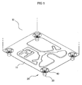
- a household electric appliance provided with a height adjusting apparatus in accordance with an embodiment of the present invention comprises a main body 10 defining an appearance thereof, and a height adjusting apparatus 20 positioned between a base 11 of the main body 10 and an installation surface, for both supporting the main body 10 and adjusting the height of the main body 10.
- the height adjusting apparatus 20 includes support legs 30 positioned between the base 11 of the main body 10 and the installation surface.
- the height adjusting apparatus 20 further includes support members 40 installed at the base 11 to connect the support legs 30 thereto. The height of the main body 10 is adjusted by the support legs 30 and the support members 40.
- the support legs 30 are detachably connected to the support members 40.
- Each of the support members 40 includes a leg connection portion 41 provided with a connection hole 41a to receive the support legs 30.
- Each of the support legs 30 includes a leg portion 31 inserted into the connection hole 41a, and a head portion 32 seated on the leg connection portion 41.
- internal threads are formed on inner circumferences of the connection holes 41a, and external threads are formed on outer circumferences of the leg portions 31 of the support legs 30.
- the support legs 30 when the support legs 30 are rotated in one direction, once the leg portions 31 of the support legs 30 are screwed into the connection holes 41a, the support legs 30 come out of the support member 40 by a designated distance, thereby allowing the main body 10 to have an increased height.
- the support legs 30 when the support legs 30 are rotated in the opposite direction, the support legs 30 enter into the support member 40 by a designated distance, thereby allowing the main body 10 to have a decreased height.
- leg portions 31 of the support legs 30 are prepared to have a designated length, when the support legs 30 are continuously rotated in the direction that the height of the main body 10 is increased, the leg portions 31 of the support legs 30 come out of the connection holes 41a and the support legs 30 are separated from the support members 40. On the other hand, when the support legs 30 are continuously rotated in the direction that the height of the main body 10 is decreased, the head portions 32 of the support legs 30 are seated on the leg connection portions 41 around the connection holes 41a, so that the height of the main body 10 is not further decreased.
- the base 11 further includes through holes 12.
- the through holes 12, having a predetermined size, are positioned at corners of the base 11 of the main body 10.
- the support members 40 provided with the support legs 30 connected thereto are detachably attached to the base 11 so that the through holes 12 are covered with the support members 40.
- the support members 40 are designed such that the heights of the leg connection portions 41 vary, thereby allowing the height of the main body 10 to be adjusted independent of the movement of the support legs 30.
- a base connection portion 42 is formed in an annular shape around the edge of the support member 40, and is provided on each of the support members 40.
- a plurality of holes 13 to screw the support members 40 to the base 11 are positioned on the base connection portions 42 and corresponding portions of the base 11 around the through hole 12. Accordingly, screws 14 are screwed into the holes 13 when the base connection portions 42 of the support members 40 are supported on the external surface of the base 11, so that the holes 13 positioned on the base connection portions 42 coincide with the holes 13 formed through the base 11, thus connecting the support members 40 to the base 11.
- the support members 40 can be connected to the base 11 even when the base connection portions 42 are inverted.
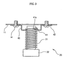
- Each of the support members 40 further includes a protrusion 43 formed integrally with the base connection portion 42, and each of the through holes 12 is positioned such that the protrusion 43 can be inserted into the through hole 12.
- the protrusion 43 protrudes from the support member 40 toward the lower part of the through hole 12.
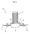
- the protrusion 43 protrudes from the support member 40 toward an upper part of the through hole 12.
- the leg connection portion 41 on which the support leg 30 is seated, is positioned at the end of the protrusion 43.
- the leg connection portions 41 are positioned on the upper surface of the base 11, and the height of the main body 10 is decreased.
- the leg connection portions 41 are positioned on the lower surface of the base 11, and the height of the main body 10 is increased, as is shown in Figure 3.
- the above-described height adjusting apparatus of this embodiment of the present invention adjusts the height of the main body 10 using the support members 40 as well as the support legs 30, thus being effectively employed by household electric appliances requiring the main body 10 having a height in a broad adjustment range.
- the protrusions 43 protrude from the support member 40 toward the upper parts of the through holes 12, and are rotated such that the head portions 32 of the support legs 30 are located within the protrusions 43.
- the height of the main body 10 is adjusted to be decreased so that the leg portions of the support legs 30 are entirely positioned within the main body 10.
- the base connection portions 42 of the support members 40 can be supported on the internal surface of the base 11. But, to easily convert the orientation of the support members 40 after the assembly of the main body 10 of the household electric appliance, or during the use of the household electric appliance, it is preferable that the base connection portions 42 of the support members 40 are supported on the external surface of the base 11.
- an outer diameter of the head portion 32 of the support leg 30 is smaller than an inner diameter of the protrusion 43 of the support member 40.
- an upper portion of the head portion 32 of the support leg 30 is positioned in the protrusion 43 when the protrusion 43 protrudes from the support member 40 toward the upper part of the through holes 12, allowing the distance from the base 11 to the installation surface to be adjusted to less than a length of the head portion 32 of the support leg 30.
- the length of the head portion 32 of the support leg 30 is greater than a length of the protrusion 43 of the support member 40, so that the main body 10 is supported on the installation surface through the support legs 30 even when the height of the main body 10 is maximally decreased.
- the above-described height adjusting apparatus 20 can be applied to general household electric appliances, such as a washing machine, a clothes dryer, a refrigerator, ovens, or other large or small devices for which leveling or adjustment relative to the surface is required. Additionally, the apparatus 20 can be used in non-appliances, such as furniture. Further, the apparatus 20 can be used in legs or supports for a shelving system. But the apparatus 20 can be effectively applied to certain household electric appliances, which are used independently or stacked on other appliances, such as a drum-type washing machine or a drum-type clothes dryer. Hereinafter, a drum-type washing machine and a drum-type clothes dryer, respectively applying the height adjusting appliance 20, will be described in detail, by way of example.
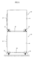
- Figure 5 is a side view of a stack structure of a lower drum-type washing machine and an upper drum-type clothes dryer respectively applying the height adjusting apparatus 20 in accordance with an embodiment of the present invention.
- the conventional drum-type washing machine 50 and drum-type clothes dryer 60 respectively include main bodies 51 and 61, and doors 52 and 62, respectively installed at front surfaces of the main bodies 51 and 61.
- the conventional drum-type washing machine 50 and drum-type clothes dryer 60 can be installed independently, or can be stacked to reduce an installation area thereof.
- the clothes dryer 60 having a comparatively light weight, is stacked on the washing machine 50.
- the height adjusting apparatus 20 is installed on each of bases 53 and 63 of the respective main bodies 51 and 61.
- the height adjusting apparatuses 20 of the drum-type washing machine 50 positioned at the lower part are oriented such that the protrusions 43 are protruded from the support members 40 toward the lower parts of the through holes 12, so that the leg connection portions 41 are positioned on the lower surface of the base 53 and the support legs 30 are maximally extended outwardly from the support members 40.
- the main body 51 of the drum-type washing machine 50 positioned at the lower part has an increased height larger than the length of the support legs 30 using the height adjusting apparatus 20, thereby minimizing an inconvenience that a user bends forward to put the laundry into and take the laundry out of the main body 51.
- the height adjusting apparatus 20 of the drum-type clothes dryer 60 positioned at the upper part, are oriented such that the protrusions 43 protrude from the support members 40 toward the upper parts of the through holes 12, so that the leg connection portions 41 are positioned on the upper surface of the base 63 and the support legs 30 are maximally inserted into the support members 40.
- the main body 61 of the drum-type clothes dryer 60 positioned at the upper part, is separated from an upper surface of the main body 51 of the washing machine 50 by a distance that is less than the length of the head portions 32 of the support legs 30, thereby allowing the user to easily put the laundry into and take the laundry out of the main body 61 without use of a foothold, footstool, or other elevating device.
- the height adjusting apparatus 20 for a household electric appliance in accordance with an embodiment of the present invention is constructed such that the height of the main body is adjusted by the support members 40 as well as the support legs 30, the height adjustment range of the main body 10 of the household electric appliance is highly expanded, thus allowing the height adjusting apparatus 20 to be effectively applied to a drum-type washing machine 50 and a drum-type clothes dryer 60 used independently or in a stacked structure.
- the height adjusting apparatus 20 of this embodiment of the present invention is applied to the drum-type washing machines 50 arranged in a multiple stack structure or the drum-type clothes dryers 60 arranged in a multiple stack structure, the height adjusting apparatus 20 has the same functions and effects.
- the height adjusting apparatus 20 When the height adjusting apparatus 20 is installed at the household electric appliance to adjust the height of the main body 10 so that the maximum distance between the base 11 and the installation surface is greater than the length of the support legs 30, the holes 13 positioned on the base 11 coincide with the holes 13 positioned on the base connection portions 42 of the support members 40.
- the support members 40 are positioned on the base 11 around the through holes 12, such that the protrusions 43 protrude from the support members 40 toward the lower parts of the through holes 12, and the support members 40 are fixed to the base 11 by inserting the screws 14 into the holes 13.
- the leg portions 31 of the support legs 30 are inserted into the connection holes 41a formed through the leg connection portions 41 of the support members 40, thereby allowing the height adjusting apparatus 20 to be completely installed at the household electric appliance.
- the height of the main body 10 may be adjusted by rotating the support legs 30 such that the maximum distance between the base 11 and the installation surface is greater than the length of the support legs 30.
- the support legs 30 are separated from the support members 40, and the support members 40 are separated from the base 11 of the main body 10. Then, the support members 40 are fixed again to the base 11 such that the protrusions 43 protrude from the support members 40 toward the upper parts of the through holes 12.
- the leg portions 31 of the support legs 30 are inserted again into the connection holes 41a formed through the leg connection portions 41 of the support members 40, and in this state the height of the main body 10 may be adjusted by rotating the support legs 30 such that the minimum distance between the base 11 and the installation surface is less than the length of the head portions 32 of the support legs 30.
- embodiments of the present invention provides the height adjusting apparatus and the household electric appliance provided with the apparatus, in which the height of the main body 10 of the household electric appliance is adjusted using both the support members 40 installed at the base 11 and connected to the support legs 30, as well as the support legs 30 positioned between the base 11 of the main body 10 and the installation surface, thereby highly expanding the height adjustment range of the main body 10.
- embodiments of the present invention can be used to adjust a relative distance between adjacent sidewalls, to adjust a horizontal distance.
Landscapes
- Engineering & Computer Science (AREA)
- Textile Engineering (AREA)
- Main Body Construction Of Washing Machines And Laundry Dryers (AREA)
- Detail Structures Of Washing Machines And Dryers (AREA)
- Casings For Electric Apparatus (AREA)
Claims (9)
- Appareil électrique domestique doté d'un dispositif de réglage de la hauteur, l'appareil comprenant:- un corps principal (10);- une base (11) prévue sur le corps principal (10) ; et- un dispositif de réglage de la hauteur (20) qui comprend- au moins une jambe de support (30) pouvant être agencée pour être positionnée entre la base (11) du corps principal (10) et une surface d'installation ; et- au moins un organe de support (40) installé sur la base (11), chaque organe de support (40) comprenant une portion de connexion de jambe (41) recevant la jambe de support (30), et- une protubérance (43) faisant saillie à partir de l'organe de support, la portion de connexion de jambe (41) étant connectée à une extrémité de celle-ci,caractérisé en ce que la base (11) comprend un trou traversant (12) correspondant à une position d'installation de l'organe de support (40), à travers lequel la protubérance (43) est sélectivement insérée ; et en ce que l'organe de support (40) est installé sur la base et peut être réorienté sur la base (11) pour que la protubérance (43) soit de face ou de dos à la base pour faire varier une hauteur de la portion de connexion de jambe (41) par rapport à la surface d'installation.
- Appareil électrique domestique selon la revendication 1, dans lequel la portion de connexion de jambe (41) est positionnée sur l'une parmi une surface interne et une surface externe de la base (11).
- Appareil électrique domestique selon la revendication 2, dans lequel l'organe de support (40) comprend :- une portion de connexion de base (42) supportée sur la base (11) ; et- dans lequel une d'une première ou d'une seconde surface de la portion de connexion de base (42) est sélectivement supportée sur la base (11) de sorte que la portion de connexion de jambe (41) soit positionnée sur une des surfaces interne ou externe de la base.
- Appareil électrique domestique selon la revendication 3, dans lequel la portion de connexion de base (42) est supportée sur la surface externe de la base (11).
- Appareil électrique domestique selon la revendication 3, dans lequel l'organe de support (40) est connecté de manière amovible à la base (11), et la jambe de support (30) est connectée de manière amovible à l'organe de support correspondant(40).
- Appareil électrique domestique selon l'une quelconque des revendications 3 à 5, dans lequel la hauteur du corps principal (10) est réglée par la jambe de support (30).
- Appareil électrique domestique selon la revendication 6, dans lequel :- la portion de connexion de jambe (41) a un trou de connexion (41a) ;- la jambe de support (30) comprend- une portion de jambe (31) insérée dans le trou de connexion (41a), et- une portion de tête (32) siégeant sur la circonférence externe du trou de connexion (41a) ;- une circonférence interne du trou de connexion (41a) à un filetage interne ; et- une circonférence externe de la portion de jambe (31) à un filetage externe pour régler la hauteur du corps principal (10) par la rotation de la jambe de support (30).
- Appareil électrique domestique selon la revendication 7, dans lequel un diamètre externe de la portion de tête (32) est inférieur à un diamètre interne de la protubérance (43).
- Appareil électrique domestique selon la revendication 7, dans lequel une longueur de la portion de tête (32) est supérieure à une longueur de la protubérance (43).
Applications Claiming Priority (2)
| Application Number | Priority Date | Filing Date | Title |
|---|---|---|---|
| KR2003081248 | 2003-11-17 | ||
| KR1020030081248A KR20050047426A (ko) | 2003-11-17 | 2003-11-17 | 가전제품용 높이조절장치 및 이를 구비한 가전제품 |
Publications (2)
| Publication Number | Publication Date |
|---|---|
| EP1530925A1 EP1530925A1 (fr) | 2005-05-18 |
| EP1530925B1 true EP1530925B1 (fr) | 2007-05-16 |
Family
ID=34431785
Family Applications (1)
| Application Number | Title | Priority Date | Filing Date |
|---|---|---|---|
| EP04254734A Expired - Lifetime EP1530925B1 (fr) | 2003-11-17 | 2004-08-06 | Dispositif d'ajustage de la hauteur et machine domestique électrique équipée d'un tel dispositif |
Country Status (7)
| Country | Link |
|---|---|
| US (1) | US7588218B2 (fr) |
| EP (1) | EP1530925B1 (fr) |
| JP (1) | JP4125703B2 (fr) |
| KR (1) | KR20050047426A (fr) |
| CN (1) | CN1321551C (fr) |
| DE (1) | DE602004006476T2 (fr) |
| ES (1) | ES2289443T3 (fr) |
Families Citing this family (22)
| Publication number | Priority date | Publication date | Assignee | Title |
|---|---|---|---|---|
| US7958651B2 (en) * | 2006-05-19 | 2011-06-14 | Maniha Allan M | Clothes dryer rake |
| PL1950338T3 (pl) * | 2007-01-25 | 2011-08-31 | Electrolux Home Products Corp Nv | Kolumnowy zestaw urządzeń wykorzystywanych w gospodarstwie domowym |
| ITMC20070037A1 (it) * | 2007-02-28 | 2008-09-01 | V I C Viterie Italia Centrale Srl | Sistema di montaggio di piedini regolabili in altezza su macchine lavabiancheria e simili. |
| DE102007030073B3 (de) * | 2007-06-29 | 2008-11-27 | BSH Bosch und Siemens Hausgeräte GmbH | Haushaltsgerät mit höhenverstellbaren Fußelementen |
| BRPI0910071A2 (pt) * | 2008-04-04 | 2015-12-29 | Electrolux Ab | membro de trempe modular, e, sistema de trempe |
| US8152117B2 (en) * | 2008-12-30 | 2012-04-10 | Paul R. Gain | Adjustable bushing |
| CN102418733B (zh) * | 2010-09-28 | 2013-08-07 | 富泰华工业(深圳)有限公司 | 高度调整机构及使用其对电子装置进行组装的组装方法 |
| CN102541208B (zh) * | 2010-12-28 | 2014-12-03 | 南通新业电子有限公司 | 机箱 |
| CN103037650B (zh) * | 2011-09-28 | 2015-06-03 | 纬创资通股份有限公司 | 用于电子装置的支撑组合件 |
| KR102376043B1 (ko) * | 2015-07-14 | 2022-03-18 | 엘지전자 주식회사 | 식기세척기 |
| GB201611656D0 (en) * | 2016-07-04 | 2016-08-17 | Howden Joinery Ltd | Adjustable leg |
| WO2018024574A1 (fr) * | 2016-08-05 | 2018-02-08 | Arcelik Anonim Sirketi | Appareil ménager à réglage de hauteur et installation améliorés |
| US20180055226A1 (en) * | 2016-09-01 | 2018-03-01 | Eric Prince | Adjustable stand for household appliance |
| CN106263706A (zh) * | 2016-10-27 | 2017-01-04 | 苏州市淞舜五金有限公司 | 一种简易升降柜腿 |
| CN106263705A (zh) * | 2016-10-27 | 2017-01-04 | 苏州市淞舜五金有限公司 | 一种螺纹升降柜腿 |
| US10206511B2 (en) * | 2016-11-23 | 2019-02-19 | Robert F. Peters | Universal chair leveler |
| US20180199452A1 (en) * | 2017-01-12 | 2018-07-12 | Hubbell Incorporated | Floor box stands and electrical box assemblies |
| US9970680B1 (en) * | 2017-08-07 | 2018-05-15 | Sarkis Shmavonovich Babayan | Leveling base for water heater |
| US11357319B1 (en) * | 2019-02-19 | 2022-06-14 | Noble House Home Furnishings, Llc | Table and table assembly |
| USD996163S1 (en) * | 2020-08-27 | 2023-08-22 | Marcy Enterprises, Inc. | Leveler table |
| US11478073B2 (en) * | 2020-10-20 | 2022-10-25 | Exemplis Llc | Table with removable legs |
| CN116946570A (zh) * | 2022-04-15 | 2023-10-27 | 重庆海尔滚筒洗衣机有限公司 | 一种用于设备叠放的固定组件及叠放设备组合 |
Family Cites Families (15)
| Publication number | Priority date | Publication date | Assignee | Title |
|---|---|---|---|---|
| US1886112A (en) * | 1932-01-14 | 1932-11-01 | Joseph A Luarde | Adjustable cushion support |
| US2327050A (en) * | 1940-03-20 | 1943-08-17 | Kotler Paul | Leveling device for shuffleboard tables |
| US4632356A (en) * | 1984-04-19 | 1986-12-30 | Erich Munz | Vertically adjustable shock-absorbing mounting device |
| US4752056A (en) * | 1987-05-14 | 1988-06-21 | Culbertson Lonnie W | Floor protector for appliance leveling leg |
| DE4203515C1 (en) * | 1992-02-07 | 1993-04-15 | Paul Henke Gmbh + Co Kg, 4972 Loehne, De | Furniture socket height adjuster - has stop for spacing tube in guide bush, with tube contg. radially resetting section |
| US5641139A (en) * | 1994-06-28 | 1997-06-24 | S & M Furniture Mgf., Inc. | Furniture leg with anchoring means |
| DE29513826U1 (de) * | 1995-08-29 | 1995-10-26 | Maaß, Harald, 32689 Kalletal | Möbelfuß |
| KR100198007B1 (ko) * | 1995-10-31 | 1999-06-15 | 전주범 | 냉장고의 수평조절장치 |
| US5688287A (en) * | 1996-07-25 | 1997-11-18 | Rid-Gid Products, Inc. | Leg for box springs |
| US5967472A (en) * | 1997-04-03 | 1999-10-19 | Bsh Bosch Und Siemens Hausgeraete Gmbh | Height-adjusting device for an adjusting foot of a household appliance |
| US5881979A (en) * | 1997-06-04 | 1999-03-16 | Knoll, Inc. | Telescoping leveler |
| KR100271737B1 (ko) | 1997-12-11 | 2000-11-15 | 구자홍 | 드럼세탁기의 다리높이 조절장치 |
| US6407351B1 (en) * | 1999-09-29 | 2002-06-18 | Premark Feg L.L.C. | Thread covering assembly for adjustable support feet and the like |
| KR20020061387A (ko) * | 2001-01-16 | 2002-07-24 | 박혁구 | 유치원 어린이용 책상 |
| US6533238B2 (en) * | 2001-07-11 | 2003-03-18 | Maytag Corporation | Versatile anti-tip bracket for an appliance |
-
2003
- 2003-11-17 KR KR1020030081248A patent/KR20050047426A/ko not_active Ceased
-
2004
- 2004-07-26 US US10/898,162 patent/US7588218B2/en not_active Expired - Lifetime
- 2004-08-06 EP EP04254734A patent/EP1530925B1/fr not_active Expired - Lifetime
- 2004-08-06 CN CNB2004100563493A patent/CN1321551C/zh not_active Expired - Lifetime
- 2004-08-06 ES ES04254734T patent/ES2289443T3/es not_active Expired - Lifetime
- 2004-08-06 DE DE602004006476T patent/DE602004006476T2/de not_active Expired - Lifetime
- 2004-09-10 JP JP2004264305A patent/JP4125703B2/ja not_active Expired - Fee Related
Also Published As
| Publication number | Publication date |
|---|---|
| US20050103966A1 (en) | 2005-05-19 |
| CN1620233A (zh) | 2005-05-25 |
| ES2289443T3 (es) | 2008-02-01 |
| KR20050047426A (ko) | 2005-05-20 |
| EP1530925A1 (fr) | 2005-05-18 |
| JP4125703B2 (ja) | 2008-07-30 |
| DE602004006476T2 (de) | 2008-01-17 |
| JP2005144146A (ja) | 2005-06-09 |
| CN1321551C (zh) | 2007-06-13 |
| US7588218B2 (en) | 2009-09-15 |
| DE602004006476D1 (de) | 2007-06-28 |
Similar Documents
| Publication | Publication Date | Title |
|---|---|---|
| EP1530925B1 (fr) | Dispositif d'ajustage de la hauteur et machine domestique électrique équipée d'un tel dispositif | |
| US5697586A (en) | Appliance mounting assembly | |
| US20090139273A1 (en) | Laundry machine | |
| US20130228540A1 (en) | Laundry drying rack | |
| EP2189566B1 (fr) | Machine de traitement du linge | |
| EP1757724B1 (fr) | Machine à laver avec support d'amortisseur. | |
| CN110230835B (zh) | 一种电暖器 | |
| KR20060009082A (ko) | 세탁장치의 수평 조절용 받침대 | |
| KR200453110Y1 (ko) | 벽면 설치형 빨래 건조 조립체 | |
| KR200220467Y1 (ko) | 다림질 판 | |
| KR200173946Y1 (ko) | 포스트 신축 조절장치 | |
| KR102104895B1 (ko) | 지지장치 및 지지장치가 구비된 의류처리장치 | |
| KR200219925Y1 (ko) | 높이조절 빨래판 | |
| KR200167663Y1 (ko) | 높이조절 및 절첩식 다리미판 | |
| KR101008621B1 (ko) | 가전제품용 레그 어셈블리 | |
| KR101236103B1 (ko) | 식기 세척기의 수평 조절 장치 | |
| KR20030067652A (ko) | 확장성을 갖는 식기건조대 겸용 봉선반 | |
| KR20170136204A (ko) | 사용편의성이 향상된 빨래건조대 | |
| KR100290586B1 (ko) | 의복걸이대 | |
| KR200261063Y1 (ko) | 보조다리미판이 구비된 다리미판 | |
| KR20020044271A (ko) | 드럼세탁기의 밸런싱 레그 구조 | |
| CN120813737A (zh) | 配备有调平系统的家用器具 | |
| KR20180124609A (ko) | 슬라이드 선반 | |
| KR19990015569U (ko) | 냉장고의 지지장치 | |
| KR20000005547U (ko) | 휴대용 테이블 |
Legal Events
| Date | Code | Title | Description |
|---|---|---|---|
| PUAI | Public reference made under article 153(3) epc to a published international application that has entered the european phase |
Free format text: ORIGINAL CODE: 0009012 |
|
| AK | Designated contracting states |
Kind code of ref document: A1 Designated state(s): AT BE BG CH CY CZ DE DK EE ES FI FR GB GR HU IE IT LI LU MC NL PL PT RO SE SI SK TR |
|
| AX | Request for extension of the european patent |
Extension state: AL HR LT LV MK |
|
| 17P | Request for examination filed |
Effective date: 20050706 |
|
| AKX | Designation fees paid |
Designated state(s): DE ES FR GB IT |
|
| GRAP | Despatch of communication of intention to grant a patent |
Free format text: ORIGINAL CODE: EPIDOSNIGR1 |
|
| GRAS | Grant fee paid |
Free format text: ORIGINAL CODE: EPIDOSNIGR3 |
|
| GRAA | (expected) grant |
Free format text: ORIGINAL CODE: 0009210 |
|
| AK | Designated contracting states |
Kind code of ref document: B1 Designated state(s): DE ES FR GB IT |
|
| REG | Reference to a national code |
Ref country code: GB Ref legal event code: FG4D |
|
| REF | Corresponds to: |
Ref document number: 602004006476 Country of ref document: DE Date of ref document: 20070628 Kind code of ref document: P |
|
| PGFP | Annual fee paid to national office [announced via postgrant information from national office to epo] |
Ref country code: ES Payment date: 20070927 Year of fee payment: 4 |
|
| ET | Fr: translation filed | ||
| REG | Reference to a national code |
Ref country code: ES Ref legal event code: FG2A Ref document number: 2289443 Country of ref document: ES Kind code of ref document: T3 |
|
| PLBE | No opposition filed within time limit |
Free format text: ORIGINAL CODE: 0009261 |
|
| STAA | Information on the status of an ep patent application or granted ep patent |
Free format text: STATUS: NO OPPOSITION FILED WITHIN TIME LIMIT |
|
| 26N | No opposition filed |
Effective date: 20080219 |
|
| REG | Reference to a national code |
Ref country code: ES Ref legal event code: FD2A Effective date: 20080807 |
|
| PG25 | Lapsed in a contracting state [announced via postgrant information from national office to epo] |
Ref country code: ES Free format text: LAPSE BECAUSE OF NON-PAYMENT OF DUE FEES Effective date: 20080807 |
|
| REG | Reference to a national code |
Ref country code: FR Ref legal event code: PLFP Year of fee payment: 13 |
|
| REG | Reference to a national code |
Ref country code: FR Ref legal event code: PLFP Year of fee payment: 14 |
|
| REG | Reference to a national code |
Ref country code: DE Ref legal event code: R082 Ref document number: 602004006476 Country of ref document: DE Representative=s name: WUNDERLICH & HEIM PATENTANWAELTE PARTNERSCHAFT, DE |
|
| REG | Reference to a national code |
Ref country code: FR Ref legal event code: PLFP Year of fee payment: 15 |
|
| PGFP | Annual fee paid to national office [announced via postgrant information from national office to epo] |
Ref country code: IT Payment date: 20180814 Year of fee payment: 10 Ref country code: FR Payment date: 20180727 Year of fee payment: 15 |
|
| PGFP | Annual fee paid to national office [announced via postgrant information from national office to epo] |
Ref country code: GB Payment date: 20180725 Year of fee payment: 15 |
|
| GBPC | Gb: european patent ceased through non-payment of renewal fee |
Effective date: 20190806 |
|
| PG25 | Lapsed in a contracting state [announced via postgrant information from national office to epo] |
Ref country code: FR Free format text: LAPSE BECAUSE OF NON-PAYMENT OF DUE FEES Effective date: 20190831 |
|
| PG25 | Lapsed in a contracting state [announced via postgrant information from national office to epo] |
Ref country code: GB Free format text: LAPSE BECAUSE OF NON-PAYMENT OF DUE FEES Effective date: 20190806 Ref country code: IT Free format text: LAPSE BECAUSE OF NON-PAYMENT OF DUE FEES Effective date: 20190806 |
|
| PGFP | Annual fee paid to national office [announced via postgrant information from national office to epo] |
Ref country code: DE Payment date: 20230720 Year of fee payment: 20 |
|
| REG | Reference to a national code |
Ref country code: DE Ref legal event code: R071 Ref document number: 602004006476 Country of ref document: DE |