EP1530850B1 - Store and forward switch device, system and method - Google Patents
Store and forward switch device, system and method Download PDFInfo
- Publication number
- EP1530850B1 EP1530850B1 EP03793243A EP03793243A EP1530850B1 EP 1530850 B1 EP1530850 B1 EP 1530850B1 EP 03793243 A EP03793243 A EP 03793243A EP 03793243 A EP03793243 A EP 03793243A EP 1530850 B1 EP1530850 B1 EP 1530850B1
- Authority
- EP
- European Patent Office
- Prior art keywords
- data packet
- switch
- port
- received data
- egress port
- Prior art date
- Legal status (The legal status is an assumption and is not a legal conclusion. Google has not performed a legal analysis and makes no representation as to the accuracy of the status listed.)
- Expired - Lifetime
Links
- 238000000034 method Methods 0.000 title claims abstract description 75
- 239000004744 fabric Substances 0.000 claims abstract description 16
- 238000012545 processing Methods 0.000 claims description 55
- 238000011144 upstream manufacturing Methods 0.000 claims description 51
- 230000004044 response Effects 0.000 claims description 26
- 230000000977 initiatory effect Effects 0.000 claims 1
- 230000005540 biological transmission Effects 0.000 description 24
- 230000008569 process Effects 0.000 description 23
- 238000010586 diagram Methods 0.000 description 16
- 230000002093 peripheral effect Effects 0.000 description 12
- 230000006870 function Effects 0.000 description 11
- 238000004891 communication Methods 0.000 description 10
- 229910003460 diamond Inorganic materials 0.000 description 6
- 239000010432 diamond Substances 0.000 description 6
- 239000000872 buffer Substances 0.000 description 2
- 238000006243 chemical reaction Methods 0.000 description 2
- 230000008878 coupling Effects 0.000 description 2
- 238000010168 coupling process Methods 0.000 description 2
- 238000005859 coupling reaction Methods 0.000 description 2
- 230000014509 gene expression Effects 0.000 description 2
- 238000013507 mapping Methods 0.000 description 2
- 238000012986 modification Methods 0.000 description 2
- 230000004048 modification Effects 0.000 description 2
- 238000010200 validation analysis Methods 0.000 description 2
- 230000015572 biosynthetic process Effects 0.000 description 1
- 238000004364 calculation method Methods 0.000 description 1
- 125000004122 cyclic group Chemical group 0.000 description 1
- 238000001514 detection method Methods 0.000 description 1
- 238000013073 enabling process Methods 0.000 description 1
- 230000003993 interaction Effects 0.000 description 1
- 230000003287 optical effect Effects 0.000 description 1
- 239000004065 semiconductor Substances 0.000 description 1
Images


Classifications
-
- H—ELECTRICITY
- H04—ELECTRIC COMMUNICATION TECHNIQUE
- H04L—TRANSMISSION OF DIGITAL INFORMATION, e.g. TELEGRAPHIC COMMUNICATION
- H04L49/00—Packet switching elements
- H04L49/25—Routing or path finding in a switch fabric
- H04L49/252—Store and forward routing
-
- H—ELECTRICITY
- H04—ELECTRIC COMMUNICATION TECHNIQUE
- H04L—TRANSMISSION OF DIGITAL INFORMATION, e.g. TELEGRAPHIC COMMUNICATION
- H04L49/00—Packet switching elements
- H04L49/25—Routing or path finding in a switch fabric
- H04L49/253—Routing or path finding in a switch fabric using establishment or release of connections between ports
-
- H—ELECTRICITY
- H04—ELECTRIC COMMUNICATION TECHNIQUE
- H04L—TRANSMISSION OF DIGITAL INFORMATION, e.g. TELEGRAPHIC COMMUNICATION
- H04L49/00—Packet switching elements
- H04L49/30—Peripheral units, e.g. input or output ports
- H04L49/3009—Header conversion, routing tables or routing tags
-
- H—ELECTRICITY
- H04—ELECTRIC COMMUNICATION TECHNIQUE
- H04L—TRANSMISSION OF DIGITAL INFORMATION, e.g. TELEGRAPHIC COMMUNICATION
- H04L49/00—Packet switching elements
- H04L49/55—Prevention, detection or correction of errors
- H04L49/555—Error detection
Landscapes
- Engineering & Computer Science (AREA)
- Computer Networks & Wireless Communication (AREA)
- Signal Processing (AREA)
- Data Exchanges In Wide-Area Networks (AREA)
- Supplying Of Containers To The Packaging Station (AREA)
- Communication Control (AREA)
Abstract
Description
- The subject matter disclosed herein relates to copending
U.S. Patent Appl. Nos. 10/005,895, filed on November 2, 2001 ,09/997,441, filed on November 28, 2001 10/040,702, filed on December 28, 2001 10/041,040, filed on December 28, 2001 - The subject matter disclosed herein relates to the transmission of data packets. In particular, the subject matter disclosed herein relates to forwarding data packets from source devices to destination devices.
- Processing platforms typically comprise a host processing system, peripheral devices and an I/O system that enables communication between processes hosted on the host processing system and the peripheral devices. Such an I/O system is typically formed according to one or more standard I/O architectures such as, for example, the peripheral components interconnect (PCI) architecture according to the PCI Local Bus Specification, Rev. 2.2, December 18,1998, or PCI Express Base Specification, Rev. 1.0, July 16, 2002, promoted by the PCI Special Interest Group.
- A communication system may transmit messages or data packets between devices coupled by links according to a data link layer protocol. In such a system, a device may transmit messages or data packets to any of a plurality of other devices through a switch. The switch will typically receive messages or data packets from a source device at an ingress port and forward the messages or data packets to a destination device through an egress port. Prior to forwarding a received message or data packet, however, the switch typically performs a checksum operation on a portion of the received message or data packet to ensure the integrity of the received packet. Such system is disclosed, for example, in document
US-B1-6208645 (James David et Al), 27 March 2001 . Such a checksum operation typically introduces latencies in the process of forwarding the message or data packet from the source device to the destination device. - Non-limiting and non-exhaustive embodiments of the present invention will be described with reference to the following figures, wherein like reference numerals refer to like parts throughout the various figures unless otherwise specified.
-
Figure 1 shows a schematic diagram of a processing platform according to an embodiment of the present invention. -
Figure 2 shows a schematic diagram of a processing platform according to an alternative embodiment of the present invention. -
Figure 3 shows a schematic diagram of a portion of a switch according to embodiments of the present invention shown inFigures 1 and2 . -
Figure 4 shows a format of a data packet according to an embodiment of the switch shown inFigure 3 . -
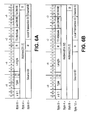
Figures 5A and5B show a flow diagram illustrating a process to forward a data packet from an ingress port to an egress port according to an embodiment of the switch shown inFigure 3 . -
Figures 6A through 6E show formats for a packet header received at ingress port according to an alternative embodiment of the switch shown inFigure 3 . -
Figure 7 shows a flow diagram illustrating a process to forward a data packet from an ingress port to an egress port according to an embodiment of the data packet headers shown inFigures 6A through 6E . -
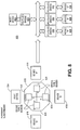
Figure 8 shows a schematic diagram mapping of a multi-port switch to a representation of a PCI bus structure according to an embodiment of the switch shown inFigures 3 . -
Figure 9 shows a schematic diagram illustrating the formation of a routing table from a combination of decoded address ranges for transmitting downstream messages and inversely decoding for upstream routing according to an embodiment of the multi-port switch shown inFigure 8 . -
Figure 10 shows a flow diagram illustrating an enumeration process according to an embodiment of the multi-port switch shown inFigure 8 . - Reference throughout this specification to "one embodiment" or "an embodiment" means that a particular feature, structure, or characteristic described in connection with the embodiment is included in at least one embodiment of the present invention. Thus, the appearances of the phrase "in one embodiment" or "an embodiment" in various places throughout this specification are not necessarily all referring to the same embodiment. Furthermore, the particular features, structures, or characteristics may be combined in one or more embodiments.
- "Machine-readable" instructions as referred to herein relates to expressions which may be understood by one or more machines for performing one or more logical operations. For example, machine-readable instructions may comprise instructions which are interpretable by a processor compiler for executing one or more operations on one or more data objects. However, this is merely an example of machine-readable instructions and embodiments of the present invention are not limited in this respect.
- "Machine-readable medium" as referred to herein relates to media capable of maintaining expressions which are perceivable by one or more machines. For example, a machine readable medium may comprise one or more storage devices for storing data or machine-readable instructions. Such storage devices may comprise optical, magnetic or semiconductor media. However, these are merely examples of a machine-readable medium and embodiments of the present invention are not limited in this respect.
- "Logic" as referred to herein relates to structure for performing one or more logical operations. For example, logic may comprise circuitry which provides one or more output signals based upon one or more input signals. Such circuitry may comprise a finite state machine which receives a digital input and provides a digital output, or circuitry which provides one or more analog output signals in response to one or more analog input signals. Also, logic may comprise machine-executable instructions stored in a machine-readable medium in combination with processing circuitry to execute such machine-executable instructions. However, these are merely examples of structures which may provide logic and embodiments of the present invention are not limited in these respects.
- A "processing system" as discussed herein relates to a combination of hardware and software resources for accomplishing computational tasks. However, this is merely an example of a processing system and embodiments of the present invention are not limited in this respect. A "host processing system" as referred to herein relates to a processing system which may be adapted to communicate with a "peripheral device." For example, a peripheral device may provide inputs to or receive outputs from an application process hosted on the host processing system. However, these are merely examples of a host processing system and peripheral device, and embodiments of the present invention are not limited in these respects.
- A "data bus" as referred to herein relates to circuitry for transmitting data between devices. For example, a data bus may transmit data between a host processing system and a peripheral device. However, this is merely an example and embodiments of the present invention are not limited in this respect. A "bus transaction" as referred to herein relates to an interaction between devices coupled in a bus structure wherein one device transmits data addressed to the other device through the bus structure.
- A "port" as referred to herein relates to circuitry to transmit data to or receive data from a transmission medium. For example, a port may comprise circuitry to transmit data to or receive data from a transmission medium according to a data transmission protocol. However, this is merely an example of a port and embodiments of the present invention are not limited in this respect.
- An "ingress" port as referred to herein relates to a port to receive data from a transmission medium according to a data transmission protocol. An "egress" port as referred to herein relates to a port to transmit data through a transmission medium toward a destination. However, these are merely examples of an ingress and egress port, and embodiments of the present invention are not limited in these respects.
- A "data packet" as referred to herein relates to a unit of data that may be transmitted to a destination according to a data transmission protocol. A data packet may comprise a "header" portion and a "payload" portion. The payload portion may comprise content data that is to be processed by a destination device in support of an application. The header portion may comprise control information such as, for example, "destination information." However, this is merely an example of a data packet and embodiments of the present invention are not limited in this respect.
- An egress port may be associated with a "transmit queue" to store data packets to transmit to a transmission medium through the egress port. A transmit queue may be formed from a memory to sequentially store data formatted for transmission over the transmission medium according to a data transmission protocol. Data packets in a transmit queue may be transmitted through an egress port according to ordering rules. However, this is merely an example of a transmit queue and embodiments of the present invention are not limited in this respect.
- A "switch" as referred to herein relates to circuitry and logic to forward received data to one or more destinations. For example, a switch may comprise a plurality of ports and logic to forward data received on an ingress port to an egress port based upon destination information associated with the received data. However, this is merely an example of a switch and embodiments of the present invention are not limited in this respect.
- A "link" as referred to herein relates to circuitry to transmit data between devices. A serial link may provide point to point communication between two devices in either unidirectionally or bi-directionally. Being limited to transmitting data between two points, a serial link may transmit data between the devices independently of address information. However, these are merely examples of a serial link and embodiments of the present invention are not limited in this respect.
- "Routing information" as referred to herein relates to data associating destination addresses with physical destinations. For example, a "routing table" or "look up table" may comprise routing information to associate destination information in a data packet with a physical destination (e.g., a port of a switch or device coupled to a port of a switch). However, these are merely examples of routing information, a routing table and look up table, and embodiments of the present invention are not limited in these respects.
- A switch may comprise a "switch fabric" providing circuitry and logic to forward data between ports. For example, a switch fabric may comprise logic to forward a data packet received on an ingress port to an egress port in response to destination information associated with the egress port. A switch may also comprise a "forwarding circuit" to initiate the forwarding of a received data packet through a switch fabric to an egress port in based upon destination information. For example, a forwarding circuit may associated the destination information with a particular egress port and initiate the forwarding of the received data packet through the switch fabric to the particular egress port. However, these are merely examples of a switch fabric and a forwarding circuit, and embodiments of the present invention are not limited in these respects.
- An "enumeration procedure" as referred to herein relates to a process controlled by a processing system to allocate resources enabling communication between processes hosted on the processing system and devices coupled to an I/O system. For example, an enumeration process may allocate data buffers in a system memory of a processing system for transmitting data to or receiving data from devices coupled to an I/O system. Also, an enumeration procedure may also initialize device drivers on the processing system corresponding with devices coupled to the I/O system. However, these are merely examples of an enumeration procedure and embodiments of the present invention are not limited in these respects.
- A "configuration transaction" as referred to herein relates to an event in an enumeration procedure to allocate resources to a device coupled to a data bus or allocate resources to a device function. A configuration transaction may provide information to a processing system identifying a device or device function to enable allocation of resources to the device or device function. However, this is merely an example of a configuration transaction and embodiments of the present invention are not limited in this respect.
- An enumeration procedure may initiate a configuration transaction by transmitting a "configuration request" addressed to a device or device function. For example, an enumeration procedure may initiate a bus transaction addressed to a targeted device or device function to initiate a configuration transaction to allocate resources to communicate with the targeted device or device function. However this is merely an example of a configuration request and embodiments of the present invention are not limited in this respect.
- "Configuration header" as referred to herein relates to data provided by a device in response to a configuration request. For example, a device may provide a configuration header as formatted data comprising data fields with information identifying the device and/or resource requirements of one or more functions of the device in response to a request. However, this is merely an example of a configuration header and embodiments of the present invention are not limited in this respect.
- A "system bus" as referred to herein relates to a data bus in a processing system coupling hardware resources of a processing system. For example, a system bus may comprise a data bus to couple a central processing unit (CPU) and main memory of a processing system. However, this is merely an example of a system bus and embodiments of the present invention are not limited in this respect.
- A "bridge" as referred to herein relates to circuitry or logic coupled between a data bus and one or more devices to enable transmission of data between the data bus and the devices. For example, a bridge may enable devices to communicate with a data bus according to a protocol native to the data bus. However, this is merely an example of a bridge and embodiments of the present invention are not limited in this respect.
- A bridge may be coupled to a processing system through a "primary bus." Such a bridge may also be coupled to a "secondary bus" to transmit data between the bridge and devices coupled to the secondary bus. Accordingly, the bridge may transmit data from devices coupled to the secondary bus toward the processing system through the primary bus. Similarly, the bridge may transmit data received from the processing system on the primary bus to devices coupled to the secondary bus. However, these are merely examples of primary and secondary busses coupled to a bridge, and embodiments of the present invention are not limited in these respects.
- A "host bridge" as referred to herein relates to a bridge coupled between a system bus and an I/O system. For example, a host bridge may enable communication between a hardware resources of a processing system coupled to a system bus and one or more devices coupled to a hub or second data bus. However, this is merely an example of a host bridge and embodiments of the present invention are not limited in this respect.
- A "root device" as referred to herein relates to a device to transmit data between a processing system and an input/output (I/O) system. Such a root device may comprise hub circuitry coupled to a system bus of a processing system to transmit data between processes hosted on the processing system and devices coupled to an I/O system. Also, a root device may comprise a host bridge coupling such a system bus to I/O devices. However, this is merely an example of a root device and embodiments of the present invention are not limited in this respect.
- A switch may be coupled to a processing system through a root device at an "upstream port" and coupled to other devices through one or more "downstream ports" to transmit data between the other devices and the processing system. Such a switch may also transmit data between the other devices through respective downstream ports. However, these are merely examples of an upstream port and a downstream port, and embodiments of the present invention are not limited in these respects.
- A "cyclic redundancy code" (CRC) as referred to herein relates to a set of bits combined with digital data in a data transmission message. At a receiving point for the data transmission message, a predefined "checksum" operation may be performed on a CRC to indicate the reliability of digital data in a received data transmission message. However, this is merely an example of a CRC and a checksum operation to validate a data transmission from a CRC, and embodiments of the present invention are not limited in these respects.
- Briefly, an embodiment of the present invention is directed to a switch comprising a plurality of ports and a forwarding circuit. The forwarding circuit may commence forwarding data packets from an ingress port through a switch fabric to a transmit queue of an egress port prior to completion of a checksum operation. However, this is merely an example embodiment and other embodiments of the present invention are not limited in these respects.
-
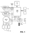
Figure 1 shows a schematic diagram of a processing platform according to an embodiment of the present invention. ACPU 2 andsystem memory 6 are coupled to communicate with peripheral devices throughcore logic 4 providing a root device. Thecore logic 4 may comprise a memory bridge or a memory controller hub (MCH) made by Intel Corporation. However, this is merely an example of a root device and embodiments of the present invention are not limited in this respect. Peripheral devices coupled to thecore logic 4 may include, for example, one ormore communication ports 8, one or more processing bridges 12 (e.g., coupled to input/output (I/O) devices such as a storage processor), an I/O controller hub 14 and aswitch 10. In the illustrated embodiment, the I/O hub controller 14 may also be coupled to devices adapted to communicate with processes hosted on theCPU 2 andsystem memory 6 according to a device protocol such as, for example, a Universal Serial Bus protocol or peripheral components interconnect protocol (PCI) (e.g., according to the PCI Local Bus Specification, Rev. 2.2, December 18, 1998, PCI Special Interest Group, hereinafter the "PCI Local Bus Specification"). Additionally, eachswitch 10 may be coupled to one ormore devices 18. However, this is merely an example of a processing platform and embodiments of the present invention are not limited in this respect. - Each
switch 10 may comprise an upstream port coupled to thecore logic 4 and a plurality of downstream ports coupled todevices 18. According to an embodiment, theswitch 10 may facilitate upstream and downstream communication between adevice 18 and thecore logic 4 through the upstream port. Theswitch 10 may also facilitate direct peer-to-peer communication betweendevices 18 through corresponding downstream ports independently of thecore logic 4. Theswitch 10 may receive data from thecore logic 4 ordevices 18 in a data message or data packet format indicating a destination. Accordingly, theswitch 10 may comprise logic to determine an egress port for such a message or data packet based upon destination data associated with the data message or data packet. However, this is merely an embodiment of a switch as implemented in a processing platform and embodiments of the present invention are not limited in this respect. - According to an embodiment, destination data may comprise any data that may be associated with an egress port of the
switch 10. For example, such destination data may comprise a information identifying a bus segment (e.g., bus number) or serial link for a configuration request packet or split completion packet. Also, destination data in a data message or data packet may comprise a memory map address as part of a non-configuration request packet. However, these are merely examples of destination data and embodiments of the present invention are not limited in these respects. - According to an embodiment, the
devices 18 may comprise any one of several I/O devices such as, for example, an Ethernet controller coupled to a network, a small computer system interface (SCSI), a Serial ATA interface, a Fibrechannel interface or graphics controller interface. However, these are merely examples of devices which may be coupled to a downstream port of a switch and embodiments of the present invention are not limited in this respect. - According to an embodiment, the
CPU 2 may execute one or more procedures to initialize the processing platform to enable processes hosted on theCPU 2 andsystem memory 6 to communicate with peripheral devices. For example, theCPU 2 may execute instructions stored in a non-volatile memory (not shown) as part of a basic I/O system (BIOS). Such instructions may be loaded to thesystem memory 6 and executed in response to a system reset event. Such BIOS instructions may initiate or control one or more enumeration processes to allocate resources to processes (e.g., initializing data bus drivers and device drivers) to communicate with corresponding data buses and devices by, for example, defining buffers in thesystem memory 6. However, this is merely an example of how a processing system may execute processes to initialize a processing platform and embodiments of the present invention are not limited in this respect. - In the illustrated embodiment, the
switches 10 anddevices 18 may be adapted to appear to the core logic 4 (and processes hosted on theCPU 2 and system memory 6) as a PCI devices as defined in the PCI Express Base Specification, Rev. 1.0,Julyt 16, 2002 (hereinafter the "PCI Express Specification"). In this embodiment, an enumeration procedure may allocate resources at the processing platform to communicate with theswitch 10 as a "switch" device as provided in section 1.3.3 of the PCI Express Specification anddevices 18 as "endpoints" as provided in section 1.3.2 of the PCI Express Specification. However, this is merely an example of how a processing system may be adapted to communicate with a switch and devices coupled to ports of the switch, and embodiments of the present invention are not limited in this respect. - According to an embodiment, the
CPU 2 may execute an enumeration procedure to, among other things, allocate resources to communicate with thedevices 18 coupled to downstream ports of aswitch 10 through the upstream port of theswitch 10 and establish routing information to forward data messages or data packets from the upstream ports to the downstream ports. Theswitch 10 may then comprise logic to transmit data from a source downstream port to a destination downstream port based upon the collective routing information that was established for forwarding data messages or data packets from the upstream port to the destination downstream port. However, this is merely an example of how a switch may forward a data message or data packet from a source downstream port to a destination downstream port and embodiments of the present invention are not limited in this respect. -
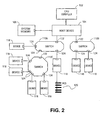
Figure 2 shows a schematic diagram of a processing platform according to an alternative embodiment of the present invention. ACPU complex 102 andsystem memory 108 may comprise a processing system (e.g., comprising one or more CPUs and system memory) which communicates with peripheral devices through aroot device 104. Switches 110 each comprise anupstream port 122 and a plurality ofdownstream ports 124 coupled todevices 118. Adevice 118 may define an endpoint comprising circuitry to transmit data to or receive data from points on the processing platform. Adevice 118 may also define a bridge to a data bus of alegacy PCI system 120 according to the PCI Local Bus specification. - In the illustrated embodiment, a
device 118 coupled to adownstream port 124 of a switch 110 may communicate with processes hosted on theCPU complex 102 through the upstream 122 of the switch 110. TheCPU complex 102 may execute an enumeration procedure to configure the switches 110 and resources at theCPU complex 102 to enabling communication with thedevices 118. Such an enumeration procedure may comprise a procedure to enumerate the switches 110 anddevices 118 as a "switch" or "endpoint" device as provided inSection 7 of the PCI Express Specification. - In the illustrated embodiment, the
upstream port 122 of the switch 110c is coupled to adownstream port 124 of the switch 110a. Accordingly, the switch 110a may act as a root device for the switch 110c and comprise logic to forward data messages or data packets from the switch 110c (e.g., data message or data packets originating at one of thedevices 118 coupled to the switch 110c) to processes hosted at theCPU complex 102 through theupstream port 122 of the switch 110a. Similarly, the switch 110a may comprise logic to forward data messages or data packets from processes hosted on the CPU complex 102 (received on theupstream port 122 of the switch 110a) to the switch 110c anddevices 118 coupled todownstream ports 124 of the switch 110c. However, these are merely examples of how a first switch may act as a root device to forward messages between a processing system and devices coupled to a second switch coupled to a downstream port of the first switch, and embodiments of the present invention are not limited in this respect. - According to an embodiment,
devices 118 coupled todownstream ports 124 of the switch 110a may communicate withdevices 118 coupled to the switch 11c independently of processes hosted on theCPU complex 102. For example, adevice 118 coupled to adownstream port 124 of the switch 110c may transmit a data message or data packet to the switch 110c with destination data associated with adevice 118 coupled to adownstream port 124 of the switch 110a. The switch 110c may then route the data message or data packet to the switch 110a through the (egress)upstream port 122 to be routed to thedevice 118 associated with the destination information. Similarly, a device coupled to adownstream port 124 of the switch 110a may transmit a data message or data packet to the switch 110a with destination data associated with adevice 118 coupled to adownstream port 124 of the switch 110c. The switch 110a may then route the data message or data packet to the switch 110c through an egress downstream port 124 (of the switch 10a) to an ingress upstream port 122 (of the switch 110c) to be routed to thedevice 118 associated with the destination information. However, these are merely examples of how devices may forward data messages or data packets through switches and embodiments of the present invention are not limited in this respect. - According to an embodiment, the
CPU complex 102 may execute an enumeration procedure to, among other things, allocate resources to communicate with the switches 110 anddevices 118 coupled todownstream ports 124 of a switch 110 through theupstream port 122 of the switch 110. The enumeration procedure may also establish routing information to forward data messages or data packets from theupstream port 122 to thedownstream ports 124. Theswitch 10 may then comprise logic to transmit data from a sourcedownstream port 124 to a destinationdownstream port 124 based upon the routing information to forward data messages or data packets from theupstream port 122 to the destinationdownstream port 124. However, this is merely an example of how a switch may forward a data messages or data packet from a source downstream port to a destination downstream port and embodiments of the present invention are not limited in this respect. -
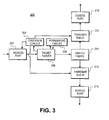
Figure 3 shows a schematic diagram of a portion of aswitch 200 according to an embodiment of theswitch 10 shown inFigure 1 and switches 110 shown inFigure 2 . Theswitch 200 may comprise a plurality of ports coupled to links. In the presently illustrated embodiment, anegress port 202 receives data packets which may be forwarded to any of a plurality ofegress ports 210. In one embodiment, any port of theswitch 200 may be aningress port 202 to receive data packets from an associated link or an egress port to transmit data packets on the link. In other embodiments, particular ports on theswitch 200 may have fixed functionality as an ingress port or an egress port. - In the presently illustrated embodiment, the ports of the
switch 200 may transmit or receive data packets on serial links coupled to devices according to a data packet format.Figure 4 shows a format of adata packet 250 which may be received at an ingress port and forwarded to an egress port of theswitch 200. Thedata packet 250 comprises aheader portion 252, apayload portion 254 and atail portion 256. Theheader portion 252 may comprise information associating thedata packet 250 with a data packet type and destination information associated with a destination device to receive thedata packet 250. - According to an embodiment, the
data packet 250 may be associated with any one of several data packet types such as, for example, a request packet type or a completion packet type. However, these are merely examples of data packet types and embodiments of the present invention are not limited in these respects. In one embodiment, theheader portion 252 may maintain destination information in different formats depending upon the data packet type associated with thedata packet 250. Accordingly, theswitch 200 may extract destination information from theheader portion 252 based upon the associated data packet type. Thetail portion 256 of thedata packet 250 may comprise information such as, for example, a CRC or a packet valid symbol. -
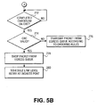
Figures 5A and5B show a flow diagram illustrating a process to forward data packets from an ingress port to an egress port according to an embodiment of the present invention as illustrated inFigures 3 and4 . Atblock 262, thepacket parser 262 may extract data packet type information from theheader portion 252 of a data packet received at theingress port 202 and initiate a checksum calculation on data in the received data packet atchecksum circuit 204. Based upon the extracted data packet type information, atblock 264 thepacket parser 208 may associate theheader portion 252 of the received data packet with a header format. Theparser 208 may then extract destination information from particular fields in theheader portion 252 based upon the header format. - At
block 266, thepacket parser 208 and forwardingcircuit 206 may determine routing information from the extracted destination information (e.g., according to a look up table) and select anegress port 210 based upon the routing information. Atblock 268, thepacket parser 208 may determine whether the transmit queue 212 (associated with the selected egress port 210) is capable of receiving the data packet. If the transmitqueue 212 is capable of receiving the data packet (e.g., transmit queue not full), atblock 270 theforwarding circuit 206 may then initiate the forwarding of the data packet through theswitch fabric 214 to the transmitqueue 212. - In the presently illustrated embodiment, it should be understood that the
switch fabric 214 may forward the received data packet to the transmitqueue 212 prior to completion of the checksum operation (initiated at block 264). Theswitch fabric 214 may begin "streaming" the leading portion of the received data packet to a transmitqueue 212 upon a selection of theegress port 210 concurrently with execution of the checksum operation by thechecksum circuit 204. Upon completion of the checksum operation atdiamond 272, thechecksum circuit 204 may provide a CRC status indication to theingress port 202 and the selected transmitqueue 212. If the CRC status is valid, the data packet may be transmitted from the selected transmitqueue 212 through the corresponding egress port according to ordering rules atblock 276. If the CRC status is invalid, the data packet may be dropped from the transmit queue atblock 278 and theingress port 202 may initiate a link level retry atblock 280 for retransmission of the data packet to theingress port 202. Upon dropping the invalid data packet, the selected transmitqueue 212 may then re-adjust space availability to enqueue an additional data packet for transmission. - In an alternative embodiment, upon receipt of an invalid CRC status at
diamond 274, the selected transmitqueue 212 may insert a symbol in thetail portion 256 of the forwarded data packet indicating that the data packet is invalid. This may allow theegress port 210 to begin transmission of the data packet from the transmitqueue 212 prior to receipt of an invalid CRC status from the checksum circuit 204 (provided that the symbol is inserted prior to the completion of transmission of the data packet from the transmit queue 212). A device receiving the data packet (not shown) may then recognize that the data packet is invalid from the inserted symbol and discard the data packet after being forwarded on a link. The receiving device may then initiate a link level retry for retransmission of the data packet from theswitch 200. Theswitch 200 may then initiate a link level retry on the ingress port for retransmission of the data packet. Theswitch 200 may then satisfy the link level retry from the receiving device in response to receipt of the retransmitted data packet. -
Figures 6A through 6E show formats for a packet header received at an ingress port of a switch according to an alternative embodiment of thedata packet 250 shown inFigure 4 . Here, the ingress port may receive the data packet from a serial link according to a PCI (3GI0) format. It should be understood that the presently illustrated embodiment may be applied in forwarding 32-bit or 64-bit addressable Request packets (Figures 6A and 6B ) as well as Configuration Request packets (Figure 6D ) and Request Completion Packets (Figure 6E ). - Each of the data packet headers comprise a symbol at
byte 0 indicating a corresponding data packet type such as, for example, a request packet, a request completion packet or a configuration packet. However, these are merely examples of data packet types that may be indicated in a set field of a packet header and such a field may indicate other data packet types. - In the presently illustrated embodiment, different types of destination information in the packet header formats shown in
Figures 6A through 6E may be associated with routing information to determine a destination transmitqueue 212 andegress port 210. Based upon a particular data packet type, according to an embodiment, destination information may comprise a destination device identifier or a physical destination address (e.g., a PCI configuration address to locate a device or device function in an enumeration process, link layer address or an egress port number). It should be understood, however, that these are merely examples of destination information that may be associated with routing information (e.g., in a look up table) to select a destination transmitqueue 212 and embodiments of the present invention are not limited in these respects. -
Figure 7 shows a flow diagram illustrating an embodiment to process data packets received at an ingress port with headers formatted as illustrated inFigures 6A through 6E . Upon receipt of a data packet from a serial link at theingress port 202, thepacket parser 208 may extract data packet type information from thebyte 0 location of the data packet header. Atdiamond 504, the received data packet may be classified as either a request packet or a request completion packet based upon the extracted data packet type information. Atblocks packet parser 208 may determine the data packet size from the size of the packet header (based upon the extracted data packet type information) added to the size of the packet payload from the "length" field inbytes - If the received data packet is classified as a request packet (e.g., as shown in
Figures 6A and 6B ), atblock 508 thepacket parser 208 may extract destination information (e.g., a destination address) atbytes 4 through 7 if the request packet uses 32-bit addressing or atbytes 4 through 11 if the request packet uses 64-bit addressing. Theforwarding circuit 206 may then select an egress port from a look up table based upon routing information associated with the destination information. - If the received data packet is classified as a request completion packet (e.g., as shown in
Figure 6E ), atblock 508 thepacket parser 208 may extract information from the packet header identifying the source of the underlying request from a "source ID"or "requester ID" field atbytes 8 and 9. Theforwarding circuit 206 may then select an egress port from routing information in a look up table associating the source ID or Requestor ID with an egress port. - In addition to a "request" or "completion" data packet type, according to an embodiment, other data packet types may include a PCI configuration request (e.g., a configuration read or write request) where a header may comprise data identifying a physical configuration address (e.g., bus number, device number and/or device function number). Upon determining that the data packet is of a configuration request type, the physical configuration address may be associated with routing information in a look up table to identify an egress port. Responses to such a configuration request data packet may then be processed as a completion data packet type.
- Upon selection of an egress port at either block 508 or 524, the received data packet may be forwarded to a transmit queue of the selected egress port at
block 512 if the transmit queue is available to receive the data packet (diamond 510). It should be understood, however, that the forwarding of the data packet to the transmit queue of the egress port (e.g., through a switch fabric) may commence prior to execution of a checksum operation to determine a valid CRC. Transmission of the data packet from the transmit queue through the egress port may be suspended atdiamond 514 until completion of the checksum operation. If the checksum operation validates the CRC portion of the data packet, the data packet may be transmitted from the transmit queue according to ordering rules atoval 520. Otherwise, if the checksum operation indicates an invalid CRC, the data packet may be dropped from the transmit queue and a link level retry may be initiated at the ingress port atoval 520. - In an alternative embodiment, transmission from the transmit queue may commence prior to validation of the CRC by the checksum operation (e.g., at diamond 514). In this embodiment, transmission from the transmit queue may not be suspended until receipt of a CRC validation. Instead, an invalid packet symbol may be inserted in the tail portion of the data packet prior to completion of transmission from the egress port. Upon receipt of the data packet transmitted from the egress port and detection of the invalid symbol, the receiving device may discard the received data packet and attempt a link level retry. Upon receipt of a re-transmitted data packet (in response to a link level retry at the ingress port of the switch), the re-transmitted data packet may be forwarded to the transmit queue and re-transmitted through the egress port.
-
Figure 8 shows a schematic diagram mapping of a multi-port switch to a representation of a "virtual" PCI bus structure according to an embodiment of theswitch 200 shown inFigure 3 . Aswitch 610 may comprise anupstream port 622 coupled to aroot device 604 and a plurality ofdownstream ports 624 coupled torespective devices 618. In one embodiment, thedevices 618 may be PCI devices adaptable to provide an "endpoint" as described in the PCI Express Specification. Alternatively, thedevices 618 may comprise other interfaces to communicate with thedownstream ports 624 according to other protocols such as, for example, Infiniband, Rapid I/O or Hyper Transport protocols. However, these are merely examples of an interface for devices which may be coupled to a downstream port of a switch and embodiments of the present invention are not limited in these respects. - According to an embodiment, the
switch 610 comprises logic and circuitry to forward data messages or data packets received on a source ingress port (e.g., theupstream port 622 or a downstream port 24) to a different destination egress port (e.g., theupstream port 622 or a downstream port 624). Theswitch 610 may comprise logic to associate the destination address information with routing information (e.g., routing information stored in a routing table or look-up table) to identify the destination egress port. However, this is merely an example of logic in a switch to forward data messages or data packets from an ingress port to an egress port, and embodiments of the present invention are not limited in this respect. - A processing system (not shown) may configure resources enabling processes hosted on the processing system to communicate with the
devices 618 by executing an enumeration procedure. For example, the processing system may execute an enumeration procedure to configure resources to communicate with theswitch 622 as PCI devices according to the PCI Local Bus Specification as illustrated in avirtual mapping 600. For example, routines in operating systems such as versions of Windows® sold by Microsoft Corporation, Linux, Solaris® sold by Sun Microsystems, or VxWorks® or pSOS® sold by WindRiver Systems, Inc. may execute an enumeration procedure to configure resources at the processing system according to the virtual mapping. However, these are merely examples of routines which may execute an enumeration procedure and embodiments of the present invention are not limited in this respect. - In the illustrated embodiment, the
switch 610 may appear to the processing system as one or more devices coupled to a PCI bus at theroot device 604. Theswitch 610 may comprise logic to respond toType 0 orType 1 configuration requests received at theupstream port 622 from a PCI enumeration procedure. In the course of aninitial Type 0 configuration transaction, theswitch 610 may provide a configuration header as illustrated inChapter 3 of the PCI-to-PCI Bridge Architecture Specification, Rev. 1.1, December 18, 1998, PCI Special Interest Group (hereinafter the "PCI-to-PCI Bridge Specification") to emulate or identify a "virtual" PCI-to-PCI bridge 620. The enumeration procedure may then allocate resources at the processing system to communicate with the upstream port 222 as the virtual PCI-to-PCI bridge 620. - Following the
initial Type 0 configuration transaction at theupstream port 622, the enumeration procedure may initiatesubsequent Type 1 configuration transactions (as illustrated in section 3.1.2.1.1 of the PCI-to-PCI Bridge Specification) at theupstream port 622 to allocate resources enabling communication with each of thedownstream ports 624 as a virtual PCI-to-PCI bridge 206. In the course of each of theseType 1 configuration transactions, logic at theswitch 210 may provide at the upstream port 622 a configuration header identifying a correspondingdownstream port 624 as an emulated or virtual PCI-to-PCI bridge 606 coupled to a secondary bus of the virtual PCI-to-PCI bridge 620. Such logic at theswitch 610 may emulate aType 1 toType 0 configuration transaction conversion as illustrated in Section 3.2 of the PCI-to-PCI Bridge Specification. - Following each
Type 1 configuration transaction to configure resources at the processing system to communicate with a corresponding emulated or virtual PCI-to-PCI bridge 606, the enumeration procedure may initiate asubsequent Type 1 configuration at theupstream port 622 directed to the emulated or virtual PCI-to-PCI bridge 606. Theswitch 610 may comprise logic to provide a configuration header identifying acorresponding device 618 as avirtual PCI device 608 coupled to an emulated secondary bus of the emulated or virtual PCI-to-PCI bridge 606. Such logic at theswitch 610 may emulateType 1 toType 1 configuration transaction forwarding as illustrated in section 3.1.2.1.2 of the PCI-to-PCI Bridge Specification. - According to an embodiment, a
downstream port 624 may be coupled to adevice 618 through a serial link (not shown). In response to aType 1 configuration request to a corresponding virtual PCI-to-PCI bridge 606, theswitch 610 may provide a response to emulate the presence of a PCI bus segment. In response to the indication from theswitch 610, the enumeration procedure may associate a bus segment number with the serial link, and allocate resources to the serial link as a PCI bus segment with a single device. However, this is merely an example of how the presence of a bus segment may be emulated in an enumeration procedure and embodiments of the present invention are not limited in this respect. - In the illustrated embodiment, a downstream data packet received at the
upstream port 622 from the root device may be associated with destination information comprising an address. Theswitch 610 may comprise logic to define ranges of addresses for forwarding such downstream data messages to one of thedevices 618 coupled to adownstream port 624. For example, theswitch 610 may define base and limit registers for each address range associated with each downstream port. A data message received from theroot device 604 having an address within an address range defined by such base and limit registers may then be forwarded to thedownstream port 624 associated with the address range. Theswitch 610 may then ignore downstream messages from the root device having an address which does not fall within an address range associated with any of thedownstream ports 624. - According to an embodiment, the
switch 610 may define base and limit registers for each address range in the course of an enumeration procedure.Figure 4 shows a schematic diagram illustrating downstream forwarding address ranges over anaddress map 650 defined by a switch according to an embodiment of themulti-port switch 610 shown inFigure 3 . In the illustrated embodiment, the switch defines address ranges 654, 656 and 658 (e.g., including base and limit registers) for forwarding downstream messages to respective downstream ports. According to an embodiment, the enumeration procedure may model each downstream message address range for a downstream port as an address range for forwarding messages from a primary bus to a secondary bus of a virtual PCI-to-PCI bridge 606 corresponding with the downstream port. Similarly, the enumeration procedure may also model the union of the downstream message address ranges for all downstream ports (e.g., the union of the address ranges 654, 656 and 658) as an address range for forwarding messages from a primary bus to a secondary bus of the virtual PCI-to-PCI bridge 620. - According to an embodiment, the multi-port switch illustrated with reference to
Figures 8 and9 may comprise logic to inversely decode the address ranges 654, 656 and 658 (for forwarding downstream messages from theupstream port 622 to the downstream ports 624) to provide address ranges for forwarding messages fromdownstream ports 624 to theupstream port 622. Accordingly, theswitch 610 may forward data messages or packets received at adownstream port 624 to theupstream port 622 if the received data message or packet is associated with a destination address in eitheraddress range PCI bridge 620 as illustrated inChapter 4 of the PCI-to-PCI Bridge Specification. - According to an embodiment, the
switch 610 may also comprise logic to forward a data message or data packet received at a firstdownstream port 624 to a second, destinationdownstream port 624 independently of the processing system. Such logic at theswitch 610 may use destination information associated with the received data message or data packet to inversely decode a destination downstream port 625 from the address ranges 254, 256 and 258 defined for forwarding messages from theupstream port 622. Theswitch 610 may then forward the received data message or data packet to the inversely decodeddownstream port 624. However, this is merely an example of how a switch may forward data packets or messages from a first downstream port to a second downstream port, and embodiments of the present invention are not limited in this respect. - According to an embodiment, the
switch 610 may comprise a memory to maintain routing information in a routing table to forward data message or data packets to a destinationupstream port 622 ordownstream port 624. For example, theswitch 610 may comprise logic to build a look-up table to associate address ranges 654, 656 and 658 with respectivedownstream ports 624 in response to the enumeration procedure, and associate the remaining address ranges 652 and 660 with theupstream port 622. However, this is merely an example of how a switch may maintain routing information to forward data messages or data packets to destination ports and embodiments of the present invention are not limited in this respect. -
Figure 10 shows a flow diagram illustrating an enumeration procedure according to an embodiment of the multi-port switch shown inFigures 8 and9 . In the illustrated embodiment, a processing system may initiate an enumeration procedure to allocate resources to communicate with theswitch 610 as one or more PCIdevices using Type 0 andType 1 configuration transactions as illustrated inChapter 3 of the PCI-to-PCI Bridge Specification. - At block 302, a
Type 0 configuration transaction is initiated at an upstream port of a switch, and the upstream port may return a configuration header identifying a virtual PCI-to-PCI bridge. The enumeration procedure may then initiate subsequent configuration transactions at the upstream port to enumerate additional devices located "behind" the upstream port (e.g., directed to a device coupled to the secondary bus of the virtual PCI-to-PCI bridge) atblocks 706 through 710. For each downstream port of the switch, the enumeration procedure atblock 706 may initiate aType 1 configuration transaction (including aType 1 toType 0 conversion) at the upstream port to enumerate the downstream port as a virtual PCI-to-PCI bridge on a secondary bus of the virtual PCI-to-PCI bridge corresponding with the upstream port as illustrated in section 3.1.2.1.1 of the PCI-to-PCI Bridge Specification. - The upstream port may provide a configuration header identifying an associated downstream port as a PCI-to-PCI bridge in response to the
Type 1 configuration transaction initiated at block 306. Accordingly, the enumeration procedure may initiate asubsequent Type 1 configuration transaction atblock 708 directed to a device on the secondary bus of the virtual PCI-to-PCI bridge corresponding with the downstream port (including aType 1 toType 1 forwarding) as illustrated in section 3.1.2.1.2 of the PCI-to-PCI Bridge Specification. In response to theType 1 configuration transaction initiated atblock 710, the upstream port may provide a configuration header identifying the device coupled to the downstream port as a PCI device. - According to an embodiment, the switch comprises logic to provide a configuration header at the upstream port in response to the
Type 1 configuration transaction initiated at block 308 based upon information identifying the device coupled to the downstream port. For example, the device at the downstream port may transmit a configuration header to the switch identifying the device as a PCI device. The switch may then forward the configuration header to the upstream port in response to theType 1 configuration transaction. Alternatively, the switch may comprise logic to form a configuration based upon information identifying one or more functions of the device received at the downstream port. However, this is merely an example of how switch may form a PCI configuration header to characterize a device or function of a device coupled to a downstream port, and embodiments of the present invention are not limited in this respect. - At
block 710, the switch may define a range of addresses for forwarding messages from the upstream port to the device. Such a range of addresses may be represented by base and limit registers defined at the upstream port. Following the enumeration procedure atblocks 702 through 712, the switch may use inverse decoding to forward messages from downstream ports to the upstream port, or from a first downstream data port to a second downstream data port as discussed above with reference toFigure 9 . For example, the switch may comprise logic to extract routing information from inversely decoding the address ranges associated with the downstream data ports to form a routing table. The routing table may then be used to forward data messages from a source downstream port to the upstream port or a destination downstream port. - While there has been illustrated and described what are presently considered to be example embodiments of the present invention, it will be understood by those skilled in the art that various other modifications may be made, and equivalents may be substituted, without departing from the true scope of the invention. Additionally, many modifications may be made to adapt a particular situation to the teachings of the present invention without departing from the central inventive concept described herein. Therefore, it is intended that the present invention not be limited to the particular embodiments disclosed, but that the invention include all embodiments falling within the scope of the appended claims.
Claims (30)
- A method comprising the steps of:receiving a data packet at an ingress port of a switch;initiating a checksum operation on a portion of the received data packet, characterized in that, said method further comprises the step ofcommencing forwarding the received data packet through a switch fabric to a transmit queue of an egress port of the switch prior to completion of the checksum operation.
- The method of claim 1, the method further comprising selectively transmitting the forwarded data packet from the transmit queue in response to a valid CRC indication from the checksum operation.
- The method of claim 2, the method further comprising selectively dropping the forwarded data packet from the transmit queue in response to an invalid CRC indication from the checksum operation.
- The method of claim 1, the method further comprising inserting a packet invalid symbol into the forwarded data packet in response to an invalid CRC indication from the checksum operation.
- The method of claim 1, the method further comprising selecting the egress port based upon a portion of the received data packet.
- The method of claim 5, the method further comprising:associating the received data packet with a data packet type based upon a portion of the received data packet;extracting destination information from a portion of the received data packet based upon the associated data packet type; andselecting the egress port based upon the destination information.
- The method of claim 6, the method further comprising:selecting the egress port based upon a physical address in the received data packet with the egress port if the received data packet is associated with a request data packet type; andselecting the egress port based upon an identifier of a source of a request data packet if the received data packet is associated a request completion data packet type.
- The method of claim 1, the method further comprising:determining an availability of the egress port to transmit the received data packet; andselectively forwarding the received data packet to the transmit queue based upon the availability of the egress port.
- A switch comprising:a plurality of ports coupled to a switch fabric, at least one port comprising a transmit queue;a checksum circuit to execute a checksum operation on at least a portion of a data packet received at an ingress port; characterized in that said switch further comprisesa forwarding circuit to commence forwarding the received data packet through the switch fabric to a transmit queue of an egress port prior to completion of the checksum operation.
- The switch of claim 9, wherein the egress port comprises logic to selectively transmit the forwarded data packet from the transmit queue in response to a valid CRC indication from the checksum operation.
- The switch of claim 10, wherein the egress port comprises logic to selectively drop the forwarded data packet from the transmit queue in response to an invalid CRC indication from the checksum operation.
- The switch of claim 9, the switch further comprising logic to insert a packet invalid symbol into the forwarded data packet in response to an invalid CRC indication from the checksum operation.
- The switch of claim 9, wherein the forwarding circuit comprises logic to select the egress port based upon a portion of the received data packet.
- The switch of claim 13, wherein the forwarding circuit further comprises:logic to associate the received data packet with a data packet type based upon a portion of the received data packet;logic to extract destination information from a portion of the received data packet based upon the associated data packet type; andlogic to select the egress port based upon the destination information.
- The switch of claim 14, wherein the forwarding circuit further comprises:logic to select the egress port based upon a physical address in the received data packet with the egress port if the received data packet is associated with a request data packet type; andlogic to select the egress port based upon an identifier of a source of a request data packet if the received data packet is associated a request completion data packet type.
- The switch of claim 9, wherein the forwarding circuit further comprises:logic to determine an availability of the egress port to transmit the received data packet; andlogic to selectively forward the received data packet to the transmit queue based upon the availability of the egress port.
- A system comprising:a switch comprising:a plurality of ports coupled to a switch fabric, at least one port comprising a transmit queue;a checksum circuit to execute a checksum operation on at least a portion of a data packet received at an ingress port; anda forwarding circuit to commence forwarding the received data packet through the switch fabric to a transmit queue of an egress port prior to completion of the checksum operation;a host processing system coupled to an upstream port of the switch through a root device; andone or more devices coupled to downstream ports of the switch.
- The system of claim 17, wherein the egress port comprises logic to selectively transmit the forwarded data packet from the transmit queue in response to a valid CRC indication from the checksum operation.
- The system of claim 18, wherein the egress port comprises logic to selectively drop the forwarded data packet from the transmit queue in response to an invalid CRC indication from the checksum operation.
- The system of claim 17, wherein the switch further comprises logic to insert a packet invalid symbol into the forwarded data packet in response to an invalid CRC indication from the checksum operation.
- The system of claim 17, wherein the forwarding circuit comprises logic to select the egress port based upon a portion of the received data packet.
- The system of claim 22, wherein the forwarding circuit further comprises:logic to associate the received data packet with a data packet type based upon a portion of the received data packet;logic to extract destination information from a portion of the received data packet based upon the associated data packet type; andlogic to select the egress port based upon the destination information.
- The system of claim 22, wherein the forwarding circuit further comprises:logic to select the egress port based upon a physical address in the received data packet with the egress port if the received data packet is associated with a request data packet type; andlogic to select the egress port based upon an identifier of a source of a request data packet if the received data packet is associated a request completion data packet type.
- The system of claim 17, wherein the forwarding circuit further comprises:logic to determine an availability of the egress port to transmit the received data packet; andlogic to selectively forward the received data packet to the transmit queue based upon the availability of the egress port.
- The system of claim 17, wherein the switch comprises logic to emulate the presence of a PCI-to-PCI bridge in response to receipt of a configuration request packet at the upstream port.
- The system of claim 17, wherein at least one downstream port is coupled to a graphics controller.
- The system of claim 17, wherein at least one downstream port is coupled to a small computer system interfaced scsi.
- The system of claim 17, wherein at least one downstream port is coupled to an Ethernet controller.
- The system of claim 17, wherein at least one downstream port is coupled to a Fiberchannel interface.
- The system of claim 17, wherein at least one downstream port is coupled to a serial ATA device.
Applications Claiming Priority (3)
| Application Number | Priority Date | Filing Date | Title |
|---|---|---|---|
| US10/226,838 US7251704B2 (en) | 2002-08-23 | 2002-08-23 | Store and forward switch device, system and method |
| US266838 | 2002-08-23 | ||
| PCT/US2003/026245 WO2004019562A2 (en) | 2002-08-23 | 2003-08-22 | Store and forward switch device, system and method |
Publications (2)
| Publication Number | Publication Date |
|---|---|
| EP1530850A2 EP1530850A2 (en) | 2005-05-18 |
| EP1530850B1 true EP1530850B1 (en) | 2008-03-05 |
Family
ID=31887329
Family Applications (1)
| Application Number | Title | Priority Date | Filing Date |
|---|---|---|---|
| EP03793243A Expired - Lifetime EP1530850B1 (en) | 2002-08-23 | 2003-08-22 | Store and forward switch device, system and method |
Country Status (10)
| Country | Link |
|---|---|
| US (1) | US7251704B2 (en) |
| EP (1) | EP1530850B1 (en) |
| KR (1) | KR100666515B1 (en) |
| CN (1) | CN100586097C (en) |
| AT (1) | ATE388554T1 (en) |
| AU (1) | AU2003259978A1 (en) |
| DE (1) | DE60319543T2 (en) |
| HK (1) | HK1071822A1 (en) |
| TW (1) | TWI280011B (en) |
| WO (1) | WO2004019562A2 (en) |
Families Citing this family (82)
| Publication number | Priority date | Publication date | Assignee | Title |
|---|---|---|---|---|
| US7483967B2 (en) * | 1999-09-01 | 2009-01-27 | Ximeta Technology, Inc. | Scalable server architecture based on asymmetric 3-way TCP |
| US7792923B2 (en) | 2000-10-13 | 2010-09-07 | Zhe Khi Pak | Disk system adapted to be directly attached to network |
| US7783761B2 (en) * | 2001-07-16 | 2010-08-24 | Zhe Khi Pak | Scheme for dynamically connecting I/O devices through network |
| US20050149682A1 (en) * | 2001-10-09 | 2005-07-07 | Han-Gyoo Kim | Virtual multiple removable media jukebox |
| US7415652B1 (en) * | 2002-08-19 | 2008-08-19 | Marvell International Ltd. | Out of order checksum calculation for fragmented packets |
| US7313090B2 (en) * | 2002-09-26 | 2007-12-25 | Avago Technologies General Ip (Singapore) Pte. Ltd. | Systems and methods for providing data packet flow control |
| US7457880B1 (en) | 2003-09-26 | 2008-11-25 | Ximeta Technology, Inc. | System using a single host to receive and redirect all file access commands for shared data storage device from other hosts on a network |
| US7337371B2 (en) * | 2003-12-30 | 2008-02-26 | Intel Corporation | Method and apparatus to handle parity errors in flow control channels |
| US7664836B2 (en) * | 2004-02-17 | 2010-02-16 | Zhe Khi Pak | Device and method for booting an operation system for a computer from a passive directly attached network device |
| US20060069884A1 (en) * | 2004-02-27 | 2006-03-30 | Han-Gyoo Kim | Universal network to device bridge chip that enables network directly attached device |
| US7639616B1 (en) | 2004-06-08 | 2009-12-29 | Sun Microsystems, Inc. | Adaptive cut-through algorithm |
| US7733855B1 (en) | 2004-06-08 | 2010-06-08 | Oracle America, Inc. | Community separation enforcement |
| US7257758B1 (en) * | 2004-06-08 | 2007-08-14 | Sun Microsystems, Inc. | Stumping mechanism |
| US7602712B2 (en) * | 2004-06-08 | 2009-10-13 | Sun Microsystems, Inc. | Switch method and apparatus with cut-through routing for use in a communications network |
| US7860096B2 (en) * | 2004-06-08 | 2010-12-28 | Oracle America, Inc. | Switching method and apparatus for use in a communications network |
| US8964547B1 (en) | 2004-06-08 | 2015-02-24 | Oracle America, Inc. | Credit announcement |
| KR100698256B1 (en) * | 2004-07-16 | 2007-03-22 | 엘지전자 주식회사 | A Speaker Equipment using Display Window |
| US7746900B2 (en) | 2004-07-22 | 2010-06-29 | Zhe Khi Pak | Low-level communication layers and device employing same |
| US20060067356A1 (en) * | 2004-08-23 | 2006-03-30 | Han-Gyoo Kim | Method and apparatus for network direct attached storage |
| US7860943B2 (en) * | 2004-08-23 | 2010-12-28 | Zhe Khi Pak | Enhanced network direct attached storage controller |
| US7404090B1 (en) | 2004-10-15 | 2008-07-22 | National Semiconductor Corporation | Device and computer system for power management using serial link connections |
| US8706942B2 (en) * | 2004-12-29 | 2014-04-22 | Intel Corporation | Direct memory access (DMA) address translation between peer-to-peer input/output (I/O) devices |
| US7849257B1 (en) | 2005-01-06 | 2010-12-07 | Zhe Khi Pak | Method and apparatus for storing and retrieving data |
| JP4398386B2 (en) * | 2005-01-28 | 2010-01-13 | 富士通株式会社 | Device for interconnecting multiple processing nodes via serial bus |
| KR100645537B1 (en) | 2005-02-07 | 2006-11-14 | 삼성전자주식회사 | Method of dynamic Queue management for the stable packet forwarding and Element of network thereof |
| US8176204B2 (en) * | 2005-03-11 | 2012-05-08 | Hewlett-Packard Development Company, L.P. | System and method for multi-host sharing of a single-host device |
| US7697536B2 (en) | 2005-04-01 | 2010-04-13 | International Business Machines Corporation | Network communications for operating system partitions |
| US7586936B2 (en) * | 2005-04-01 | 2009-09-08 | International Business Machines Corporation | Host Ethernet adapter for networking offload in server environment |
| US7508771B2 (en) * | 2005-04-01 | 2009-03-24 | International Business Machines Corporation | Method for reducing latency in a host ethernet adapter (HEA) |
| US7903687B2 (en) * | 2005-04-01 | 2011-03-08 | International Business Machines Corporation | Method for scheduling, writing, and reading data inside the partitioned buffer of a switch, router or packet processing device |
| US7706409B2 (en) * | 2005-04-01 | 2010-04-27 | International Business Machines Corporation | System and method for parsing, filtering, and computing the checksum in a host Ethernet adapter (HEA) |
| US7577151B2 (en) | 2005-04-01 | 2009-08-18 | International Business Machines Corporation | Method and apparatus for providing a network connection table |
| US20060221953A1 (en) * | 2005-04-01 | 2006-10-05 | Claude Basso | Method and apparatus for blind checksum and correction for network transmissions |
| US7881332B2 (en) * | 2005-04-01 | 2011-02-01 | International Business Machines Corporation | Configurable ports for a host ethernet adapter |
| US7606166B2 (en) * | 2005-04-01 | 2009-10-20 | International Business Machines Corporation | System and method for computing a blind checksum in a host ethernet adapter (HEA) |
| US7492723B2 (en) * | 2005-07-07 | 2009-02-17 | International Business Machines Corporation | Mechanism to virtualize all address spaces in shared I/O fabrics |
| US7496045B2 (en) * | 2005-07-28 | 2009-02-24 | International Business Machines Corporation | Broadcast of shared I/O fabric error messages in a multi-host environment to all affected root nodes |
| US8189603B2 (en) * | 2005-10-04 | 2012-05-29 | Mammen Thomas | PCI express to PCI express based low latency interconnect scheme for clustering systems |
| US7631050B2 (en) * | 2005-10-27 | 2009-12-08 | International Business Machines Corporation | Method for confirming identity of a master node selected to control I/O fabric configuration in a multi-host environment |
| US7430630B2 (en) * | 2005-10-27 | 2008-09-30 | International Business Machines Corporation | Routing mechanism in PCI multi-host topologies using destination ID field |
| US7395367B2 (en) | 2005-10-27 | 2008-07-01 | International Business Machines Corporation | Method using a master node to control I/O fabric configuration in a multi-host environment |
| US7474623B2 (en) | 2005-10-27 | 2009-01-06 | International Business Machines Corporation | Method of routing I/O adapter error messages in a multi-host environment |
| US7363404B2 (en) * | 2005-10-27 | 2008-04-22 | International Business Machines Corporation | Creation and management of destination ID routing structures in multi-host PCI topologies |
| US7793010B2 (en) * | 2005-11-22 | 2010-09-07 | Lsi Corporation | Bus system with multiple modes of operation |
| US20070136458A1 (en) * | 2005-12-12 | 2007-06-14 | Boyd William T | Creation and management of ATPT in switches of multi-host PCI topologies |
| JP2007172008A (en) * | 2005-12-19 | 2007-07-05 | Sony Corp | Information-processing system, receiver, and program |
| US20070165596A1 (en) * | 2006-01-18 | 2007-07-19 | Boyd William T | Creation and management of routing table for PCI bus address based routing with integrated DID |
| US7707465B2 (en) * | 2006-01-26 | 2010-04-27 | International Business Machines Corporation | Routing of shared I/O fabric error messages in a multi-host environment to a master control root node |
| US7664898B2 (en) * | 2006-02-01 | 2010-02-16 | Broadcom | Method and system for efficient framing on addressed buses |
| US7380046B2 (en) * | 2006-02-07 | 2008-05-27 | International Business Machines Corporation | Method, apparatus, and computer program product for routing packets utilizing a unique identifier, included within a standard address, that identifies the destination host computer system |
| US7484029B2 (en) | 2006-02-09 | 2009-01-27 | International Business Machines Corporation | Method, apparatus, and computer usable program code for migrating virtual adapters from source physical adapters to destination physical adapters |
| JP4775846B2 (en) | 2006-03-20 | 2011-09-21 | 株式会社日立製作所 | Computer system and method for controlling allocation of physical links |
| TWI335517B (en) * | 2006-08-25 | 2011-01-01 | Via Tech Inc | Method of requests access and scheduling and related apparatus thereof |
| US7571273B2 (en) * | 2006-12-06 | 2009-08-04 | International Business Machines Corporation | Bus/device/function translation within and routing of communications packets in a PCI switched-fabric in a multi-host environment utilizing multiple root switches |
| US20080137676A1 (en) * | 2006-12-06 | 2008-06-12 | William T Boyd | Bus/device/function translation within and routing of communications packets in a pci switched-fabric in a multi-host environment environment utilizing a root switch |
| US8316377B2 (en) * | 2007-09-06 | 2012-11-20 | Hewlett-Packard Development Company, L.P. | Sharing legacy devices in a multi-host environment |
| US7991941B2 (en) * | 2008-01-15 | 2011-08-02 | Alcatel Lucent | Memory access assist |
| JP5042372B2 (en) * | 2008-02-26 | 2012-10-03 | ヒューレット−パッカード デベロップメント カンパニー エル.ピー. | Method and apparatus for performing a host enumeration process |
| US8458550B2 (en) * | 2008-03-07 | 2013-06-04 | Nokia Siemens Networks Oy | Protocols for multi-hop relay system with centralized scheduling |
| JP5180729B2 (en) * | 2008-08-05 | 2013-04-10 | 株式会社日立製作所 | Computer system and bus allocation method |
| KR100947618B1 (en) * | 2008-08-27 | 2010-03-15 | 한국전자통신연구원 | Data Processing System |
| US8335213B2 (en) * | 2008-09-11 | 2012-12-18 | Juniper Networks, Inc. | Methods and apparatus related to low latency within a data center |
| US8340088B2 (en) * | 2008-09-11 | 2012-12-25 | Juniper Networks, Inc. | Methods and apparatus related to a low cost data center architecture |
| US9847953B2 (en) * | 2008-09-11 | 2017-12-19 | Juniper Networks, Inc. | Methods and apparatus related to virtualization of data center resources |
| US8755396B2 (en) * | 2008-09-11 | 2014-06-17 | Juniper Networks, Inc. | Methods and apparatus related to flow control within a data center switch fabric |
| US20100061367A1 (en) * | 2008-09-11 | 2010-03-11 | Pradeep Sindhu | Methods and apparatus related to lossless operation within a data center |
| US8730954B2 (en) * | 2008-09-11 | 2014-05-20 | Juniper Networks, Inc. | Methods and apparatus related to any-to-any connectivity within a data center |
| US8265071B2 (en) | 2008-09-11 | 2012-09-11 | Juniper Networks, Inc. | Methods and apparatus related to a flexible data center security architecture |
| US11271871B2 (en) | 2008-09-11 | 2022-03-08 | Juniper Networks, Inc. | Methods and apparatus related to a flexible data center security architecture |
| US8825015B2 (en) * | 2008-09-18 | 2014-09-02 | Nvidia Corporation | Accessing web pages on communication paths with low bandwidth |
| US8924836B2 (en) | 2008-10-30 | 2014-12-30 | Kabushiki Kaisha Toshiba | Data receiving apparatus, data receiving method, and computer-readable recording medium |
| JP4922279B2 (en) * | 2008-10-30 | 2012-04-25 | 株式会社東芝 | Data receiving apparatus, data receiving method, and data receiving program |
| US9813252B2 (en) | 2010-03-23 | 2017-11-07 | Juniper Networks, Inc. | Multicasting within a distributed control plane of a switch |
| US9240923B2 (en) * | 2010-03-23 | 2016-01-19 | Juniper Networks, Inc. | Methods and apparatus for automatically provisioning resources within a distributed control plane of a switch |
| CN102377636B (en) * | 2010-08-06 | 2014-12-17 | 北京乾唐视联网络科技有限公司 | Service communication method of access network device and system thereof |
| US9282060B2 (en) | 2010-12-15 | 2016-03-08 | Juniper Networks, Inc. | Methods and apparatus for dynamic resource management within a distributed control plane of a switch |
| US8943257B2 (en) | 2011-09-30 | 2015-01-27 | Intel Corporation | Protocol neutral fabric |
| CN103078747B (en) * | 2012-12-28 | 2015-08-19 | 华为技术有限公司 | PCIe switch and method of work thereof |
| KR101730991B1 (en) | 2014-10-28 | 2017-04-28 | 삼성전자주식회사 | Storage device and operating method of storage device |
| FR3086824A1 (en) * | 2018-10-02 | 2020-04-03 | Orange | METHOD FOR PRESERVING A DATA TRANSMISSION RATE OF A TERMINAL IN A COMMUNICATIONS NETWORK |
| CN112446474B (en) | 2019-08-31 | 2022-11-22 | 安徽寒武纪信息科技有限公司 | Chip, multichip system, electronic equipment and data transmission method |
| US11386031B2 (en) | 2020-06-05 | 2022-07-12 | Xilinx, Inc. | Disaggregated switch control path with direct-attached dispatch |
Family Cites Families (9)
| Publication number | Priority date | Publication date | Assignee | Title |
|---|---|---|---|---|
| US5953335A (en) * | 1997-02-14 | 1999-09-14 | Advanced Micro Devices, Inc. | Method and apparatus for selectively discarding packets for blocked output queues in the network switch |
| US6208645B1 (en) * | 1997-05-30 | 2001-03-27 | Apple Computer, Inc. | Time multiplexing of cyclic redundancy functions in point-to-point ringlet-based computer systems |
| US6275888B1 (en) * | 1997-11-19 | 2001-08-14 | Micron Technology, Inc. | Method for configuring peer-to-peer bus bridges in a computer system using shadow configuration registers |
| US6134662A (en) * | 1998-06-26 | 2000-10-17 | Vlsi Technology, Inc. | Physical layer security manager for memory-mapped serial communications interface |
| US6763034B1 (en) * | 1999-10-01 | 2004-07-13 | Stmicroelectronics, Ltd. | Connection ports for interconnecting modules in an integrated circuit |
| WO2001095565A2 (en) * | 2000-06-02 | 2001-12-13 | Inrange Technologies Corporation | Address conversion method and device in a fibre channel switch |
| US6938138B2 (en) * | 2001-01-11 | 2005-08-30 | International Business Machines Corporation | Method and apparatus for managing access to memory |
| US20030115513A1 (en) * | 2001-08-24 | 2003-06-19 | David Harriman | Error forwarding in an enhanced general input/output architecture and related methods |
| KR100750036B1 (en) * | 2001-08-24 | 2007-08-16 | 인텔 코오퍼레이션 | A general input/output architecture, protocol and related methods to implement flow control |
-
2002
- 2002-08-23 US US10/226,838 patent/US7251704B2/en not_active Expired - Fee Related
-
2003
- 2003-08-19 TW TW092122750A patent/TWI280011B/en not_active IP Right Cessation
- 2003-08-22 DE DE60319543T patent/DE60319543T2/en not_active Expired - Lifetime
- 2003-08-22 WO PCT/US2003/026245 patent/WO2004019562A2/en not_active Application Discontinuation
- 2003-08-22 EP EP03793243A patent/EP1530850B1/en not_active Expired - Lifetime
- 2003-08-22 CN CN03800549A patent/CN100586097C/en not_active Expired - Fee Related
- 2003-08-22 KR KR1020057003113A patent/KR100666515B1/en not_active IP Right Cessation
- 2003-08-22 AT AT03793243T patent/ATE388554T1/en not_active IP Right Cessation
- 2003-08-22 AU AU2003259978A patent/AU2003259978A1/en not_active Abandoned
-
2005
- 2005-05-26 HK HK05104417A patent/HK1071822A1/en not_active IP Right Cessation
Also Published As
| Publication number | Publication date |
|---|---|
| AU2003259978A8 (en) | 2004-03-11 |
| US7251704B2 (en) | 2007-07-31 |
| AU2003259978A1 (en) | 2004-03-11 |
| WO2004019562A8 (en) | 2004-07-22 |
| CN1593043A (en) | 2005-03-09 |
| TWI280011B (en) | 2007-04-21 |
| KR20050039859A (en) | 2005-04-29 |
| KR100666515B1 (en) | 2007-01-11 |
| WO2004019562A3 (en) | 2004-09-10 |
| DE60319543T2 (en) | 2009-03-26 |
| CN100586097C (en) | 2010-01-27 |
| WO2004019562A2 (en) | 2004-03-04 |
| HK1071822A1 (en) | 2005-07-29 |
| DE60319543D1 (en) | 2008-04-17 |
| TW200415890A (en) | 2004-08-16 |
| US20040039986A1 (en) | 2004-02-26 |
| EP1530850A2 (en) | 2005-05-18 |
| ATE388554T1 (en) | 2008-03-15 |
Similar Documents
| Publication | Publication Date | Title |
|---|---|---|
| EP1530850B1 (en) | Store and forward switch device, system and method | |
| JP5490336B2 (en) | Prioritizing low latency in a PCI Express multiple root I / O virtualization environment | |
| US6804673B2 (en) | Access assurance for remote memory access over network | |
| US7669000B2 (en) | Host bus adapter with multiple hosts | |
| US7937447B1 (en) | Communication between computer systems over an input/output (I/O) bus | |
| KR101298862B1 (en) | Method and apparatus for enabling id based streams over pci express | |
| US7165131B2 (en) | Separating transactions into different virtual channels | |
| US6694392B1 (en) | Transaction partitioning | |
| JPH06511338A (en) | Method and apparatus for parallel packet bus | |
| WO2001018988A1 (en) | Bridge between parallel buses over a packet-switched network | |
| JP2010514063A (en) | Bridging Serial Advanced Technology Attachment (SATA) and Serial Attached Small Computer System Interface (SCSI) (SAS) | |
| US6606679B2 (en) | Software transparent system and method for peer-to-peer message routing | |
| TW200815990A (en) | Host port redundancy selection | |
| US20110145469A1 (en) | Apparatus for processing peripheral component interconnect express protocol | |
| JP5469081B2 (en) | Control path I / O virtualization method | |
| WO2012009559A1 (en) | System and method for accessing resources of a pci express compliant device | |
| US7460531B2 (en) | Method, system, and program for constructing a packet | |
| US6557060B1 (en) | Data transfer in host expansion bridge | |
| US20080263248A1 (en) | Multi-drop extension for a communication protocol | |
| US20130036243A1 (en) | Host-daughtercard configuration with double data rate bus | |
| TWI240859B (en) | Error forwarding in an enhanced general input/output architecture and related methods |
Legal Events
| Date | Code | Title | Description |
|---|---|---|---|
| PUAI | Public reference made under article 153(3) epc to a published international application that has entered the european phase |
Free format text: ORIGINAL CODE: 0009012 |
|
| 17P | Request for examination filed |
Effective date: 20050203 |
|
| AK | Designated contracting states |
Kind code of ref document: A2 Designated state(s): AT BE BG CH CY CZ DE DK EE ES FI FR GB GR HU IE IT LI LU MC NL PT RO SE SI SK TR |
|
| AX | Request for extension of the european patent |
Extension state: AL LT LV MK |
|
| REG | Reference to a national code |
Ref country code: HK Ref legal event code: DE Ref document number: 1071822 Country of ref document: HK |
|
| DAX | Request for extension of the european patent (deleted) | ||
| GRAP | Despatch of communication of intention to grant a patent |
Free format text: ORIGINAL CODE: EPIDOSNIGR1 |
|
| GRAS | Grant fee paid |
Free format text: ORIGINAL CODE: EPIDOSNIGR3 |
|
| GRAA | (expected) grant |
Free format text: ORIGINAL CODE: 0009210 |
|
| AK | Designated contracting states |
Kind code of ref document: B1 Designated state(s): AT BE BG CH CY CZ DE DK EE ES FI FR GB GR HU IE IT LI LU MC NL PT RO SE SI SK TR |
|
| REG | Reference to a national code |
Ref country code: GB Ref legal event code: FG4D |
|
| REG | Reference to a national code |
Ref country code: CH Ref legal event code: EP |
|
| REG | Reference to a national code |
Ref country code: IE Ref legal event code: FG4D |
|
| REF | Corresponds to: |
Ref document number: 60319543 Country of ref document: DE Date of ref document: 20080417 Kind code of ref document: P |
|
| PG25 | Lapsed in a contracting state [announced via postgrant information from national office to epo] |
Ref country code: ES Free format text: LAPSE BECAUSE OF FAILURE TO SUBMIT A TRANSLATION OF THE DESCRIPTION OR TO PAY THE FEE WITHIN THE PRESCRIBED TIME-LIMIT Effective date: 20080616 Ref country code: FI Free format text: LAPSE BECAUSE OF FAILURE TO SUBMIT A TRANSLATION OF THE DESCRIPTION OR TO PAY THE FEE WITHIN THE PRESCRIBED TIME-LIMIT Effective date: 20080305 |
|
| PG25 | Lapsed in a contracting state [announced via postgrant information from national office to epo] |
Ref country code: AT Free format text: LAPSE BECAUSE OF FAILURE TO SUBMIT A TRANSLATION OF THE DESCRIPTION OR TO PAY THE FEE WITHIN THE PRESCRIBED TIME-LIMIT Effective date: 20080305 |
|
| NLV1 | Nl: lapsed or annulled due to failure to fulfill the requirements of art. 29p and 29m of the patents act | ||
| PG25 | Lapsed in a contracting state [announced via postgrant information from national office to epo] |
Ref country code: SI Free format text: LAPSE BECAUSE OF FAILURE TO SUBMIT A TRANSLATION OF THE DESCRIPTION OR TO PAY THE FEE WITHIN THE PRESCRIBED TIME-LIMIT Effective date: 20080305 Ref country code: BE Free format text: LAPSE BECAUSE OF FAILURE TO SUBMIT A TRANSLATION OF THE DESCRIPTION OR TO PAY THE FEE WITHIN THE PRESCRIBED TIME-LIMIT Effective date: 20080305 |
|
| REG | Reference to a national code |
Ref country code: HK Ref legal event code: GR Ref document number: 1071822 Country of ref document: HK |
|
| PG25 | Lapsed in a contracting state [announced via postgrant information from national office to epo] |
Ref country code: SK Free format text: LAPSE BECAUSE OF FAILURE TO SUBMIT A TRANSLATION OF THE DESCRIPTION OR TO PAY THE FEE WITHIN THE PRESCRIBED TIME-LIMIT Effective date: 20080305 Ref country code: SE Free format text: LAPSE BECAUSE OF FAILURE TO SUBMIT A TRANSLATION OF THE DESCRIPTION OR TO PAY THE FEE WITHIN THE PRESCRIBED TIME-LIMIT Effective date: 20080605 Ref country code: PT Free format text: LAPSE BECAUSE OF FAILURE TO SUBMIT A TRANSLATION OF THE DESCRIPTION OR TO PAY THE FEE WITHIN THE PRESCRIBED TIME-LIMIT Effective date: 20080805 Ref country code: NL Free format text: LAPSE BECAUSE OF FAILURE TO SUBMIT A TRANSLATION OF THE DESCRIPTION OR TO PAY THE FEE WITHIN THE PRESCRIBED TIME-LIMIT Effective date: 20080305 Ref country code: CZ Free format text: LAPSE BECAUSE OF FAILURE TO SUBMIT A TRANSLATION OF THE DESCRIPTION OR TO PAY THE FEE WITHIN THE PRESCRIBED TIME-LIMIT Effective date: 20080305 |
|
| PG25 | Lapsed in a contracting state [announced via postgrant information from national office to epo] |
Ref country code: RO Free format text: LAPSE BECAUSE OF FAILURE TO SUBMIT A TRANSLATION OF THE DESCRIPTION OR TO PAY THE FEE WITHIN THE PRESCRIBED TIME-LIMIT Effective date: 20080305 |
|
| EN | Fr: translation not filed | ||
| PLBE | No opposition filed within time limit |
Free format text: ORIGINAL CODE: 0009261 |
|
| STAA | Information on the status of an ep patent application or granted ep patent |
Free format text: STATUS: NO OPPOSITION FILED WITHIN TIME LIMIT |
|
| PG25 | Lapsed in a contracting state [announced via postgrant information from national office to epo] |
Ref country code: DK Free format text: LAPSE BECAUSE OF FAILURE TO SUBMIT A TRANSLATION OF THE DESCRIPTION OR TO PAY THE FEE WITHIN THE PRESCRIBED TIME-LIMIT Effective date: 20080305 |
|
| 26N | No opposition filed |
Effective date: 20081208 |
|
| PG25 | Lapsed in a contracting state [announced via postgrant information from national office to epo] |
Ref country code: MC Free format text: LAPSE BECAUSE OF NON-PAYMENT OF DUE FEES Effective date: 20080831 |
|
| REG | Reference to a national code |
Ref country code: CH Ref legal event code: PL |
|
| GBPC | Gb: european patent ceased through non-payment of renewal fee |
Effective date: 20080822 |
|
| PG25 | Lapsed in a contracting state [announced via postgrant information from national office to epo] |
Ref country code: BG Free format text: LAPSE BECAUSE OF FAILURE TO SUBMIT A TRANSLATION OF THE DESCRIPTION OR TO PAY THE FEE WITHIN THE PRESCRIBED TIME-LIMIT Effective date: 20080605 Ref country code: EE Free format text: LAPSE BECAUSE OF FAILURE TO SUBMIT A TRANSLATION OF THE DESCRIPTION OR TO PAY THE FEE WITHIN THE PRESCRIBED TIME-LIMIT Effective date: 20080305 Ref country code: FR Free format text: LAPSE BECAUSE OF FAILURE TO SUBMIT A TRANSLATION OF THE DESCRIPTION OR TO PAY THE FEE WITHIN THE PRESCRIBED TIME-LIMIT Effective date: 20081226 |
|
| PG25 | Lapsed in a contracting state [announced via postgrant information from national office to epo] |
Ref country code: CH Free format text: LAPSE BECAUSE OF NON-PAYMENT OF DUE FEES Effective date: 20080831 Ref country code: LI Free format text: LAPSE BECAUSE OF NON-PAYMENT OF DUE FEES Effective date: 20080831 |
|
| PG25 | Lapsed in a contracting state [announced via postgrant information from national office to epo] |
Ref country code: IE Free format text: LAPSE BECAUSE OF NON-PAYMENT OF DUE FEES Effective date: 20080822 |
|
| PG25 | Lapsed in a contracting state [announced via postgrant information from national office to epo] |
Ref country code: IT Free format text: LAPSE BECAUSE OF FAILURE TO SUBMIT A TRANSLATION OF THE DESCRIPTION OR TO PAY THE FEE WITHIN THE PRESCRIBED TIME-LIMIT Effective date: 20080305 |
|
| PG25 | Lapsed in a contracting state [announced via postgrant information from national office to epo] |
Ref country code: CY Free format text: LAPSE BECAUSE OF FAILURE TO SUBMIT A TRANSLATION OF THE DESCRIPTION OR TO PAY THE FEE WITHIN THE PRESCRIBED TIME-LIMIT Effective date: 20080305 |
|
| PG25 | Lapsed in a contracting state [announced via postgrant information from national office to epo] |
Ref country code: GB Free format text: LAPSE BECAUSE OF NON-PAYMENT OF DUE FEES Effective date: 20080822 |
|
| PG25 | Lapsed in a contracting state [announced via postgrant information from national office to epo] |
Ref country code: LU Free format text: LAPSE BECAUSE OF NON-PAYMENT OF DUE FEES Effective date: 20080822 Ref country code: HU Free format text: LAPSE BECAUSE OF FAILURE TO SUBMIT A TRANSLATION OF THE DESCRIPTION OR TO PAY THE FEE WITHIN THE PRESCRIBED TIME-LIMIT Effective date: 20080906 |
|
| PG25 | Lapsed in a contracting state [announced via postgrant information from national office to epo] |
Ref country code: TR Free format text: LAPSE BECAUSE OF FAILURE TO SUBMIT A TRANSLATION OF THE DESCRIPTION OR TO PAY THE FEE WITHIN THE PRESCRIBED TIME-LIMIT Effective date: 20080305 |
|
| PG25 | Lapsed in a contracting state [announced via postgrant information from national office to epo] |
Ref country code: GR Free format text: LAPSE BECAUSE OF FAILURE TO SUBMIT A TRANSLATION OF THE DESCRIPTION OR TO PAY THE FEE WITHIN THE PRESCRIBED TIME-LIMIT Effective date: 20080606 |
|
| PGFP | Annual fee paid to national office [announced via postgrant information from national office to epo] |
Ref country code: DE Payment date: 20200812 Year of fee payment: 18 |
|
| REG | Reference to a national code |
Ref country code: DE Ref legal event code: R119 Ref document number: 60319543 Country of ref document: DE |
|
| PG25 | Lapsed in a contracting state [announced via postgrant information from national office to epo] |
Ref country code: DE Free format text: LAPSE BECAUSE OF NON-PAYMENT OF DUE FEES Effective date: 20220301 |