EP1530833B1 - Systeme et procede pour raccorder un dispositif de transmission de donnees sur lignes electriques a plusieurs lignes d'alimentation electrique - Google Patents
Systeme et procede pour raccorder un dispositif de transmission de donnees sur lignes electriques a plusieurs lignes d'alimentation electrique Download PDFInfo
- Publication number
- EP1530833B1 EP1530833B1 EP03790799A EP03790799A EP1530833B1 EP 1530833 B1 EP1530833 B1 EP 1530833B1 EP 03790799 A EP03790799 A EP 03790799A EP 03790799 A EP03790799 A EP 03790799A EP 1530833 B1 EP1530833 B1 EP 1530833B1
- Authority
- EP
- European Patent Office
- Prior art keywords
- power supply
- plug
- supply line
- power
- data transmission
- Prior art date
- Legal status (The legal status is an assumption and is not a legal conclusion. Google has not performed a legal analysis and makes no representation as to the accuracy of the status listed.)
- Expired - Lifetime
Links
- 230000005540 biological transmission Effects 0.000 title claims abstract description 45
- 238000000034 method Methods 0.000 title claims description 10
- 239000003990 capacitor Substances 0.000 claims abstract description 20
- 230000008878 coupling Effects 0.000 claims abstract description 17
- 238000010168 coupling process Methods 0.000 claims abstract description 17
- 238000005859 coupling reaction Methods 0.000 claims abstract description 17
- 238000002955 isolation Methods 0.000 claims abstract description 8
- 238000009413 insulation Methods 0.000 claims description 4
- 230000000149 penetrating effect Effects 0.000 claims 3
- 239000012212 insulator Substances 0.000 description 16
- 238000000926 separation method Methods 0.000 description 7
- 238000004891 communication Methods 0.000 description 6
- 239000000463 material Substances 0.000 description 3
- 238000005516 engineering process Methods 0.000 description 2
- RYGMFSIKBFXOCR-UHFFFAOYSA-N Copper Chemical compound [Cu] RYGMFSIKBFXOCR-UHFFFAOYSA-N 0.000 description 1
- 230000002238 attenuated effect Effects 0.000 description 1
- 239000000919 ceramic Substances 0.000 description 1
- 238000006243 chemical reaction Methods 0.000 description 1
- 239000004020 conductor Substances 0.000 description 1
- 229910052802 copper Inorganic materials 0.000 description 1
- 239000010949 copper Substances 0.000 description 1
- 230000006378 damage Effects 0.000 description 1
- 230000005611 electricity Effects 0.000 description 1
- 239000003365 glass fiber Substances 0.000 description 1
- 230000003993 interaction Effects 0.000 description 1
- 230000007935 neutral effect Effects 0.000 description 1
Images


Classifications
-
- H—ELECTRICITY
- H04—ELECTRIC COMMUNICATION TECHNIQUE
- H04B—TRANSMISSION
- H04B3/00—Line transmission systems
- H04B3/54—Systems for transmission via power distribution lines
- H04B3/56—Circuits for coupling, blocking, or by-passing of signals
-
- H—ELECTRICITY
- H04—ELECTRIC COMMUNICATION TECHNIQUE
- H04B—TRANSMISSION
- H04B2203/00—Indexing scheme relating to line transmission systems
- H04B2203/54—Aspects of powerline communications not already covered by H04B3/54 and its subgroups
- H04B2203/5429—Applications for powerline communications
- H04B2203/5445—Local network
-
- H—ELECTRICITY
- H04—ELECTRIC COMMUNICATION TECHNIQUE
- H04B—TRANSMISSION
- H04B2203/00—Indexing scheme relating to line transmission systems
- H04B2203/54—Aspects of powerline communications not already covered by H04B3/54 and its subgroups
- H04B2203/5462—Systems for power line communications
- H04B2203/5466—Systems for power line communications using three phases conductors
-
- H—ELECTRICITY
- H04—ELECTRIC COMMUNICATION TECHNIQUE
- H04B—TRANSMISSION
- H04B2203/00—Indexing scheme relating to line transmission systems
- H04B2203/54—Aspects of powerline communications not already covered by H04B3/54 and its subgroups
- H04B2203/5462—Systems for power line communications
- H04B2203/5483—Systems for power line communications using coupling circuits
Definitions
- the invention relates to an arrangement and a method for connecting a powerline data transmission device to a plurality of separate power supply lines by a network separation in a network node of a meshed low-voltage power network, according to the preamble of claim 1.
- data signals are modulated as high frequency signals in addition to the usual 50 Hz voltage on power lines.
- the levels of the signal voltages used are generally in the range of less than one volt and have frequencies in the range of 1.5 to 30 MHz.
- connection between devices of the Powerline system which are connected in a meshed power network, takes place according to the principles of a data network with a bus as a medium. Since the high-frequency signals are attenuated more and more with increasing distance, the use of repeaters is required, which are referred to in the art as a "repeater”.
- the powerline data transmission devices which are referred to in professional circles as "CU's" (Central Units), are mounted on distribution devices of the so-called low-voltage power grid with voltages of about 230 V, such as transformer stations, street distributors or service boxes, and couple the high frequency Signals in the respective, leading to the individual house connections power supply lines of the low-voltage power grid, which are usually connected via power fuses with one of the current-carrying busbars of the transformer station, the road distributor or house connection.
- CU's Central Units
- a power line communication device forcibly couples its high frequency signals into all the power lines connected to the bus bar due to the electrically conductive connection via the bus bar, so that e.g. in the case of a road distributor in which three or more rows of houses are supplied by a bus, the maximum possible data transmission rate per row of houses is only one third of the maximum transmission rate of the powerline data transmission device. .
- the powerline communication devices in view of the maximum transferable amount of data due to the signal conversion, form the bottleneck in the transmission of the data, whereas the data networks transmitting the data from the server computers to the powerline communication devices have a significantly greater bandwidth, and e.g. are capable of supplying 10 or more powerline communication devices.
- the power lines for supplying the house connections or streets which are connected via associated high-current fuses to the current-conducting busbars within a distribution box, by removing the To separate fuse from the associated busbar, and to provide in a corresponding manner via a distribution box at the other end of the busbar with power, which is usually associated with another mesh of the power grid.
- This process is referred to in professional circles as "network separation”.
- the object of the invention is to provide a cost-effective and reliable option for connecting a powerline data transmission device to two or more power supply lines, which are electrically isolated from each other by network separation.
- an arrangement for connecting a powerlin data transmission device to a first and second power supply line disconnected from a current-conducting phase by a grid node in a grid node of a low voltage power supply comprises a first plug having a first bifurcated blade-like contact surface facing an associated first one Contact region of a first insulator element according to the invention can be plugged, which is inserted into one of the first power supply line associated fuse holder.
- the first contact region is electrically conductively connected to the first power supply line in the inserted state of the insulator element.
- the arrangement according to the invention further comprises a second plug, which has a second, preferably in the same manner as the first contact surface formed contact surface which can be plugged onto a second contact region of a second insulator element, which is inserted into a second, the second power supply line associated fuse holder.
- the second contact area is here used State of the second insulator element electrically conductively connected to the second power supply line.
- the first contact surface of the first connector and the second contact surface of the second connector are interconnected according to the invention via an electrical connection line, such as a double insulated copper cable or a coaxial cable, and a coupling capacitor, wherein the coupling capacitor preferably a Y1-type or Y2-type capacitor is that has such a capacity that the high-frequency signals generated by the powerline data transmission device can pass through the coupling capacitor, but the 50 Hz alternating voltage of the low-voltage power supply is electrically isolated.
- an electrical connection line such as a double insulated copper cable or a coaxial cable
- a coupling capacitor preferably a Y1-type or Y2-type capacitor is that has such a capacity that the high-frequency signals generated by the powerline data transmission device can pass through the coupling capacitor, but the 50 Hz alternating voltage of the low-voltage power supply is electrically isolated.
- the invention provides the advantage that the first and the second power supply line separated from the associated electrically conducting phase within a control box or road distributor or a transformer station via the powerline data transmission device can additionally be supplied with data by the powerline data transmission device be converted into corresponding high-frequency signals, which are coupled via the inventive arrangement in the first and second power supply line.
- the data transmission rate which is generally limited by the powerline data transmission device can advantageously be increased overall by connecting a further powerline data transmission device to the current-carrying phase, which supplies the remaining power supply lines of the network node which are not separated by network isolation.
- a method for connecting a powerline data transmission device to a first and a second power supply line in a network node of a low-voltage power network wherein the first and the second power supply line by electrical isolation of a current-carrying phase of the low-voltage Power supply are separated, and the current-carrying phase with another powerline data transmission device electrically is conductively connected, characterized in that the first power supply line and the second power supply line via a coupling capacitor and an electrical connection line are connected to each other, and the power line data transmission device is electrically connected to the electrical connection line.
- a switch box 2 of a meshed low-voltage power network comprises a total of four busbars, of which the three busbars L1, L2, L3 correspond to the respective phases, and the busbar designated "PEN" corresponds to the combined low-voltage grounding conductor / neutral Power network are assigned.
- the busbars L1, L2, L3 are equipped with fuse holders 4a to 4f, in which heavy-current fuses 6 can be inserted, which electrically conductively connects the respective busbar to the associated power supply line 8a-f.
- the power supply lines 8 a-f supply, for example, the households of a street with electricity, and open with its other end in a not shown another switch box another node of the low-voltage power grid.
- the power supply lines 8d, 8e and 8f are electrically separated by removing the associated fuses 6 from the associated fuse holders 4d, 4e and 4f by means of network separation from the current-carrying busbar L1 and are connected via the switching box, not shown, of the further node of the low voltage Power grid powered from the other end.
- the power supply line 8f is coupled to a first powerline communication device 10, e.g. by way of the piercing technology known in the art, by piercing the insulation of the associated wires for the PEN and the phase associated with the bus bar L1 by acicular elements contacting the live wires to supply the radio frequency signals transfer.
- the busbar L1 is further connected to a further powerline data transmission device 12, which connects the power supply lines 8a, 8b, 8c and the households connected to the data network 14, which is for example a glass fiber network, with a not shown network computer for transmitting the Data is coupled in the form of data packets.
- a further powerline data transmission device 12 which connects the power supply lines 8a, 8b, 8c and the households connected to the data network 14, which is for example a glass fiber network, with a not shown network computer for transmitting the Data is coupled in the form of data packets.
- the further powerline data transmission device 12 converts the data packets supplied to it via the data network 14 into high-frequency signals which are fed directly to the power supply lines 8a, 8b and 8c and via these to the respective consumers as a result of the electrically conductive connection between the busbar L1 and the high-current fuses 6 ,
- fuse holders 4f and 4e employ first and second insulator elements 16f and 16e, each comprising a body of insulator material, e.g. of ceramic, on which an associated first and second contact region 18f and 18e is formed, which is in electrically inserted connection with the insulator element 16 inserted with the associated first or second power supply line 8f, 8e.
- first and second insulator elements 16f and 16e each comprising a body of insulator material, e.g. of ceramic, on which an associated first and second contact region 18f and 18e is formed, which is in electrically inserted connection with the insulator element 16 inserted with the associated first or second power supply line 8f, 8e.
- additional insulator elements 16 can be inserted into the associated fuse holders 4 for connecting additional power supply lines separated by network isolation, as is indicated by way of example with reference to the fuse holder 4d and the insulator element 16d.
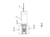
- a first fork-shaped blade-like contact surface 20f of a first plug 22f in the manner of a piggyback plug is plugged, which preferably has a rectangular-shaped housing 24 made of insulator material.
- the bifurcated blade-like second contact surface 20e of a second plug 22e is likewise plugged onto the second conductive contact region 18e of the second insulator element 16e in the manner of a piggyback plug, which likewise preferably has a rectangular-shaped housing 24 made of insulator material.
- the blade or knife-like configuration of the fork-shaped contact surfaces 20f and 20e of the first and second connectors 22f and 22e and their interaction with the associated insulator element 16f, 16e is illustrated in FIG.
- the contact surfaces 20f and 20e of the first and second connectors 22f and 22e are connected to each other for transmission of high-frequency signals via an electrical connection line 26 and a coupling capacitor 28.
- the coupling capacitor 28 is preferably a Y1 or Y2 capacitor, which forms an insulator for the electric current in the event of destruction by overvoltage or the like, so that no inadmissible current flows between the power supply lines 8f and 8e, which are electrically isolated from each other by network separation.
- an additional fuse 30 is incorporated in the first connector 22f, which is preferably integrated into the insulated housing of the associated connector 22 in the same way as the coupling capacitor 28.
- the fuse 30 may be e.g. be a 1 amp fuse.
- one or more further plugs 22d can also be connected to the connecting line 26 if further power supply lines 8 disconnected by grid disconnection are to be connected to the first powerline data transmission device 10 within the network node and are to be supplied via this.
- the first powerline data transmission device 10 may alternatively be electrically conductively connected to the connection line 26 via a further connection line 32 indicated in dashed lines in FIG. 2, wherein the connection of the powerline data transmission device 10 is preferably via a not shown Plug contact takes place.
- This makes it possible to create an independent unit of plugs 22 d-f, which are connected to one another via a common connection line 26, and can be connected in a simple manner to a powerline data transmission device 10.
Landscapes
- Engineering & Computer Science (AREA)
- Power Engineering (AREA)
- Computer Networks & Wireless Communication (AREA)
- Signal Processing (AREA)
- Cable Transmission Systems, Equalization Of Radio And Reduction Of Echo (AREA)
- Dc Digital Transmission (AREA)
- Details Of Connecting Devices For Male And Female Coupling (AREA)
- Coupling Device And Connection With Printed Circuit (AREA)
Claims (17)
- Dispositif pour raccorder un dispositif de transmission de données à ligne de puissance (10) à une première et à une seconde lignes d'alimentation électrique (8f, 8e) dans un noeud de réseau d'un réseau électrique basse tension, la première et la seconde lignes d'alimentation électrique (8f, 8e) étant séparées électriquement d'une phase (L1) conductrice du réseau électrique basse tension par l'enlèvement d'un premier et d'un second fusibles pour courant fort (6) attribués d'un premier et d'un second supports de fusible (4f, 4e) attribués par le biais de la séparation de réseau, et le dispositif de transmission de données à ligne de puissance (10) étant relié de façon électroconductrice à la première ligne d'alimentation électrique (8f),
caractérisé par une première fiche (22f), qui présente une première surface de contact (20f) de type lame et fourchue, qui peut être emboîtée sur une première zone de contact (18f) attribuée d'un élément isolateur (16f) pouvant être inséré dans le premier support de fusible (4f), laquelle est en liaison avec la première ligne d'alimentation électrique (8f) dans l'état inséré, et une seconde fiche (22e), qui présente une seconde surface de contact (20e) qui peut être emboîtée sur une seconde zone de contact (18e) d'un second élément isolateur (16e) pouvant être inséré dans le second support de fusible (4e), laquelle est en liaison électroconductrice avec la seconde ligne d'alimentation électrique (8e) dans l'état inséré, les surfaces de contact (20f, 20e) de la première et de la seconde fiches (22f, 22e) étant reliées entre elles pour la transmission de signaux de haute fréquence au moyen d'une ligne de liaison (26) électrique et d'un condensateur de liaison(28). - Dispositif selon la revendication 1,
caractérisé en ce que
la première surface et la deuxième surfaces de contact (18f, 18e) du premier et du second éléments isolateurs (16f, 16e) ont sensiblement la même forme que la surface de contact d'un fusible pour courant fort (6) pouvant être insérée dans le premier et le second supports de fusible (4f, 4e). - Dispositif selon la revendication 1 ou 2,
caractérisé en ce que
la première fiche (22f) et/ou la seconde fiche (22e) présentent un boîtier (24) isolé. - Dispositif selon les revendications 2 et 3,
caractérisé en ce que
la première et/ou la seconde fiche (22f, 22e) présentent un boîtier (24) disposé sensiblement à angle droit, de sorte qu'elles peuvent être emboîtées à la façon d'une fiche gigogne sur l'élément isolateur (16) attribué. - Dispositif selon l'une quelconque des revendications 3 ou 4,
caractérisé en ce que
le condensateur de liaison (28) est intégré dans le boîtier (24) de la seconde fiche (22f). - Dispositif selon l'une quelconque des revendications précédentes,
caractérisé en ce que
le condensateur de liaison (28) est un condensateur avec la spécification Y1ou Y2, qui forme un isolateur électrique dans le cas d'une destruction. - Dispositif selon l'une quelconque des revendications précédentes,
caractérisé en ce que
la première surface de contact (20f) est reliée en supplément au moyen d'un fusible pour courant faible (30) à la ligne de liaison (26) et au condensateur de liaison (28). - Dispositif selon les revendications 3 et 7,
caractérisé en ce que
le fusible (30) est intégré dans le boîtier (24) de la première fiche (22f). - Dispositif selon l'une quelconque des revendications précédentes,
caractérisé en ce que
le dispositif de transmission de données à ligne de puissance (10) est relié de façon électroconductrice à la première ligne d'alimentation électrique (8f) au moyen d'un élément de contact en forme d'aiguille, traversant l'isolation de la première ligne d'alimentation électrique (8f). - Dispositif selon l'une quelconque des revendications 1 à 8,
caractérisé en ce que
le dispositif de transmission de données à ligne de puissance (10) est relié au moyen d'une autre ligne de liaison (23) de façon électroconductrice à la première surface de contact (20f) de la première fiche (22f). - Dispositif selon l'une quelconque des revendications précédentes,
caractérisé en ce que
une ou plusieurs autres fiches (22d) sont reliées au moyen d'autres condensateurs de liaison (28) attribués de façon électroconductrice à la première surface de contact (20f) de la première fiche (22f), afin de relier une ou d'autres lignes d'alimentation électrique (8c) séparées de la phase (L1) par séparation de réseau au dispositif de transmission de données à ligne de puissance (10). - Procédé pour raccorder un dispositif de transmission de données à ligne de puissance (10) à une première et une seconde lignes d'alimentation électriques (8f, 8e) dans un noeud de réseau d'un réseau électrique à basse tension, la première et la seconde lignes d'alimentation électrique (8f, 8e) étant séparées, par le biais de la séparation de réseau, électriquement d'une phase (L1) conductrice du réseau électrique basse tension, et la phase (L1) conductrice de courant étant reliée de façon électroconductrice à un autre dispositif de transmission de données à ligne de puissance (12),
caractérisé en ce que
le premier dispositif d'alimentation électrique (8f) et la seconde ligne d'alimentation électrique (8e) sont reliées entre elles au moyen d'un condensateur de liaison (28) et d'une ligne de liaison (26) électrique, et le dispositif de transmission de données à ligne de puissance (10) est raccordé de façon électroconductrice à la ligne de liaison (26) électrique. - Procédé selon la revendication 12 précédente,
caractérisé en ce que
la ligne de liaison (26) électrique est reliée par un fusible pour courant faible (30) à la première ligne d'alimentation électrique (8f), et le condensateur de liaison (28) est relié à la seconde ligne d'arrivée électrique (8e) à la ligne d'alimentation (26) électrique pour la transmission de signaux de haute fréquence. - Procédé selon l'une quelconque des revendications 12 ou 13,
caractérisé en ce que
le dispositif de transmission de données à ligne de puissance (10) peut être relié par une première fiche (22f) à la première ligne d'alimentation électrique (8f). - Procédé selon la revendication 14,
caractérisé en ce que
le dispositif de transmission de données à ligne de puissance (10) peut être relié au moyen d'une seconde fiche (22e) à la seconde ligne d'alimentation électrique (8e). - Procédé selon l'une quelconque des revendications 12 à 15,
caractérisé en ce que
le dispositif de transmission de données à ligne de puissance (10) est relié de façon électroconductrice à la première ligne d'alimentation électrique (8f) au moyen d'un élément de contact en forme d'aiguille, traversant l'isolation de la première ligne d'alimentation électrique (8f). - Procédé selon la revendication 16,
caractérisé en ce que
la ligne d'alimentation (26) électrique est reliée à la seconde ligne d'alimentation électrique (8e) avec l'intercalation du condensateur de liaison (28) au moyen d'un élément de contact en forme d'aiguille, traversant l'isolation de la seconde ligne d'alimentation électrique (8e) pour la transmission de signaux de haute fréquence.
Applications Claiming Priority (3)
| Application Number | Priority Date | Filing Date | Title |
|---|---|---|---|
| DE10239016A DE10239016B3 (de) | 2002-08-20 | 2002-08-20 | Anordnung und Verfahren zum Anschluss einer Powerline-Datenübertragungseinrichtung an mehrere Stromversorgungsleitungen |
| DE10239016 | 2002-08-20 | ||
| PCT/EP2003/007625 WO2004021600A1 (fr) | 2002-08-20 | 2003-07-15 | Systeme et procede pour raccorder un dispositif de transmission de donnees sur lignes electriques a plusieurs lignes d'alimentation electrique |
Publications (2)
| Publication Number | Publication Date |
|---|---|
| EP1530833A1 EP1530833A1 (fr) | 2005-05-18 |
| EP1530833B1 true EP1530833B1 (fr) | 2007-06-20 |
Family
ID=31968992
Family Applications (1)
| Application Number | Title | Priority Date | Filing Date |
|---|---|---|---|
| EP03790799A Expired - Lifetime EP1530833B1 (fr) | 2002-08-20 | 2003-07-15 | Systeme et procede pour raccorder un dispositif de transmission de donnees sur lignes electriques a plusieurs lignes d'alimentation electrique |
Country Status (5)
| Country | Link |
|---|---|
| EP (1) | EP1530833B1 (fr) |
| AT (1) | ATE365401T1 (fr) |
| AU (1) | AU2003250948A1 (fr) |
| DE (2) | DE10239016B3 (fr) |
| WO (1) | WO2004021600A1 (fr) |
Families Citing this family (21)
| Publication number | Priority date | Publication date | Assignee | Title |
|---|---|---|---|---|
| US6998962B2 (en) | 2000-04-14 | 2006-02-14 | Current Technologies, Llc | Power line communication apparatus and method of using the same |
| US6965302B2 (en) | 2000-04-14 | 2005-11-15 | Current Technologies, Llc | Power line communication system and method of using the same |
| US7103240B2 (en) | 2001-02-14 | 2006-09-05 | Current Technologies, Llc | Method and apparatus for providing inductive coupling and decoupling of high-frequency, high-bandwidth data signals directly on and off of a high voltage power line |
| US7248148B2 (en) | 2000-08-09 | 2007-07-24 | Current Technologies, Llc | Power line coupling device and method of using the same |
| US7245201B1 (en) | 2000-08-09 | 2007-07-17 | Current Technologies, Llc | Power line coupling device and method of using the same |
| US7053756B2 (en) | 2001-12-21 | 2006-05-30 | Current Technologies, Llc | Facilitating communication of data signals on electric power systems |
| US6982611B2 (en) | 2002-06-24 | 2006-01-03 | Current Technologies, Llc | Power line coupling device and method of using the same |
| US7132819B1 (en) | 2002-11-12 | 2006-11-07 | Current Technologies, Llc | Floating power supply and method of using the same |
| US6965303B2 (en) | 2002-12-10 | 2005-11-15 | Current Technologies, Llc | Power line communication system and method |
| US6980091B2 (en) | 2002-12-10 | 2005-12-27 | Current Technologies, Llc | Power line communication system and method of operating the same |
| US7075414B2 (en) | 2003-05-13 | 2006-07-11 | Current Technologies, Llc | Device and method for communicating data signals through multiple power line conductors |
| US6980090B2 (en) | 2002-12-10 | 2005-12-27 | Current Technologies, Llc | Device and method for coupling with electrical distribution network infrastructure to provide communications |
| US7064654B2 (en) | 2002-12-10 | 2006-06-20 | Current Technologies, Llc | Power line communication system and method of operating the same |
| US7046124B2 (en) | 2003-01-21 | 2006-05-16 | Current Technologies, Llc | Power line coupling device and method of using the same |
| US7113134B1 (en) | 2004-03-12 | 2006-09-26 | Current Technologies, Llc | Transformer antenna device and method of using the same |
| US7307512B2 (en) | 2005-04-29 | 2007-12-11 | Current Technologies, Llc | Power line coupling device and method of use |
| US11316368B2 (en) * | 2007-03-14 | 2022-04-26 | Zonit Structured Solutions, Llc | Premises power usage monitoring system |
| US7795994B2 (en) | 2007-06-26 | 2010-09-14 | Current Technologies, Llc | Power line coupling device and method |
| US7876174B2 (en) | 2007-06-26 | 2011-01-25 | Current Technologies, Llc | Power line coupling device and method |
| JP5446239B2 (ja) * | 2008-12-16 | 2014-03-19 | ソニー株式会社 | 電力供給システム |
| CN102752022B (zh) * | 2012-06-29 | 2014-09-10 | 清华大学深圳研究生院 | 电力线通信方法及其帧响应方法和装置 |
Family Cites Families (7)
| Publication number | Priority date | Publication date | Assignee | Title |
|---|---|---|---|---|
| JP2001509335A (ja) * | 1997-01-28 | 2001-07-10 | ノーテル・ネットワークス・コーポレーション | 電力線伝送 |
| DE50013593D1 (de) * | 1999-08-18 | 2006-11-23 | Siemens Ag | Ankoppeleinheit mit integriertem Steckkontaktbereich zur Ankopplung einer Datenübertragungsvorrichtung an die Phase eines elektrischen Energieübertragungsnetzes |
| DE10019322C2 (de) * | 2000-04-19 | 2003-06-18 | Rundfunkschutzrechte Ev | Vorrichtung zur Konditionierung der elektrischen Gebäudeinstallation für die schnelle Datenübertragung |
| DE10027155A1 (de) * | 2000-05-31 | 2001-12-06 | Efen Elektrotech Fab | Elektrische Ankoppeleinheit für hochfrequente Datenströme |
| DE10044638A1 (de) * | 2000-09-08 | 2002-04-04 | Pfisterer Kontaktsyst Gmbh | Vorichtung zum elektrischen Verbinden einer Datenanschlussleitung mit einer Niederspannungs-Energieversorgungsleitung |
| DE10050476B4 (de) * | 2000-10-12 | 2005-03-31 | IAD Gesellschaft für Informatik, Automatisierung und Datenverarbeitung mbH | Vorrichtung zur Durchführung sowohl von Messungen als auch von Datenübertragung in elektrischen Energieverteilnetzen |
| DE10150226C1 (de) * | 2001-10-12 | 2003-04-30 | Power Plus Communications Ag | Anordnung zum Anschluss einer Powerline-Datenübertragungseinrichtung oder eines Zwischenverstärkers an ein Spannungsführendes Niederspannungs-Stromnetz |
-
2002
- 2002-08-20 DE DE10239016A patent/DE10239016B3/de not_active Expired - Fee Related
-
2003
- 2003-07-15 EP EP03790799A patent/EP1530833B1/fr not_active Expired - Lifetime
- 2003-07-15 AT AT03790799T patent/ATE365401T1/de active
- 2003-07-15 WO PCT/EP2003/007625 patent/WO2004021600A1/fr not_active Ceased
- 2003-07-15 AU AU2003250948A patent/AU2003250948A1/en not_active Abandoned
- 2003-07-15 DE DE50307526T patent/DE50307526D1/de not_active Expired - Lifetime
Non-Patent Citations (1)
| Title |
|---|
| None * |
Also Published As
| Publication number | Publication date |
|---|---|
| DE10239016B3 (de) | 2004-04-08 |
| AU2003250948A1 (en) | 2004-03-19 |
| EP1530833A1 (fr) | 2005-05-18 |
| WO2004021600A1 (fr) | 2004-03-11 |
| DE50307526D1 (de) | 2007-08-02 |
| ATE365401T1 (de) | 2007-07-15 |
Similar Documents
| Publication | Publication Date | Title |
|---|---|---|
| EP1530833B1 (fr) | Systeme et procede pour raccorder un dispositif de transmission de donnees sur lignes electriques a plusieurs lignes d'alimentation electrique | |
| EP1312172B1 (fr) | Procede et dispositif pour la transmission de signaux haute frequence sur des reseaux basse tension | |
| DE69329827T2 (de) | Übertragungsnetzwerk und filter hierfür | |
| DE19934334C1 (de) | Verfahren zum Betreiben von zur Energieverteilung vorgesehenen Niederspannungsnetzen zur Datenübertragung, zugehörige Schaltung und Anordnung mit einer solchen Schaltung | |
| EP1435141B1 (fr) | Systeme de raccordement d'un dispositif de transmission de donnees d'alimentation ou d'un amplificateur intermediaire a un reseau d'alimentation basse tension sous tension | |
| EP1522152B1 (fr) | Systeme de transmission filaire de donnees par un reseau de courant | |
| DE19841864A1 (de) | Koppelkondensator mit integriertem Anschlußkabel | |
| EP1830437A2 (fr) | Contact électrique | |
| DE10120540C1 (de) | Anschluß eines Modems als Einspeisemöglichkeit für Daten bei der leitungsgebundenen Datenübertragung an einer Verteilervorrichtung | |
| EP3701599B1 (fr) | Distributeur de branchements électriques | |
| EP1151552B1 (fr) | Circuit de couplage capacitif d'un dispositif de transmission de donnees a un reseau de transmission d'energie, et unite de couplage comportant un circuit de couplage | |
| WO2017055018A1 (fr) | Système de caméra pour appareillages de connexion à isolation gazeuse | |
| DE102009039024B3 (de) | Datenbus-Verbindungsanordnung und Datenbus-Verbindungsanleitung | |
| EP4115480B1 (fr) | Dispositif ethernet à paire unique, système ethernet à paire unique et procédé d'installation de système ethernet à paire unique | |
| EP0952681A2 (fr) | Cable de couplage capacitif pour coupler des signaux sur des lignes d'alimentation | |
| DE19728500C1 (de) | Datenübertragungssystem zur Übertragung von Daten über wenigstens ein elektrisches Energiekabel | |
| EP3590153A1 (fr) | Module à pont de câbles pour l'interconnexion flexible d'éléments de liaison | |
| EP1649611B1 (fr) | Adaptateur de mesure pour la simulation d'un reseau basse tension couple a un dispositif de transmission de donnees par courants porteurs en ligne | |
| DE4231080C1 (de) | Koaxiales Verzweigungselement zur Verbindung mit einem koaxialen Winkelstecker | |
| DE102006020029A1 (de) | Adaptive, kapazitive Koppelschaltung und Verfahren zur Nachrichtenübertragung über geschirmte Energiekabel eines elektrischen Energieverteilnetzes | |
| WO2001093453A1 (fr) | Unite de couplage electrique pour flux de donnees haute frequence | |
| AT512668B1 (de) | Anordnung zur Übertragung von Daten in einem Stromversorgungsnetz | |
| DE102019102793A1 (de) | Kraftfahrzeugenergieleiteranschluss und Kraftfahrzeugenergieleiter | |
| EP3672150A1 (fr) | Logement de connecteur destiné à la transmission simultanée de données et de tension continue | |
| EP1468504A1 (fr) | Dispositif de couplage |
Legal Events
| Date | Code | Title | Description |
|---|---|---|---|
| PUAI | Public reference made under article 153(3) epc to a published international application that has entered the european phase |
Free format text: ORIGINAL CODE: 0009012 |
|
| 17P | Request for examination filed |
Effective date: 20040501 |
|
| AK | Designated contracting states |
Kind code of ref document: A1 Designated state(s): AT BE BG CH CY CZ DE DK EE ES FI FR GB GR HU IE IT LI LU MC NL PT RO SE SI SK TR |
|
| AX | Request for extension of the european patent |
Extension state: AL LT LV MK |
|
| RIN1 | Information on inventor provided before grant (corrected) |
Inventor name: HEILER, WOLFGANG Inventor name: FLICKER, JUERGEN |
|
| DAX | Request for extension of the european patent (deleted) | ||
| GRAP | Despatch of communication of intention to grant a patent |
Free format text: ORIGINAL CODE: EPIDOSNIGR1 |
|
| GRAS | Grant fee paid |
Free format text: ORIGINAL CODE: EPIDOSNIGR3 |
|
| GRAA | (expected) grant |
Free format text: ORIGINAL CODE: 0009210 |
|
| AK | Designated contracting states |
Kind code of ref document: B1 Designated state(s): AT BE BG CH CY CZ DE DK EE ES FI FR GB GR HU IE IT LI LU MC NL PT RO SE SI SK TR |
|
| REG | Reference to a national code |
Ref country code: GB Ref legal event code: FG4D Free format text: NOT ENGLISH |
|
| REG | Reference to a national code |
Ref country code: CH Ref legal event code: EP |
|
| REG | Reference to a national code |
Ref country code: IE Ref legal event code: FG4D Free format text: LANGUAGE OF EP DOCUMENT: GERMAN |
|
| REG | Reference to a national code |
Ref country code: CH Ref legal event code: NV Representative=s name: SCHMAUDER & PARTNER AG PATENTANWALTSBUERO |
|
| REF | Corresponds to: |
Ref document number: 50307526 Country of ref document: DE Date of ref document: 20070802 Kind code of ref document: P |
|
| GBT | Gb: translation of ep patent filed (gb section 77(6)(a)/1977) |
Effective date: 20070829 |
|
| PG25 | Lapsed in a contracting state [announced via postgrant information from national office to epo] |
Ref country code: SE Free format text: LAPSE BECAUSE OF FAILURE TO SUBMIT A TRANSLATION OF THE DESCRIPTION OR TO PAY THE FEE WITHIN THE PRESCRIBED TIME-LIMIT Effective date: 20070920 |
|
| ET | Fr: translation filed | ||
| NLV1 | Nl: lapsed or annulled due to failure to fulfill the requirements of art. 29p and 29m of the patents act | ||
| REG | Reference to a national code |
Ref country code: IE Ref legal event code: FD4D |
|
| PG25 | Lapsed in a contracting state [announced via postgrant information from national office to epo] |
Ref country code: NL Free format text: LAPSE BECAUSE OF FAILURE TO SUBMIT A TRANSLATION OF THE DESCRIPTION OR TO PAY THE FEE WITHIN THE PRESCRIBED TIME-LIMIT Effective date: 20070620 Ref country code: IE Free format text: LAPSE BECAUSE OF FAILURE TO SUBMIT A TRANSLATION OF THE DESCRIPTION OR TO PAY THE FEE WITHIN THE PRESCRIBED TIME-LIMIT Effective date: 20070620 Ref country code: CZ Free format text: LAPSE BECAUSE OF FAILURE TO SUBMIT A TRANSLATION OF THE DESCRIPTION OR TO PAY THE FEE WITHIN THE PRESCRIBED TIME-LIMIT Effective date: 20070620 Ref country code: SI Free format text: LAPSE BECAUSE OF FAILURE TO SUBMIT A TRANSLATION OF THE DESCRIPTION OR TO PAY THE FEE WITHIN THE PRESCRIBED TIME-LIMIT Effective date: 20070620 Ref country code: ES Free format text: LAPSE BECAUSE OF FAILURE TO SUBMIT A TRANSLATION OF THE DESCRIPTION OR TO PAY THE FEE WITHIN THE PRESCRIBED TIME-LIMIT Effective date: 20071001 Ref country code: PT Free format text: LAPSE BECAUSE OF FAILURE TO SUBMIT A TRANSLATION OF THE DESCRIPTION OR TO PAY THE FEE WITHIN THE PRESCRIBED TIME-LIMIT Effective date: 20071120 Ref country code: BG Free format text: LAPSE BECAUSE OF FAILURE TO SUBMIT A TRANSLATION OF THE DESCRIPTION OR TO PAY THE FEE WITHIN THE PRESCRIBED TIME-LIMIT Effective date: 20070920 |
|
| PG25 | Lapsed in a contracting state [announced via postgrant information from national office to epo] |
Ref country code: SK Free format text: LAPSE BECAUSE OF FAILURE TO SUBMIT A TRANSLATION OF THE DESCRIPTION OR TO PAY THE FEE WITHIN THE PRESCRIBED TIME-LIMIT Effective date: 20070620 |
|
| PLBE | No opposition filed within time limit |
Free format text: ORIGINAL CODE: 0009261 |
|
| STAA | Information on the status of an ep patent application or granted ep patent |
Free format text: STATUS: NO OPPOSITION FILED WITHIN TIME LIMIT |
|
| PG25 | Lapsed in a contracting state [announced via postgrant information from national office to epo] |
Ref country code: GR Free format text: LAPSE BECAUSE OF FAILURE TO SUBMIT A TRANSLATION OF THE DESCRIPTION OR TO PAY THE FEE WITHIN THE PRESCRIBED TIME-LIMIT Effective date: 20070921 Ref country code: IT Free format text: LAPSE BECAUSE OF FAILURE TO SUBMIT A TRANSLATION OF THE DESCRIPTION OR TO PAY THE FEE WITHIN THE PRESCRIBED TIME-LIMIT Effective date: 20070620 Ref country code: DK Free format text: LAPSE BECAUSE OF FAILURE TO SUBMIT A TRANSLATION OF THE DESCRIPTION OR TO PAY THE FEE WITHIN THE PRESCRIBED TIME-LIMIT Effective date: 20070620 Ref country code: MC Free format text: LAPSE BECAUSE OF NON-PAYMENT OF DUE FEES Effective date: 20070731 |
|
| 26N | No opposition filed |
Effective date: 20080325 |
|
| PG25 | Lapsed in a contracting state [announced via postgrant information from national office to epo] |
Ref country code: RO Free format text: LAPSE BECAUSE OF FAILURE TO SUBMIT A TRANSLATION OF THE DESCRIPTION OR TO PAY THE FEE WITHIN THE PRESCRIBED TIME-LIMIT Effective date: 20070620 |
|
| PG25 | Lapsed in a contracting state [announced via postgrant information from national office to epo] |
Ref country code: EE Free format text: LAPSE BECAUSE OF FAILURE TO SUBMIT A TRANSLATION OF THE DESCRIPTION OR TO PAY THE FEE WITHIN THE PRESCRIBED TIME-LIMIT Effective date: 20070620 |
|
| PG25 | Lapsed in a contracting state [announced via postgrant information from national office to epo] |
Ref country code: FI Free format text: LAPSE BECAUSE OF FAILURE TO SUBMIT A TRANSLATION OF THE DESCRIPTION OR TO PAY THE FEE WITHIN THE PRESCRIBED TIME-LIMIT Effective date: 20070620 |
|
| PG25 | Lapsed in a contracting state [announced via postgrant information from national office to epo] |
Ref country code: CY Free format text: LAPSE BECAUSE OF FAILURE TO SUBMIT A TRANSLATION OF THE DESCRIPTION OR TO PAY THE FEE WITHIN THE PRESCRIBED TIME-LIMIT Effective date: 20070620 |
|
| REG | Reference to a national code |
Ref country code: CH Ref legal event code: PCAR Free format text: SCHMAUDER & PARTNER AG PATENT- UND MARKENANWAELTE VSP;ZWAENGIWEG 7;8038 ZUERICH (CH) |
|
| PG25 | Lapsed in a contracting state [announced via postgrant information from national office to epo] |
Ref country code: TR Free format text: LAPSE BECAUSE OF FAILURE TO SUBMIT A TRANSLATION OF THE DESCRIPTION OR TO PAY THE FEE WITHIN THE PRESCRIBED TIME-LIMIT Effective date: 20070620 Ref country code: HU Free format text: LAPSE BECAUSE OF FAILURE TO SUBMIT A TRANSLATION OF THE DESCRIPTION OR TO PAY THE FEE WITHIN THE PRESCRIBED TIME-LIMIT Effective date: 20071221 |
|
| REG | Reference to a national code |
Ref country code: DE Ref legal event code: R082 Ref document number: 50307526 Country of ref document: DE |
|
| REG | Reference to a national code |
Ref country code: FR Ref legal event code: PLFP Year of fee payment: 14 |
|
| REG | Reference to a national code |
Ref country code: FR Ref legal event code: PLFP Year of fee payment: 15 |
|
| REG | Reference to a national code |
Ref country code: FR Ref legal event code: PLFP Year of fee payment: 16 |
|
| PGFP | Annual fee paid to national office [announced via postgrant information from national office to epo] |
Ref country code: LU Payment date: 20180723 Year of fee payment: 16 |
|
| PGFP | Annual fee paid to national office [announced via postgrant information from national office to epo] |
Ref country code: DE Payment date: 20180725 Year of fee payment: 16 Ref country code: FR Payment date: 20180723 Year of fee payment: 16 |
|
| PGFP | Annual fee paid to national office [announced via postgrant information from national office to epo] |
Ref country code: BE Payment date: 20180723 Year of fee payment: 16 Ref country code: GB Payment date: 20180725 Year of fee payment: 16 Ref country code: AT Payment date: 20180719 Year of fee payment: 16 Ref country code: CH Payment date: 20180725 Year of fee payment: 16 |
|
| REG | Reference to a national code |
Ref country code: DE Ref legal event code: R119 Ref document number: 50307526 Country of ref document: DE |
|
| REG | Reference to a national code |
Ref country code: CH Ref legal event code: PL |
|
| REG | Reference to a national code |
Ref country code: AT Ref legal event code: MM01 Ref document number: 365401 Country of ref document: AT Kind code of ref document: T Effective date: 20190715 |
|
| GBPC | Gb: european patent ceased through non-payment of renewal fee |
Effective date: 20190715 |
|
| REG | Reference to a national code |
Ref country code: BE Ref legal event code: MM Effective date: 20190731 |
|
| PG25 | Lapsed in a contracting state [announced via postgrant information from national office to epo] |
Ref country code: GB Free format text: LAPSE BECAUSE OF NON-PAYMENT OF DUE FEES Effective date: 20190715 Ref country code: AT Free format text: LAPSE BECAUSE OF NON-PAYMENT OF DUE FEES Effective date: 20190715 Ref country code: DE Free format text: LAPSE BECAUSE OF NON-PAYMENT OF DUE FEES Effective date: 20200201 |
|
| PG25 | Lapsed in a contracting state [announced via postgrant information from national office to epo] |
Ref country code: LI Free format text: LAPSE BECAUSE OF NON-PAYMENT OF DUE FEES Effective date: 20190731 Ref country code: LU Free format text: LAPSE BECAUSE OF NON-PAYMENT OF DUE FEES Effective date: 20190715 Ref country code: BE Free format text: LAPSE BECAUSE OF NON-PAYMENT OF DUE FEES Effective date: 20190731 Ref country code: CH Free format text: LAPSE BECAUSE OF NON-PAYMENT OF DUE FEES Effective date: 20190731 |
|
| PG25 | Lapsed in a contracting state [announced via postgrant information from national office to epo] |
Ref country code: FR Free format text: LAPSE BECAUSE OF NON-PAYMENT OF DUE FEES Effective date: 20190731 |