EP1530833B1 - Assembly and method for connecting a power line data transmission device to several power supply lines - Google Patents
Assembly and method for connecting a power line data transmission device to several power supply lines Download PDFInfo
- Publication number
- EP1530833B1 EP1530833B1 EP03790799A EP03790799A EP1530833B1 EP 1530833 B1 EP1530833 B1 EP 1530833B1 EP 03790799 A EP03790799 A EP 03790799A EP 03790799 A EP03790799 A EP 03790799A EP 1530833 B1 EP1530833 B1 EP 1530833B1
- Authority
- EP
- European Patent Office
- Prior art keywords
- power supply
- plug
- supply line
- power
- data transmission
- Prior art date
- Legal status (The legal status is an assumption and is not a legal conclusion. Google has not performed a legal analysis and makes no representation as to the accuracy of the status listed.)
- Expired - Lifetime
Links
- 230000005540 biological transmission Effects 0.000 title claims abstract description 45
- 238000000034 method Methods 0.000 title claims description 10
- 239000003990 capacitor Substances 0.000 claims abstract description 20
- 230000008878 coupling Effects 0.000 claims abstract description 17
- 238000010168 coupling process Methods 0.000 claims abstract description 17
- 238000005859 coupling reaction Methods 0.000 claims abstract description 17
- 238000002955 isolation Methods 0.000 claims abstract description 8
- 238000009413 insulation Methods 0.000 claims description 4
- 230000000149 penetrating effect Effects 0.000 claims 3
- 239000012212 insulator Substances 0.000 description 16
- 238000000926 separation method Methods 0.000 description 7
- 238000004891 communication Methods 0.000 description 6
- 239000000463 material Substances 0.000 description 3
- 238000005516 engineering process Methods 0.000 description 2
- RYGMFSIKBFXOCR-UHFFFAOYSA-N Copper Chemical compound [Cu] RYGMFSIKBFXOCR-UHFFFAOYSA-N 0.000 description 1
- 230000002238 attenuated effect Effects 0.000 description 1
- 239000000919 ceramic Substances 0.000 description 1
- 238000006243 chemical reaction Methods 0.000 description 1
- 239000004020 conductor Substances 0.000 description 1
- 229910052802 copper Inorganic materials 0.000 description 1
- 239000010949 copper Substances 0.000 description 1
- 230000006378 damage Effects 0.000 description 1
- 230000005611 electricity Effects 0.000 description 1
- 239000003365 glass fiber Substances 0.000 description 1
- 230000003993 interaction Effects 0.000 description 1
- 230000007935 neutral effect Effects 0.000 description 1
Images


Classifications
-
- H—ELECTRICITY
- H04—ELECTRIC COMMUNICATION TECHNIQUE
- H04B—TRANSMISSION
- H04B3/00—Line transmission systems
- H04B3/54—Systems for transmission via power distribution lines
- H04B3/56—Circuits for coupling, blocking, or by-passing of signals
-
- H—ELECTRICITY
- H04—ELECTRIC COMMUNICATION TECHNIQUE
- H04B—TRANSMISSION
- H04B2203/00—Indexing scheme relating to line transmission systems
- H04B2203/54—Aspects of powerline communications not already covered by H04B3/54 and its subgroups
- H04B2203/5429—Applications for powerline communications
- H04B2203/5445—Local network
-
- H—ELECTRICITY
- H04—ELECTRIC COMMUNICATION TECHNIQUE
- H04B—TRANSMISSION
- H04B2203/00—Indexing scheme relating to line transmission systems
- H04B2203/54—Aspects of powerline communications not already covered by H04B3/54 and its subgroups
- H04B2203/5462—Systems for power line communications
- H04B2203/5466—Systems for power line communications using three phases conductors
-
- H—ELECTRICITY
- H04—ELECTRIC COMMUNICATION TECHNIQUE
- H04B—TRANSMISSION
- H04B2203/00—Indexing scheme relating to line transmission systems
- H04B2203/54—Aspects of powerline communications not already covered by H04B3/54 and its subgroups
- H04B2203/5462—Systems for power line communications
- H04B2203/5483—Systems for power line communications using coupling circuits
Definitions
- the invention relates to an arrangement and a method for connecting a powerline data transmission device to a plurality of separate power supply lines by a network separation in a network node of a meshed low-voltage power network, according to the preamble of claim 1.
- data signals are modulated as high frequency signals in addition to the usual 50 Hz voltage on power lines.
- the levels of the signal voltages used are generally in the range of less than one volt and have frequencies in the range of 1.5 to 30 MHz.
- connection between devices of the Powerline system which are connected in a meshed power network, takes place according to the principles of a data network with a bus as a medium. Since the high-frequency signals are attenuated more and more with increasing distance, the use of repeaters is required, which are referred to in the art as a "repeater”.
- the powerline data transmission devices which are referred to in professional circles as "CU's" (Central Units), are mounted on distribution devices of the so-called low-voltage power grid with voltages of about 230 V, such as transformer stations, street distributors or service boxes, and couple the high frequency Signals in the respective, leading to the individual house connections power supply lines of the low-voltage power grid, which are usually connected via power fuses with one of the current-carrying busbars of the transformer station, the road distributor or house connection.
- CU's Central Units
- a power line communication device forcibly couples its high frequency signals into all the power lines connected to the bus bar due to the electrically conductive connection via the bus bar, so that e.g. in the case of a road distributor in which three or more rows of houses are supplied by a bus, the maximum possible data transmission rate per row of houses is only one third of the maximum transmission rate of the powerline data transmission device. .
- the powerline communication devices in view of the maximum transferable amount of data due to the signal conversion, form the bottleneck in the transmission of the data, whereas the data networks transmitting the data from the server computers to the powerline communication devices have a significantly greater bandwidth, and e.g. are capable of supplying 10 or more powerline communication devices.
- the power lines for supplying the house connections or streets which are connected via associated high-current fuses to the current-conducting busbars within a distribution box, by removing the To separate fuse from the associated busbar, and to provide in a corresponding manner via a distribution box at the other end of the busbar with power, which is usually associated with another mesh of the power grid.
- This process is referred to in professional circles as "network separation”.
- the object of the invention is to provide a cost-effective and reliable option for connecting a powerline data transmission device to two or more power supply lines, which are electrically isolated from each other by network separation.
- an arrangement for connecting a powerlin data transmission device to a first and second power supply line disconnected from a current-conducting phase by a grid node in a grid node of a low voltage power supply comprises a first plug having a first bifurcated blade-like contact surface facing an associated first one Contact region of a first insulator element according to the invention can be plugged, which is inserted into one of the first power supply line associated fuse holder.
- the first contact region is electrically conductively connected to the first power supply line in the inserted state of the insulator element.
- the arrangement according to the invention further comprises a second plug, which has a second, preferably in the same manner as the first contact surface formed contact surface which can be plugged onto a second contact region of a second insulator element, which is inserted into a second, the second power supply line associated fuse holder.
- the second contact area is here used State of the second insulator element electrically conductively connected to the second power supply line.
- the first contact surface of the first connector and the second contact surface of the second connector are interconnected according to the invention via an electrical connection line, such as a double insulated copper cable or a coaxial cable, and a coupling capacitor, wherein the coupling capacitor preferably a Y1-type or Y2-type capacitor is that has such a capacity that the high-frequency signals generated by the powerline data transmission device can pass through the coupling capacitor, but the 50 Hz alternating voltage of the low-voltage power supply is electrically isolated.
- an electrical connection line such as a double insulated copper cable or a coaxial cable
- a coupling capacitor preferably a Y1-type or Y2-type capacitor is that has such a capacity that the high-frequency signals generated by the powerline data transmission device can pass through the coupling capacitor, but the 50 Hz alternating voltage of the low-voltage power supply is electrically isolated.
- the invention provides the advantage that the first and the second power supply line separated from the associated electrically conducting phase within a control box or road distributor or a transformer station via the powerline data transmission device can additionally be supplied with data by the powerline data transmission device be converted into corresponding high-frequency signals, which are coupled via the inventive arrangement in the first and second power supply line.
- the data transmission rate which is generally limited by the powerline data transmission device can advantageously be increased overall by connecting a further powerline data transmission device to the current-carrying phase, which supplies the remaining power supply lines of the network node which are not separated by network isolation.
- a method for connecting a powerline data transmission device to a first and a second power supply line in a network node of a low-voltage power network wherein the first and the second power supply line by electrical isolation of a current-carrying phase of the low-voltage Power supply are separated, and the current-carrying phase with another powerline data transmission device electrically is conductively connected, characterized in that the first power supply line and the second power supply line via a coupling capacitor and an electrical connection line are connected to each other, and the power line data transmission device is electrically connected to the electrical connection line.
- a switch box 2 of a meshed low-voltage power network comprises a total of four busbars, of which the three busbars L1, L2, L3 correspond to the respective phases, and the busbar designated "PEN" corresponds to the combined low-voltage grounding conductor / neutral Power network are assigned.
- the busbars L1, L2, L3 are equipped with fuse holders 4a to 4f, in which heavy-current fuses 6 can be inserted, which electrically conductively connects the respective busbar to the associated power supply line 8a-f.
- the power supply lines 8 a-f supply, for example, the households of a street with electricity, and open with its other end in a not shown another switch box another node of the low-voltage power grid.
- the power supply lines 8d, 8e and 8f are electrically separated by removing the associated fuses 6 from the associated fuse holders 4d, 4e and 4f by means of network separation from the current-carrying busbar L1 and are connected via the switching box, not shown, of the further node of the low voltage Power grid powered from the other end.
- the power supply line 8f is coupled to a first powerline communication device 10, e.g. by way of the piercing technology known in the art, by piercing the insulation of the associated wires for the PEN and the phase associated with the bus bar L1 by acicular elements contacting the live wires to supply the radio frequency signals transfer.
- the busbar L1 is further connected to a further powerline data transmission device 12, which connects the power supply lines 8a, 8b, 8c and the households connected to the data network 14, which is for example a glass fiber network, with a not shown network computer for transmitting the Data is coupled in the form of data packets.
- a further powerline data transmission device 12 which connects the power supply lines 8a, 8b, 8c and the households connected to the data network 14, which is for example a glass fiber network, with a not shown network computer for transmitting the Data is coupled in the form of data packets.
- the further powerline data transmission device 12 converts the data packets supplied to it via the data network 14 into high-frequency signals which are fed directly to the power supply lines 8a, 8b and 8c and via these to the respective consumers as a result of the electrically conductive connection between the busbar L1 and the high-current fuses 6 ,
- fuse holders 4f and 4e employ first and second insulator elements 16f and 16e, each comprising a body of insulator material, e.g. of ceramic, on which an associated first and second contact region 18f and 18e is formed, which is in electrically inserted connection with the insulator element 16 inserted with the associated first or second power supply line 8f, 8e.
- first and second insulator elements 16f and 16e each comprising a body of insulator material, e.g. of ceramic, on which an associated first and second contact region 18f and 18e is formed, which is in electrically inserted connection with the insulator element 16 inserted with the associated first or second power supply line 8f, 8e.
- additional insulator elements 16 can be inserted into the associated fuse holders 4 for connecting additional power supply lines separated by network isolation, as is indicated by way of example with reference to the fuse holder 4d and the insulator element 16d.
- a first fork-shaped blade-like contact surface 20f of a first plug 22f in the manner of a piggyback plug is plugged, which preferably has a rectangular-shaped housing 24 made of insulator material.
- the bifurcated blade-like second contact surface 20e of a second plug 22e is likewise plugged onto the second conductive contact region 18e of the second insulator element 16e in the manner of a piggyback plug, which likewise preferably has a rectangular-shaped housing 24 made of insulator material.
- the blade or knife-like configuration of the fork-shaped contact surfaces 20f and 20e of the first and second connectors 22f and 22e and their interaction with the associated insulator element 16f, 16e is illustrated in FIG.
- the contact surfaces 20f and 20e of the first and second connectors 22f and 22e are connected to each other for transmission of high-frequency signals via an electrical connection line 26 and a coupling capacitor 28.
- the coupling capacitor 28 is preferably a Y1 or Y2 capacitor, which forms an insulator for the electric current in the event of destruction by overvoltage or the like, so that no inadmissible current flows between the power supply lines 8f and 8e, which are electrically isolated from each other by network separation.
- an additional fuse 30 is incorporated in the first connector 22f, which is preferably integrated into the insulated housing of the associated connector 22 in the same way as the coupling capacitor 28.
- the fuse 30 may be e.g. be a 1 amp fuse.
- one or more further plugs 22d can also be connected to the connecting line 26 if further power supply lines 8 disconnected by grid disconnection are to be connected to the first powerline data transmission device 10 within the network node and are to be supplied via this.
- the first powerline data transmission device 10 may alternatively be electrically conductively connected to the connection line 26 via a further connection line 32 indicated in dashed lines in FIG. 2, wherein the connection of the powerline data transmission device 10 is preferably via a not shown Plug contact takes place.
- This makes it possible to create an independent unit of plugs 22 d-f, which are connected to one another via a common connection line 26, and can be connected in a simple manner to a powerline data transmission device 10.
Landscapes
- Engineering & Computer Science (AREA)
- Power Engineering (AREA)
- Computer Networks & Wireless Communication (AREA)
- Signal Processing (AREA)
- Cable Transmission Systems, Equalization Of Radio And Reduction Of Echo (AREA)
- Dc Digital Transmission (AREA)
- Details Of Connecting Devices For Male And Female Coupling (AREA)
- Coupling Device And Connection With Printed Circuit (AREA)
Abstract
Description
Die Erfindung betrifft eine Anordnung und ein Verfahren zum Anschluss einer Powerline-Datenübertragungseinrichtung an mehrere, durch eine Netztrennung voneinander getrennte Stromversorgungsleitungen in einem Netzknoten eines vermaschten Niederspannungs-Stromnetzes, gemäß dem Oberbegriff von Anspruch 1.The invention relates to an arrangement and a method for connecting a powerline data transmission device to a plurality of separate power supply lines by a network separation in a network node of a meshed low-voltage power network, according to the preamble of
Auf dem Gebiet der Telekommunikation werden heutzutage für die Übertragung von elektronischen Daten zwischen Rechnern, beispielsweise im Bereich des Internets, neben speziell für diese Zwecke ausgebildeten herkömmlichen Datenleitungen in zunehmendem Maße die Leitungen des öffentlichen Stromnetzes verwendet.In the field of telecommunications, the transmission of electronic data between computers, for example in the area of the Internet, in addition to specially designed for this purpose conventional data lines increasingly the lines of the public power grid are nowadays used.
Bei dieser in Fachkreisen als "Powerline" System oder "Powerline Communications" (PLC) bezeichneten Technologie werden Datensignale neben der üblichen 50 Hz Spannung auf Stromleitungen als Hochfrequenzsignale aufmoduliert. Hierbei liegen die Pegel der verwendeten Signalspannungen in der Regel im Bereich von weniger als einem Volt und weisen Frequenzen im Bereich von 1,5 bis 30 MHz auf.Called "powerline" or "powerline communications" (PLC) technology, data signals are modulated as high frequency signals in addition to the usual 50 Hz voltage on power lines. In this case, the levels of the signal voltages used are generally in the range of less than one volt and have frequencies in the range of 1.5 to 30 MHz.
Die Verbindung zwischen Geräten des Powerline-Systems, die in einem vermaschten Stromnetz angeschlossen sind, erfolgt dabei nach den Prinzipien eines Datennetzes mit einem Bus als Medium. Da die hochfrequenten Signale mit zunehmender Entfernung mehr und mehr gedämpft werden, ist der Einsatz von Zwischenverstärkern erforderlich, die in Fachkreisen auch als "Repeater" bezeichnet werden.The connection between devices of the Powerline system, which are connected in a meshed power network, takes place according to the principles of a data network with a bus as a medium. Since the high-frequency signals are attenuated more and more with increasing distance, the use of repeaters is required, which are referred to in the art as a "repeater".
Die Powerline-Datenübertragungseinrichtungen, die in Fachkreisen auch als "CU's" (Central Units) bezeichnet werden, werden dabei an Verteilervorrichtungen des sogenannten Niederspannungs-Stromnetzes mit Spannungen von ca. 230 V, wie z.B. Trafostationen, Straßenverteilern oder Hausanschlusskästen, angebracht, und koppeln die hochfrequenten Signale in die jeweiligen, zu den einzelnen Hausanschlüssen führenden Stromversorgungsleitungen des Niederspannungs-Stromnetzes ein, die in der Regel über Starkstromsicherungen mit einer der stromführenden Sammelschienen der Trafostation, des Straßenverteilers oder Hausanschlusses verbunden sind.The powerline data transmission devices, which are referred to in professional circles as "CU's" (Central Units), are mounted on distribution devices of the so-called low-voltage power grid with voltages of about 230 V, such as transformer stations, street distributors or service boxes, and couple the high frequency Signals in the respective, leading to the individual house connections power supply lines of the low-voltage power grid, which are usually connected via power fuses with one of the current-carrying busbars of the transformer station, the road distributor or house connection.
In diesem Zusammenhang ergibt sich das Problem, dass eine Powerline-Datenübertragungseinrichtung aufgrund der elektrisch leitenden Verbindung über die Sammelschiene ihre Hochfrequenzsignale zwangsweise in alle mit der Sammelschiene verbundene Starkstromleitungen einkoppelt, sodass z.B. im Falle eines Straßenverteilers, bei dem drei oder mehrere Häuserreihen durch eine Sammelschiene versorgt werden, die maximal mögliche Datenübertragungsrate pro Häuserreihe lediglich ein Drittel der maximalen Übertragungsrate der Powerline-Datenübertragungseinrichtung beträgt. ,In this connection, there arises a problem that a power line communication device forcibly couples its high frequency signals into all the power lines connected to the bus bar due to the electrically conductive connection via the bus bar, so that e.g. in the case of a road distributor in which three or more rows of houses are supplied by a bus, the maximum possible data transmission rate per row of houses is only one third of the maximum transmission rate of the powerline data transmission device. .
Hierbei bilden die Powerline-Datenübertragungseinrichtungen in Hinblick auf die maximal übertragbare Datenmenge aufgrund der Signalwandlung den Flaschenhals bei der Übertragung der Daten, wohingegen die Datennetze, die die Daten von den Serverrechnern zu den Powerline-Datenübertragungseinrichtunngen übertragen, eine erheblich größere Bandbreite besitzen, und z.B. zur Versorgung von 10 oder mehr Powerline-Datenübertragungseinrichtungen in der Lage sind.Here, the powerline communication devices, in view of the maximum transferable amount of data due to the signal conversion, form the bottleneck in the transmission of the data, whereas the data networks transmitting the data from the server computers to the powerline communication devices have a significantly greater bandwidth, and e.g. are capable of supplying 10 or more powerline communication devices.
In der Praxis ist es weiterhin aus Gründen einer optimalen Anpassung der Ströme innerhalb der einzelnen Maschen eines vermaschten Niederspannungs-Stromnetzes bekannt, die Starkstromleitungen zur Versorgung der Hausanschlüsse oder Straßenzüge, die über zugehörige Starkstromsicherungen an die stromleitenden Sammelschienen innerhalb eines Verteilerkastens angeschlossen sind, durch Entfernen der Sicherung von der zugehörigen Sammelschiene zu trennen, und in entsprechender Weise über einen Verteilerkasten am anderen Ende der Sammelschiene mit Strom zu versorgen, der in der Regel einer anderen Masche des Stromnetzes zugeordnet ist. Dieser Vorgang wird in Fachkreisen auch als "Netztrennung" bezeichnet.In practice, it is also known for reasons of optimal matching of the currents within the individual meshes of a meshed low-voltage power network, the power lines for supplying the house connections or streets, which are connected via associated high-current fuses to the current-conducting busbars within a distribution box, by removing the To separate fuse from the associated busbar, and to provide in a corresponding manner via a distribution box at the other end of the busbar with power, which is usually associated with another mesh of the power grid. This process is referred to in professional circles as "network separation".
Aus der
Durch die Erfindung soll die Aufgabe gelöst werden, eine kostengünstige und zuverlässige Möglichkeit zu schaffen, eine Powerline-Datenübertragungseinrichtung an zwei oder mehrere Stromversorgungsleitungen anzuschließen, die durch Netztrennung elektrisch voneinander getrennt sind.The object of the invention is to provide a cost-effective and reliable option for connecting a powerline data transmission device to two or more power supply lines, which are electrically isolated from each other by network separation.
Diese Aufgabe wird erfindungsgemäß durch die Merkmale von Anspruch 1 gelöst.This object is achieved by the features of
Weitere Merkmale der Erfindung sind in den Unteransprüchen enthalten.Further features of the invention are contained in the subclaims.
Gemäß der Erfindung umfasst eine Anordnung zum Anschluss einer Powerlin-Datenübertragungseinrichtung an eine erste und zweite, durch Netztrennung in einem Netzknoten eines Niederspannungs-Stromnetzes von einer stromleitenden Phase getrennte Stromversorgungsleitung einen ersten Stecker, der eine erste gegabelte klingenartige Kontaktfläche aufweist, die auf einen zugeordneten ersten Kontaktbereich eines ersten erfindungsgemäßen Isolatorelements aufsteckbar ist, welches in eine der ersten Stromversorgungsleitung zugeordnete Sicherungshalterung eingesetzt ist. Der erste Kontaktbereich ist hierbei im eingesetzten Zustand des Isolatorelements elektrisch leitend mit der ersten Stromversorgungsleitung verbunden.According to the invention, an arrangement for connecting a powerlin data transmission device to a first and second power supply line disconnected from a current-conducting phase by a grid node in a grid node of a low voltage power supply comprises a first plug having a first bifurcated blade-like contact surface facing an associated first one Contact region of a first insulator element according to the invention can be plugged, which is inserted into one of the first power supply line associated fuse holder. In this case, the first contact region is electrically conductively connected to the first power supply line in the inserted state of the insulator element.
Die erfindungsgemäße Anordnung umfasst weiterhin einen zweiten Stecker, der eine zweite, vorzugsweise in gleicher Weise wie die erste Kontaktfläche ausgebildete Kontaktfläche aufweist, die auf einen zweiten Kontaktbereich eines zweiten Isolatorelements aufgesteckt werden kann, welches in eine zweite, der zweiten Stromversorgungsleitung zugeordnete Sicherungshalterung eingesteckt ist. Der zweite Kontaktbereich steht hierbei im eingesetzten Zustand des zweiten Isolatorelements elektrisch leitend mit der zweiten Stromversorgungsleitung in Verbindung.The arrangement according to the invention further comprises a second plug, which has a second, preferably in the same manner as the first contact surface formed contact surface which can be plugged onto a second contact region of a second insulator element, which is inserted into a second, the second power supply line associated fuse holder. The second contact area is here used State of the second insulator element electrically conductively connected to the second power supply line.
Die erste Kontaktfläche des ersten Steckers und die zweite Kontaktfläche des zweiten Steckers sind in erfindungsgemäßer Weise über eine elektrische Verbindungsleitung, beispielsweise ein doppelt isoliertes Kupferkabel oder ein Koaxialkabel, sowie einen Koppelkondensator miteinander verbunden, wobei der Koppelkondensator vorzugsweise ein Y1-Typ oder Y2-Typ Kondensator ist, der eine solche Kapazität aufweist, dass die durch die Powerline-Datenübertragungseinrichtung erzeugten Hochfrequenzsignale durch den Koppelkondensator hindurchtreten können, die 50 Hz Wechselspannung des Niederspannungs-Stromnetzes jedoch elektrisch getrennt ist.The first contact surface of the first connector and the second contact surface of the second connector are interconnected according to the invention via an electrical connection line, such as a double insulated copper cable or a coaxial cable, and a coupling capacitor, wherein the coupling capacitor preferably a Y1-type or Y2-type capacitor is that has such a capacity that the high-frequency signals generated by the powerline data transmission device can pass through the coupling capacitor, but the 50 Hz alternating voltage of the low-voltage power supply is electrically isolated.
Durch die Erfindung ergibt sich der Vorteil, dass sich die erste und die zweite, durch Netztrennung von der zugehörigen stromleitenden Phase innerhalb eines Schaltkastens oder Straßenverteilers oder einer Trafostation getrennte Stromversorgungsleitung über die Powerline-Datenübertragungseinrichtung zusätzlich mit Daten versorgen lassen, die durch die Powerline-Datenübertragungseinrichtung in entsprechende Hochfrequenzsignale gewandelt werden, welche über die erfindungsgemäße Anordnung in die erste und zweite Stromversorgungsleitung eingekoppelt werden.The invention provides the advantage that the first and the second power supply line separated from the associated electrically conducting phase within a control box or road distributor or a transformer station via the powerline data transmission device can additionally be supplied with data by the powerline data transmission device be converted into corresponding high-frequency signals, which are coupled via the inventive arrangement in the first and second power supply line.
Zusätzlich hierzu kann die allgemein durch die Powerline-Datenübertragungseinrichtung nach oben hin begrenzte Datenübertragungsrate in vorteilhafter Weise insgesamt dadurch erhöht werden, dass eine weitere Powerline-Datenübertragungseinrichtung an die stromführende Phase angeschlossen wird, die die übrigen, nicht durch Netztrennung getrennten Stromversorgungsleitungen des Netzknotens versorgt.In addition to this, the data transmission rate which is generally limited by the powerline data transmission device can advantageously be increased overall by connecting a further powerline data transmission device to the current-carrying phase, which supplies the remaining power supply lines of the network node which are not separated by network isolation.
Gemäß einer weiteren Ausführungsform der Erfindung zeichnet sich ein Verfahren zum Anschluss einer Powerline-Datenübertragungseinrichtung an eine erste und eine zweite Stromversorgungsleitung in einem Netzknoten eines Niederspannungs-Stromnetzes, wobei die erste und die zweite Stromversorgungsleitung im Wege der Netztrennung elektrisch von einer stromführenden Phase des Niederspannungs-Stromnetzes getrennt sind, und die stromführende Phase mit einer weiteren Powerline-Datenübertragungseinrichtung elektrisch leitend verbunden ist, dadurch aus, dass die erste Stromversorgungsleitung und die zweite Stromversorgungsleitung über einen Koppelkondensator sowie eine elektrische Verbindungsleitung miteinander verbunden sind, und die Powerline-Datenübertragungseinrichtung elektrisch leitend an die elektrische Verbindungsleitung angeschlossen ist. Hierdurch ergibt sich der Vorteil, dass zusätzliche Powerline-Datenübertragungseinrichtungen auf einfachste Weise z.B. durch das zuvor beschriebene sogenanntes "Piercing" direkt an die jeweiligen, durch Netztrennung getrennten Stromversorgungsleitungen angeschlossen werden können, um die Daten-Übertragungskapazitäten weiter zu erhöhen.According to a further embodiment of the invention, a method for connecting a powerline data transmission device to a first and a second power supply line in a network node of a low-voltage power network, wherein the first and the second power supply line by electrical isolation of a current-carrying phase of the low-voltage Power supply are separated, and the current-carrying phase with another powerline data transmission device electrically is conductively connected, characterized in that the first power supply line and the second power supply line via a coupling capacitor and an electrical connection line are connected to each other, and the power line data transmission device is electrically connected to the electrical connection line. This results in the advantage that additional powerline data transmission devices can be connected in the simplest manner, for example by the so-called "piercing" described above, directly to the respective power supply lines separated by network isolation in order to further increase the data transmission capacities.
Die Erfindung wird nachfolgend in Bezug auf die Zeichnungen anhand bevorzugter Ausführungsformen beschrieben.The invention will be described below with reference to the drawings based on preferred embodiments.
In Zeichnung zeigen:
- Fig. 1
- Eine schematische Darstellung eines Schaltkastens eines Netzknotens, bei dem insgesamt drei Stromversorgungsleitungen durch Netztrennung von der stromführenden Phase getrennt, und über eine erfindungsgemäße Anordnung mit einer ersten Powerline-Datenübertragungseinrichtung gekoppelt sind, und die übrigen Stromversorgungsleitungen über eine zweite Powerline-Datenübertragungseinrichtung mit Daten versorgt werden,
- Fig. 2
- eine schematisierte Detaildarstellung der drei durch Netzwerktrennung voneinander getrennten Stromversorgungsleitungen, und
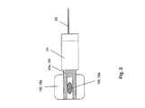
- Fig.3
- eine schematische Darstellung des auf ein Isolatorelement aufgesteckten Steckers zur Verdeutlichung des gegabelten klingenförmigen Kontaktbereichs.
- Fig. 1
- A schematic representation of a control box of a network node, in which a total of three power supply lines separated by power separation from the current-carrying phase, and coupled via an inventive arrangement with a first powerline data transmission device, and the remaining power supply lines are supplied via a second powerline data transmission device with data,
- Fig. 2
- a schematic detail of the three separated by network separation power supply lines, and
- Figure 3
- a schematic representation of the plugged onto an insulator connector plug to illustrate the forked blade-shaped contact area.
Wie in Fig. 1 gezeigt ist, umfasst ein Schaltkasten 2 eines vermaschten Niederspannungs-Stromnetzes insgesamt vier Sammelschienen, von denen die drei Sammelschienen L1, L2, L3 den jeweiligen Phasen, und die mit "PEN" bezeichnete Sammelschiene dem kombinierten Schutzleiter/Nullleiter des Niederspannungs-Stromnetzes zugeordnet sind.As shown in Fig. 1, a
Wie der Fig. 1 weiterhin entnommen werden kann, sind die Sammelschienen L1, L2, L3 mit Sicherungshalterungen 4a bis 4f bestückt, in die Starkstromsicherungen 6 einsetzbar sind, sind, welche die jeweilige Sammelschiene mit der zugehörigen Stromversorgungsleitung 8a-f elektrisch leitend verbindet. Die Stromversorgungsleitungen 8 a-f versorgen hierbei beispielsweise die Haushalte eines Straßenzuges mit Strom, und münden mit ihrem anderen Ende in einen nicht dargestellten weiteren Schaltkasten eines anderen Knotens des Niederspannungs-Stromnetzes.1, the busbars L1, L2, L3 are equipped with
Gemäß Fig. 1 sind die Stromversorgungsleitungen 8d, 8e und 8f durch Entfernen der zugehörigen Sicherungen 6 aus den zugeordneten Sicherungshalterungen 4d, 4e und 4f im Wege der Netztrennung von der stromführenden Sammelschiene L1 elektrisch getrennt und werden über den nicht dargestellten Schaltkasten des weiteren Knotenpunkts des Niederspannungs-Stromnetzes vom anderen Ende aus mit Strom versorgt.According to Fig. 1, the
Die Stromversorgungsleitung 8f ist mit einer ersten Powerline-Datenübertragungseinrichtung 10 gekoppelt, was z.B. im Wege der im Stand der Technik bekannten "Piercing'"-Technologie dadurch erfolgen kann, dass die Isolation der zugehörigen Adern für den PEN sowie die der Sammelschiene L1 zugeordneten Phase durch nadelförmige Elemente durchstochen werden, die die spannungsführenden Adern kontaktieren, um die Hochfrequenzsignale zu übertragen.The
Die Sammelschiene L1 ist ferner mit einer weiteren Powerline-Datenübertragungseinrichtung 12 verbunden, welche die Stromversorgungsleitungen 8a, 8b, 8c und die daran angeschlossenen Haushalte mit dem Datennetz 14 verbindet, welches beispielsweise ein Glasfasernetz ist, das mit einem nicht dargestellten Netzwerk-Rechner zur Übertragung der Daten in Form von Datenpaketen gekoppelt ist.The busbar L1 is further connected to a further powerline
Die weitere Powerline-Datenübertragungseinrichtung 12 wandelt die ihr über das Datennetz 14 zugeführten Datenpakete in Hochfrequenzsignale um, die in Folge der elektrisch leitenden Verbindung zwischen der Sammelschiene L1 und den Starkstromsicherungen 6 den Stromversorgungsleitungen 8a, 8b und 8c und über diese den jeweiligen Verbrauchern direkt zugeführt werden.The further powerline
Wie der Fig. 2 im Detail entnommen werden kann, sind in die Sicherungshalterungen 4f und 4e ein erstes und ein zweites Isolatorelement 16f und 16e eingesetzt, die jeweils einen Körper aus Isolatormaterial, z.B. aus Keramik aufweisen, an welchem ein zugehöriger erster und zweiter Kontaktbereich 18f und 18e gebildet ist, der bei eingesetztem Isolatorelement 16 mit der zugehörigen ersten oder zweiten Stromversorgungsleitung 8f, 8e in elektrisch leitender Verbindung steht.As can be seen in detail in Figure 2,
Gemäß der Darstellung von Fig. 2 können zum Anschluss zusätzlicher, durch Netztrennung getrennter Stromversorgungsleitungen weitere erfindungsgemäße Isolatorelemente 16 in die zugehörigen Sicherungshalterungen 4 eingesetzt sein, wie dies anhand der Sicherungshalterung 4d und des Isolatorelements 16d beispielhaft angedeutet ist.According to the illustration of FIG. 2, additional insulator elements 16 according to the invention can be inserted into the associated fuse holders 4 for connecting additional power supply lines separated by network isolation, as is indicated by way of example with reference to the
Auf den ersten leitenden Kontaktbereich 18f des ersten Isolatorelements 16f ist eine erste gabelförmig ausgebildete klingenartige Kontaktfläche 20f eines ersten Steckers 22f nach Art eines Huckepacksteckers aufgesteckt, der vorzugsweise ein rechtwinklig geformtes Gehäuse 24 aus Isolatormaterial aufweist.On the first
In gleicher Weise ist auf den zweiten leitenden Kontaktbereich 18e des zweiten Isolatorelements 16e die gabelförmig ausgebildete klingenartige zweite Kontaktfläche 20e eines zweiten Steckers 22e ebenfalls nach Art eines Huckepacksteckers aufgesteckt, der vorzugsweise ebenfalls ein rechtwinklig geformtes Gehäuse 24 aus Isolatormaterial aufweist.In the same way, the bifurcated blade-like
Die klingen- oder messerartige Ausgestaltung der gabelförmig ausgebildeten Kontaktflächen 20f und 20e des ersten und zweiten Steckers 22f und 22e und deren Zusammenwirken mit dem zugehörigen Isolatorelement 16f, 16e ist in Fig. 3 verdeutlicht.
Die Kontaktflächen 20f und 20e des ersten und zweiten Steckers 22f und 22e sind zur Übertragung von Hochfrequenzsignalen über eine elektrische Verbindungsleitung 26 und einen Koppelkondensator 28 miteinander verbunden. Der Koppelkondensator 28 ist vorzugsweise ein Y1- oder Y2 Kondensator, der im Falle einer Zerstörung durch Überspannung oder dergleichen, einen Isolator für den elektrischen Strom bildet, so dass zwischen den durch Netztrennung elektrisch voneinander isolierten Stromversorgungsleitungen 8f und 8e kein unzulässiger Strom fließt.The blade or knife-like configuration of the fork-
The
Wie der Darstellung von Fig. 2 weiterhin entnommen werden kann, ist in den ersten Stecker 22f eine zusätzliche Sicherung 30 eingebaut, die in gleicher Weise wie der Koppelkondensator 28 vorzugsweise in das isolierte Gehäuse des zugehörigen Steckers 22 integriert ist. Durch den Einsatz einer Sicherung 30 anstelle eines Koppelkondensators, der in diesem Falle ebenfalls zum Einsatz gelangen könnte, kann der Verlust bei der Übertragung der Hochfrequenzsignale von der ersten Powerline-Datenüberteiseinrichtung 10 in vorteilhafter Weise reduziert werden. Die Sicherung 30 kann z.B. eine 1-Ampere-Sicherung sein.As can further be seen in the illustration of FIG. 2, an
Gemäß der Darstellung von Fig. 2 können an die Verbindungsleitung 26 ferner ein oder auch mehrere weitere Stecker 22d angeschlossen sein, falls weitere, durch Netztrennung abgekoppelte Stromversorgungsleitungen 8 innerhalb des Netzknotens mit der ersten Powerline-Datenübertragungseinrichtung 10 verbunden, und über diese versorgt werden sollen.According to the illustration of FIG. 2, one or more
Gemäß einer weiteren Ausführungsform der Erfindung, kann die erste Powerline-Datenübertragungseinrichtung 10 alternativ über eine in gestrichelten Linien in Fig. 2 angedeutete weitere Verbindungsleitung 32 elektrisch leitend mit der Verbindungsleitung 26 verbunden sein, wobei der Anschluss der Powerline-Datenübertragungseinrichtung 10 vorzugsweise über einen nicht dargestellten Steckkontakt erfolgt. Hierdurch lässt sich eine unabhängige Einheit aus Steckern 22 d-f schaffen, die über eine gemeinsame Verbindungsleitung 26 miteinander verbunden sind, und sich auf einfache Weise an eine Powerline-Datenübertragungseinrichtung 10 anschließen lassen.According to a further embodiment of the invention, the first powerline
Claims (17)
- Assembly for connecting a power line data transmission device (10) to a first and a second power supply line (8f, 8e) in a network node of a low-voltage power network, the first and the second power supply lines (8f, 8e) being electrically isolated from a current conducting phase (L1) of the low voltage network by the removal of an associated first and second power current fuse (6) from an associated first and second fuse holder (4f, 4e), according to the practice of supply isolation, and the power line data transmission device (10) being connected in an electrically conductive manner to the first power supply line (8f), characterised by a first plug (22f) which has a first forked blade-type contact surface (20f) which can be plugged onto a first associated contact region (18f) of an isolator element (16f) which can be inserted into the first fuse holder (4f), which first plug, once inserted, is connected to the first power supply line (8f), and also a second plug (22e) which has a second contact surface (20e) which can be plugged onto a second contact region (18e) of a second isolator element (16e) which can be inserted into the second fuse holder (4e), which second plug, once inserted, is connected in an electrically conductive manner to the second power supply line (8e), the contact surfaces (20f, 20e) of the first and second plugs (22f, 22e) being interconnected in order to transmit high-frequency signals via an electric connecting cable (26) and a coupling capacitor (28).
- Assembly according to claim 1, characterised in that the first and second contact surfaces (18f, 18e) of the first and second isolator elements (16f, 16e) are substantially the same shape as the contact surface of a power current fuse (6) which may be inserted into the first and second fuse holders (4f, 4e).
- Assembly according to either claim 1 or claim 2, characterised in that the first plug (22f) and/or the second plug (22e) has/have an insulated housing (24).
- Assembly according to claims 2 and 3, characterised in that the first and/or second plug (22f, 22e) has/have a housing (24) positioned substantially at a right angle, so that they may be attached onto the associated isolator element (16) in the manner of a piggyback plug.
- Assembly according to either claim 3 or claim 4, characterised in that the coupling capacitor (28) is integrated into the housing (24) of the second plug (22f).
- Assembly according to any one of the preceding claims, characterised in that the coupling capacitor (28) is a capacitor with Y1 or Y2 specification which, in the event of a disruption, forms an electrical isolator.
- Assembly according to any one of the preceding claims, characterised in that the first contact surface (20f) is also connected to the connecting cable (26) and the coupling capacitor (28) via a light current fuse (30).
- Assembly according to claims 3 and 7, characterised in that the fuse (30) is integrated into the housing (24) of the first plug (22f).
- Assembly according to any one of the preceding claims, characterised in that the power line data transmission device (10) is connected in an electrically conductive manner to the first power supply line (8f) via a needle-shaped contact element penetrating the insulation of the first power supply line (8f).
- Assembly according to any one of claims 1 to 8, characterised in that the power line data transmission device (10) is connected in an electrically conductive manner to the first contact surface (20f) of the first plug (22f) via another connecting cable (23).
- Assembly according to any one of the preceding claims, characterised in that one or more other plugs (22d) are connected in an electrically conductive manner to the first contact surface (20f) of the first plug (22f) via other associated coupling capacitors (28) to connect one or more power supply lines (8c), isolated by supply isolation from the phase (L1), to the power line data transmission device (10).
- Method for connecting a power line data transmission device (10) to a first and a second power supply line (8f, 8e) in a network node of a low-voltage power network, the first and the second power supply lines (8f, 8e) being electrically isolated from a current-conducting phase (L1) of the low-voltage network according to the practice of supply isolation, and the current-conducting phase (L1) being connected in an electrically conductive manner to another power line data transmission device (12), characterised in that the first power supply line (8f) and the second power supply line (8e) are interconnected via a coupling capacitor (28) and an electric connecting cable (26), and the power line data transmission device (10) is connected in an electrically conductive manner to the electric connecting cable (26).
- Method according to the preceding claim 12, characterised in that the electric connecting cable (26) is connected to the first power supply line (8f) via a light current fuse (30), and the coupling capacitor (28) connects the second power supply line (8e) to the electric connecting cable (26) to transmit high-frequency signals.
- Method according to either claim 12 or claim 13, characterised in that the power line data transmission device (10) may be connected to the first power supply line (8f) via a first plug (22f).
- Method according to claim 14, characterised in that the power line data transmission device (10) may be connected to the second power supply line (8e) via a second plug (22e).
- Method according to any one of claims 12 to 15, characterised in that the power line data transmission device (10) is connected in an electrically conductive manner to the first power supply line (8f) via a needle-shaped contact element penetrating the insulation of the first power supply line (8f).
- Method according to claim 16, characterised in that the electric connecting cable (26) is connected to the second power supply line (8e) via a needle-shaped contact element, penetrating the insulation of the second power supply line (8e), to transfer high-frequency signals, with the interconnection of the coupling capacitor (28).
Applications Claiming Priority (3)
| Application Number | Priority Date | Filing Date | Title |
|---|---|---|---|
| DE10239016A DE10239016B3 (en) | 2002-08-20 | 2002-08-20 | Arrangement and method for connecting a Powerline data transmission device to several power supply lines |
| DE10239016 | 2002-08-20 | ||
| PCT/EP2003/007625 WO2004021600A1 (en) | 2002-08-20 | 2003-07-15 | Assembly and method for connecting a power line data transmission device to several power supply lines |
Publications (2)
| Publication Number | Publication Date |
|---|---|
| EP1530833A1 EP1530833A1 (en) | 2005-05-18 |
| EP1530833B1 true EP1530833B1 (en) | 2007-06-20 |
Family
ID=31968992
Family Applications (1)
| Application Number | Title | Priority Date | Filing Date |
|---|---|---|---|
| EP03790799A Expired - Lifetime EP1530833B1 (en) | 2002-08-20 | 2003-07-15 | Assembly and method for connecting a power line data transmission device to several power supply lines |
Country Status (5)
| Country | Link |
|---|---|
| EP (1) | EP1530833B1 (en) |
| AT (1) | ATE365401T1 (en) |
| AU (1) | AU2003250948A1 (en) |
| DE (2) | DE10239016B3 (en) |
| WO (1) | WO2004021600A1 (en) |
Families Citing this family (21)
| Publication number | Priority date | Publication date | Assignee | Title |
|---|---|---|---|---|
| US6998962B2 (en) | 2000-04-14 | 2006-02-14 | Current Technologies, Llc | Power line communication apparatus and method of using the same |
| US6965302B2 (en) | 2000-04-14 | 2005-11-15 | Current Technologies, Llc | Power line communication system and method of using the same |
| US7103240B2 (en) | 2001-02-14 | 2006-09-05 | Current Technologies, Llc | Method and apparatus for providing inductive coupling and decoupling of high-frequency, high-bandwidth data signals directly on and off of a high voltage power line |
| US7248148B2 (en) | 2000-08-09 | 2007-07-24 | Current Technologies, Llc | Power line coupling device and method of using the same |
| US7245201B1 (en) | 2000-08-09 | 2007-07-17 | Current Technologies, Llc | Power line coupling device and method of using the same |
| US7053756B2 (en) | 2001-12-21 | 2006-05-30 | Current Technologies, Llc | Facilitating communication of data signals on electric power systems |
| US6982611B2 (en) | 2002-06-24 | 2006-01-03 | Current Technologies, Llc | Power line coupling device and method of using the same |
| US7132819B1 (en) | 2002-11-12 | 2006-11-07 | Current Technologies, Llc | Floating power supply and method of using the same |
| US6965303B2 (en) | 2002-12-10 | 2005-11-15 | Current Technologies, Llc | Power line communication system and method |
| US6980091B2 (en) | 2002-12-10 | 2005-12-27 | Current Technologies, Llc | Power line communication system and method of operating the same |
| US7075414B2 (en) | 2003-05-13 | 2006-07-11 | Current Technologies, Llc | Device and method for communicating data signals through multiple power line conductors |
| US6980090B2 (en) | 2002-12-10 | 2005-12-27 | Current Technologies, Llc | Device and method for coupling with electrical distribution network infrastructure to provide communications |
| US7064654B2 (en) | 2002-12-10 | 2006-06-20 | Current Technologies, Llc | Power line communication system and method of operating the same |
| US7046124B2 (en) | 2003-01-21 | 2006-05-16 | Current Technologies, Llc | Power line coupling device and method of using the same |
| US7113134B1 (en) | 2004-03-12 | 2006-09-26 | Current Technologies, Llc | Transformer antenna device and method of using the same |
| US7307512B2 (en) | 2005-04-29 | 2007-12-11 | Current Technologies, Llc | Power line coupling device and method of use |
| US11316368B2 (en) * | 2007-03-14 | 2022-04-26 | Zonit Structured Solutions, Llc | Premises power usage monitoring system |
| US7795994B2 (en) | 2007-06-26 | 2010-09-14 | Current Technologies, Llc | Power line coupling device and method |
| US7876174B2 (en) | 2007-06-26 | 2011-01-25 | Current Technologies, Llc | Power line coupling device and method |
| JP5446239B2 (en) * | 2008-12-16 | 2014-03-19 | ソニー株式会社 | Power supply system |
| CN102752022B (en) * | 2012-06-29 | 2014-09-10 | 清华大学深圳研究生院 | Power line communication method and frame response method and device thereof |
Family Cites Families (7)
| Publication number | Priority date | Publication date | Assignee | Title |
|---|---|---|---|---|
| JP2001509335A (en) * | 1997-01-28 | 2001-07-10 | ノーテル・ネットワークス・コーポレーション | Power line transmission |
| DE50013593D1 (en) * | 1999-08-18 | 2006-11-23 | Siemens Ag | Coupling unit with integrated plug contact area for coupling a data transmission device to the phase of an electrical power transmission network |
| DE10019322C2 (en) * | 2000-04-19 | 2003-06-18 | Rundfunkschutzrechte Ev | Device for conditioning the electrical building installation for fast data transmission |
| DE10027155A1 (en) * | 2000-05-31 | 2001-12-06 | Efen Elektrotech Fab | Electrical coupling unit for high-frequency data streams |
| DE10044638A1 (en) * | 2000-09-08 | 2002-04-04 | Pfisterer Kontaktsyst Gmbh | Device for electrically connecting a data connection line to a low-voltage power supply line |
| DE10050476B4 (en) * | 2000-10-12 | 2005-03-31 | IAD Gesellschaft für Informatik, Automatisierung und Datenverarbeitung mbH | Apparatus for performing both measurements and data transmission in electrical power distribution networks |
| DE10150226C1 (en) * | 2001-10-12 | 2003-04-30 | Power Plus Communications Ag | Arrangement for connecting a Powerline data transmission device or a repeater to a low-voltage power grid |
-
2002
- 2002-08-20 DE DE10239016A patent/DE10239016B3/en not_active Expired - Fee Related
-
2003
- 2003-07-15 EP EP03790799A patent/EP1530833B1/en not_active Expired - Lifetime
- 2003-07-15 AT AT03790799T patent/ATE365401T1/en active
- 2003-07-15 WO PCT/EP2003/007625 patent/WO2004021600A1/en not_active Ceased
- 2003-07-15 AU AU2003250948A patent/AU2003250948A1/en not_active Abandoned
- 2003-07-15 DE DE50307526T patent/DE50307526D1/en not_active Expired - Lifetime
Non-Patent Citations (1)
| Title |
|---|
| None * |
Also Published As
| Publication number | Publication date |
|---|---|
| DE10239016B3 (en) | 2004-04-08 |
| AU2003250948A1 (en) | 2004-03-19 |
| EP1530833A1 (en) | 2005-05-18 |
| WO2004021600A1 (en) | 2004-03-11 |
| DE50307526D1 (en) | 2007-08-02 |
| ATE365401T1 (en) | 2007-07-15 |
Similar Documents
| Publication | Publication Date | Title |
|---|---|---|
| EP1530833B1 (en) | Assembly and method for connecting a power line data transmission device to several power supply lines | |
| EP1312172B1 (en) | Method for transmitting high-frequency signals on low-voltage networks and corresponding system | |
| DE69329827T2 (en) | TRANSMISSION NETWORK AND FILTER THEREFOR | |
| DE19934334C1 (en) | Method for operating low-voltage networks for data transmission provided for power distribution, associated circuit and arrangement with such a circuit | |
| EP1435141B1 (en) | Arrangement for connecting a powerline data transmission device or a repeater in a live low-voltage mains network | |
| EP1522152B1 (en) | System for carrying out the line transmission of data over an electric network | |
| DE19841864A1 (en) | Coupling capacitor with integrated connection cable | |
| EP1830437A2 (en) | Electric contact | |
| DE10120540C1 (en) | Connection of a modem as a feed-in option for data in wired data transmission to a distribution device | |
| EP3701599B1 (en) | Power connection distributor | |
| EP1151552B1 (en) | Circuit for capacitively coupling data communication equipment to a power line and a coupling unit with a coupling circuit | |
| WO2017055018A1 (en) | Camera system for gas-insulated switchgear systems | |
| DE102009039024B3 (en) | Data bus connection arrangement and data bus connection instruction | |
| EP4115480B1 (en) | Single-pair ethernet device, single-pair ethernet system and method for installing a single-pair ethernet system | |
| EP0952681A2 (en) | Capacitive coupling cable for signal coupling onto power lines | |
| DE19728500C1 (en) | Data transmission system for the transmission of data via at least one electrical power cable | |
| EP3590153A1 (en) | Cable bridge module for flexibly linking connection terminals | |
| EP1649611B1 (en) | Measuring adapter for simulating a low-voltage network that is coupled to a powerline data transmission device | |
| DE4231080C1 (en) | Coaxial coupling fitted to coaxial angle plug - has screw fitting for assembly with angle plug and coaxial plug connector with projecting inner contact pin | |
| DE102006020029A1 (en) | Adaptive, capacitive coupling circuit and method for message transmission via shielded power cables of an electrical power distribution network | |
| WO2001093453A1 (en) | Electrical coupling unit for high frequency data streams | |
| AT512668B1 (en) | Arrangement for transmitting data in a power supply network | |
| DE102019102793A1 (en) | Motor vehicle energy conductor connection and motor vehicle energy conductor | |
| EP3672150A1 (en) | Socket for simultaneous transmission of data and direct voltage | |
| EP1468504A1 (en) | Coupling device |
Legal Events
| Date | Code | Title | Description |
|---|---|---|---|
| PUAI | Public reference made under article 153(3) epc to a published international application that has entered the european phase |
Free format text: ORIGINAL CODE: 0009012 |
|
| 17P | Request for examination filed |
Effective date: 20040501 |
|
| AK | Designated contracting states |
Kind code of ref document: A1 Designated state(s): AT BE BG CH CY CZ DE DK EE ES FI FR GB GR HU IE IT LI LU MC NL PT RO SE SI SK TR |
|
| AX | Request for extension of the european patent |
Extension state: AL LT LV MK |
|
| RIN1 | Information on inventor provided before grant (corrected) |
Inventor name: HEILER, WOLFGANG Inventor name: FLICKER, JUERGEN |
|
| DAX | Request for extension of the european patent (deleted) | ||
| GRAP | Despatch of communication of intention to grant a patent |
Free format text: ORIGINAL CODE: EPIDOSNIGR1 |
|
| GRAS | Grant fee paid |
Free format text: ORIGINAL CODE: EPIDOSNIGR3 |
|
| GRAA | (expected) grant |
Free format text: ORIGINAL CODE: 0009210 |
|
| AK | Designated contracting states |
Kind code of ref document: B1 Designated state(s): AT BE BG CH CY CZ DE DK EE ES FI FR GB GR HU IE IT LI LU MC NL PT RO SE SI SK TR |
|
| REG | Reference to a national code |
Ref country code: GB Ref legal event code: FG4D Free format text: NOT ENGLISH |
|
| REG | Reference to a national code |
Ref country code: CH Ref legal event code: EP |
|
| REG | Reference to a national code |
Ref country code: IE Ref legal event code: FG4D Free format text: LANGUAGE OF EP DOCUMENT: GERMAN |
|
| REG | Reference to a national code |
Ref country code: CH Ref legal event code: NV Representative=s name: SCHMAUDER & PARTNER AG PATENTANWALTSBUERO |
|
| REF | Corresponds to: |
Ref document number: 50307526 Country of ref document: DE Date of ref document: 20070802 Kind code of ref document: P |
|
| GBT | Gb: translation of ep patent filed (gb section 77(6)(a)/1977) |
Effective date: 20070829 |
|
| PG25 | Lapsed in a contracting state [announced via postgrant information from national office to epo] |
Ref country code: SE Free format text: LAPSE BECAUSE OF FAILURE TO SUBMIT A TRANSLATION OF THE DESCRIPTION OR TO PAY THE FEE WITHIN THE PRESCRIBED TIME-LIMIT Effective date: 20070920 |
|
| ET | Fr: translation filed | ||
| NLV1 | Nl: lapsed or annulled due to failure to fulfill the requirements of art. 29p and 29m of the patents act | ||
| REG | Reference to a national code |
Ref country code: IE Ref legal event code: FD4D |
|
| PG25 | Lapsed in a contracting state [announced via postgrant information from national office to epo] |
Ref country code: NL Free format text: LAPSE BECAUSE OF FAILURE TO SUBMIT A TRANSLATION OF THE DESCRIPTION OR TO PAY THE FEE WITHIN THE PRESCRIBED TIME-LIMIT Effective date: 20070620 Ref country code: IE Free format text: LAPSE BECAUSE OF FAILURE TO SUBMIT A TRANSLATION OF THE DESCRIPTION OR TO PAY THE FEE WITHIN THE PRESCRIBED TIME-LIMIT Effective date: 20070620 Ref country code: CZ Free format text: LAPSE BECAUSE OF FAILURE TO SUBMIT A TRANSLATION OF THE DESCRIPTION OR TO PAY THE FEE WITHIN THE PRESCRIBED TIME-LIMIT Effective date: 20070620 Ref country code: SI Free format text: LAPSE BECAUSE OF FAILURE TO SUBMIT A TRANSLATION OF THE DESCRIPTION OR TO PAY THE FEE WITHIN THE PRESCRIBED TIME-LIMIT Effective date: 20070620 Ref country code: ES Free format text: LAPSE BECAUSE OF FAILURE TO SUBMIT A TRANSLATION OF THE DESCRIPTION OR TO PAY THE FEE WITHIN THE PRESCRIBED TIME-LIMIT Effective date: 20071001 Ref country code: PT Free format text: LAPSE BECAUSE OF FAILURE TO SUBMIT A TRANSLATION OF THE DESCRIPTION OR TO PAY THE FEE WITHIN THE PRESCRIBED TIME-LIMIT Effective date: 20071120 Ref country code: BG Free format text: LAPSE BECAUSE OF FAILURE TO SUBMIT A TRANSLATION OF THE DESCRIPTION OR TO PAY THE FEE WITHIN THE PRESCRIBED TIME-LIMIT Effective date: 20070920 |
|
| PG25 | Lapsed in a contracting state [announced via postgrant information from national office to epo] |
Ref country code: SK Free format text: LAPSE BECAUSE OF FAILURE TO SUBMIT A TRANSLATION OF THE DESCRIPTION OR TO PAY THE FEE WITHIN THE PRESCRIBED TIME-LIMIT Effective date: 20070620 |
|
| PLBE | No opposition filed within time limit |
Free format text: ORIGINAL CODE: 0009261 |
|
| STAA | Information on the status of an ep patent application or granted ep patent |
Free format text: STATUS: NO OPPOSITION FILED WITHIN TIME LIMIT |
|
| PG25 | Lapsed in a contracting state [announced via postgrant information from national office to epo] |
Ref country code: GR Free format text: LAPSE BECAUSE OF FAILURE TO SUBMIT A TRANSLATION OF THE DESCRIPTION OR TO PAY THE FEE WITHIN THE PRESCRIBED TIME-LIMIT Effective date: 20070921 Ref country code: IT Free format text: LAPSE BECAUSE OF FAILURE TO SUBMIT A TRANSLATION OF THE DESCRIPTION OR TO PAY THE FEE WITHIN THE PRESCRIBED TIME-LIMIT Effective date: 20070620 Ref country code: DK Free format text: LAPSE BECAUSE OF FAILURE TO SUBMIT A TRANSLATION OF THE DESCRIPTION OR TO PAY THE FEE WITHIN THE PRESCRIBED TIME-LIMIT Effective date: 20070620 Ref country code: MC Free format text: LAPSE BECAUSE OF NON-PAYMENT OF DUE FEES Effective date: 20070731 |
|
| 26N | No opposition filed |
Effective date: 20080325 |
|
| PG25 | Lapsed in a contracting state [announced via postgrant information from national office to epo] |
Ref country code: RO Free format text: LAPSE BECAUSE OF FAILURE TO SUBMIT A TRANSLATION OF THE DESCRIPTION OR TO PAY THE FEE WITHIN THE PRESCRIBED TIME-LIMIT Effective date: 20070620 |
|
| PG25 | Lapsed in a contracting state [announced via postgrant information from national office to epo] |
Ref country code: EE Free format text: LAPSE BECAUSE OF FAILURE TO SUBMIT A TRANSLATION OF THE DESCRIPTION OR TO PAY THE FEE WITHIN THE PRESCRIBED TIME-LIMIT Effective date: 20070620 |
|
| PG25 | Lapsed in a contracting state [announced via postgrant information from national office to epo] |
Ref country code: FI Free format text: LAPSE BECAUSE OF FAILURE TO SUBMIT A TRANSLATION OF THE DESCRIPTION OR TO PAY THE FEE WITHIN THE PRESCRIBED TIME-LIMIT Effective date: 20070620 |
|
| PG25 | Lapsed in a contracting state [announced via postgrant information from national office to epo] |
Ref country code: CY Free format text: LAPSE BECAUSE OF FAILURE TO SUBMIT A TRANSLATION OF THE DESCRIPTION OR TO PAY THE FEE WITHIN THE PRESCRIBED TIME-LIMIT Effective date: 20070620 |
|
| REG | Reference to a national code |
Ref country code: CH Ref legal event code: PCAR Free format text: SCHMAUDER & PARTNER AG PATENT- UND MARKENANWAELTE VSP;ZWAENGIWEG 7;8038 ZUERICH (CH) |
|
| PG25 | Lapsed in a contracting state [announced via postgrant information from national office to epo] |
Ref country code: TR Free format text: LAPSE BECAUSE OF FAILURE TO SUBMIT A TRANSLATION OF THE DESCRIPTION OR TO PAY THE FEE WITHIN THE PRESCRIBED TIME-LIMIT Effective date: 20070620 Ref country code: HU Free format text: LAPSE BECAUSE OF FAILURE TO SUBMIT A TRANSLATION OF THE DESCRIPTION OR TO PAY THE FEE WITHIN THE PRESCRIBED TIME-LIMIT Effective date: 20071221 |
|
| REG | Reference to a national code |
Ref country code: DE Ref legal event code: R082 Ref document number: 50307526 Country of ref document: DE |
|
| REG | Reference to a national code |
Ref country code: FR Ref legal event code: PLFP Year of fee payment: 14 |
|
| REG | Reference to a national code |
Ref country code: FR Ref legal event code: PLFP Year of fee payment: 15 |
|
| REG | Reference to a national code |
Ref country code: FR Ref legal event code: PLFP Year of fee payment: 16 |
|
| PGFP | Annual fee paid to national office [announced via postgrant information from national office to epo] |
Ref country code: LU Payment date: 20180723 Year of fee payment: 16 |
|
| PGFP | Annual fee paid to national office [announced via postgrant information from national office to epo] |
Ref country code: DE Payment date: 20180725 Year of fee payment: 16 Ref country code: FR Payment date: 20180723 Year of fee payment: 16 |
|
| PGFP | Annual fee paid to national office [announced via postgrant information from national office to epo] |
Ref country code: BE Payment date: 20180723 Year of fee payment: 16 Ref country code: GB Payment date: 20180725 Year of fee payment: 16 Ref country code: AT Payment date: 20180719 Year of fee payment: 16 Ref country code: CH Payment date: 20180725 Year of fee payment: 16 |
|
| REG | Reference to a national code |
Ref country code: DE Ref legal event code: R119 Ref document number: 50307526 Country of ref document: DE |
|
| REG | Reference to a national code |
Ref country code: CH Ref legal event code: PL |
|
| REG | Reference to a national code |
Ref country code: AT Ref legal event code: MM01 Ref document number: 365401 Country of ref document: AT Kind code of ref document: T Effective date: 20190715 |
|
| GBPC | Gb: european patent ceased through non-payment of renewal fee |
Effective date: 20190715 |
|
| REG | Reference to a national code |
Ref country code: BE Ref legal event code: MM Effective date: 20190731 |
|
| PG25 | Lapsed in a contracting state [announced via postgrant information from national office to epo] |
Ref country code: GB Free format text: LAPSE BECAUSE OF NON-PAYMENT OF DUE FEES Effective date: 20190715 Ref country code: AT Free format text: LAPSE BECAUSE OF NON-PAYMENT OF DUE FEES Effective date: 20190715 Ref country code: DE Free format text: LAPSE BECAUSE OF NON-PAYMENT OF DUE FEES Effective date: 20200201 |
|
| PG25 | Lapsed in a contracting state [announced via postgrant information from national office to epo] |
Ref country code: LI Free format text: LAPSE BECAUSE OF NON-PAYMENT OF DUE FEES Effective date: 20190731 Ref country code: LU Free format text: LAPSE BECAUSE OF NON-PAYMENT OF DUE FEES Effective date: 20190715 Ref country code: BE Free format text: LAPSE BECAUSE OF NON-PAYMENT OF DUE FEES Effective date: 20190731 Ref country code: CH Free format text: LAPSE BECAUSE OF NON-PAYMENT OF DUE FEES Effective date: 20190731 |
|
| PG25 | Lapsed in a contracting state [announced via postgrant information from national office to epo] |
Ref country code: FR Free format text: LAPSE BECAUSE OF NON-PAYMENT OF DUE FEES Effective date: 20190731 |