EP1530797B1 - Verfahren und vorrichtung zur erzeugung eines bildes mit verschiedenen farbtoenen mit einem bildverstärker - Google Patents
Verfahren und vorrichtung zur erzeugung eines bildes mit verschiedenen farbtoenen mit einem bildverstärker Download PDFInfo
- Publication number
- EP1530797B1 EP1530797B1 EP03793045A EP03793045A EP1530797B1 EP 1530797 B1 EP1530797 B1 EP 1530797B1 EP 03793045 A EP03793045 A EP 03793045A EP 03793045 A EP03793045 A EP 03793045A EP 1530797 B1 EP1530797 B1 EP 1530797B1
- Authority
- EP
- European Patent Office
- Prior art keywords
- photons
- input
- filter section
- section
- output
- Prior art date
- Legal status (The legal status is an assumption and is not a legal conclusion. Google has not performed a legal analysis and makes no representation as to the accuracy of the status listed.)
- Expired - Lifetime
Links
- 238000000034 method Methods 0.000 title claims abstract description 24
- 238000001914 filtration Methods 0.000 claims abstract description 16
- 238000006073 displacement reaction Methods 0.000 description 13
- 230000008901 benefit Effects 0.000 description 12
- 230000008859 change Effects 0.000 description 7
- OAICVXFJPJFONN-UHFFFAOYSA-N Phosphorus Chemical compound [P] OAICVXFJPJFONN-UHFFFAOYSA-N 0.000 description 5
- 239000003086 colorant Substances 0.000 description 5
- 238000011109 contamination Methods 0.000 description 3
- 238000010586 diagram Methods 0.000 description 2
- 239000011521 glass Substances 0.000 description 2
- 239000000463 material Substances 0.000 description 2
- JBRZTFJDHDCESZ-UHFFFAOYSA-N AsGa Chemical compound [As]#[Ga] JBRZTFJDHDCESZ-UHFFFAOYSA-N 0.000 description 1
- 229910001218 Gallium arsenide Inorganic materials 0.000 description 1
- 238000007792 addition Methods 0.000 description 1
- 230000004075 alteration Effects 0.000 description 1
- 230000000903 blocking effect Effects 0.000 description 1
- 239000011248 coating agent Substances 0.000 description 1
- 238000000576 coating method Methods 0.000 description 1
- 230000002708 enhancing effect Effects 0.000 description 1
- 239000005338 frosted glass Substances 0.000 description 1
- 230000004297 night vision Effects 0.000 description 1
- 230000003287 optical effect Effects 0.000 description 1
- 230000008569 process Effects 0.000 description 1
- 230000004044 response Effects 0.000 description 1
- 230000003595 spectral effect Effects 0.000 description 1
- 238000009987 spinning Methods 0.000 description 1
- 239000012780 transparent material Substances 0.000 description 1
Images

Classifications
-
- H—ELECTRICITY
- H01—ELECTRIC ELEMENTS
- H01J—ELECTRIC DISCHARGE TUBES OR DISCHARGE LAMPS
- H01J31/00—Cathode ray tubes; Electron beam tubes
- H01J31/08—Cathode ray tubes; Electron beam tubes having a screen on or from which an image or pattern is formed, picked up, converted, or stored
- H01J31/50—Image-conversion or image-amplification tubes, i.e. having optical, X-ray, or analogous input, and optical output
- H01J31/56—Image-conversion or image-amplification tubes, i.e. having optical, X-ray, or analogous input, and optical output for converting or amplifying images in two or more colours
-
- H—ELECTRICITY
- H01—ELECTRIC ELEMENTS
- H01J—ELECTRIC DISCHARGE TUBES OR DISCHARGE LAMPS
- H01J2231/00—Cathode ray tubes or electron beam tubes
- H01J2231/50—Imaging and conversion tubes
- H01J2231/501—Imaging and conversion tubes including multiplication stage
- H01J2231/5013—Imaging and conversion tubes including multiplication stage with secondary emission electrodes
- H01J2231/5016—Michrochannel plates [MCP]
Definitions
- This invention relates generally to the field of optical systems and more specifically to a method and system for generating an image having multiple hues.
- Image intensifier devices may be used in night vision devices in order to enhance a low light image.
- Image intensifier devices typically use a spinning disk filter or multiple image intensifier tubes to generate a color image. These devices, however, are generally bulky and heavy. Consequently, typical image intensifier devices are unsatisfactory for many needs.
- US5162647 shows a colour image intensifier device which combines an image intensifier tube providing monochrome output with input and output colour members each having a plurality of colour portions for passing respective different light frequencies.
- a method and system for generating an image having multiple hues are provided that may eliminate or reduce the disadvantages and problems associated with previously developed systems and methods.
- the invention provides a system and a method according to the claims.
- generating an image having multiple hues includes filtering first photons at a first wavelength range using a first input filter section of an input filter, and filtering second photons at a second wavelength range using a second input filter section of the input filter.
- the first photons are directed towards a tube pixel set of a sensor, and the second photons are directed towards the tube pixel set.
- the first photons and the second photons are detected at the sensor.
- the first photons are received using a first output filter section of an output filter, and the second photons are received using a second output filter section of the output filter.
- An image is generated from the first photons and the second photons.
- the input filter may comprise a plurality of light sensing elements.
- Embodiments of the invention may provide technical advantages.
- a technical advantage of one embodiment is that an image having at least two colors may be generated.
- the embodiment includes an input filter and an output filter that have different filter sections that respond to different wavelengths.
- An image intensifier multiplies photons received from the input filter sections, and transmits the multiplied photons to the output filter sections. The photons received at the output filter sections are used to generate an image having at least two colors.
- displacement devices may be used to move the input filter and the output filter such that photons filtered by an input filter section that filters for a wavelength range are received at an output filter section that also filters photons at that wavelength range.
- the displacement devices may move the input filter sections and the output filter sections with sufficient speed such that the human eye cannot detect the movement.
- an input lens includes input lens sections that direct photons from the input filter sections onto a pixel set of the image intensifier.
- an input lens section may direct photons through an input filter section corresponding to a red color to a pixel set, and another input lens section may direct photons through an input filter section corresponding to a blue color to the pixel set.
- a layer between the input filter and a photocathode of the image intensifier may be used to protect the photocathode from contamination.
- Embodiments of the invention may provide none, some, or all of the technical advantages.
- FIGURES 1 through 4 of the drawings like numerals being used for like and corresponding parts of the various drawings.
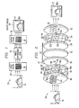
- FIGURE 1 is a block diagram illustrating a system 10 for generating an intensified image 12 of an object 14.
- An intensified image of a scene is an image in which the visible or other light or energy from the scene is intensified, increased, or otherwise enhanced.
- System 10 includes an input filter 20, an image intensifier 22, and an output filter 24.
- Input filter 20 receives photons, or energy, reflected from object 14.
- the photons include image information about object 14 that may be used to generate the intensified image 12 of object 14.
- Input filter 20 includes a number of input filter sections 30.
- Each input filter section 30 filters photons at a specific wavelength range, which may be a narrow range, single wavelength, or otherwise suitable wavelength range, and different input filter sections 30 may filter photons at different wavelength ranges.
- Each as used in this document refers to each member of a set or each member of a subset of a set.
- Wavelength ranges correspond to specific hues, which are perceived as color. For example, photons at or around a wavelength of 630 to 750 nanometers have a red hue, photons at or around a wavelength of 450 to 490 nanometers have a blue hue, and photons at or around a wavelength of 490 to 570 nanometers have a green hue. Additionally, photons at or around a wavelength of 750 nanometers to 1 millimeter have an infrared hue. Accordingly, each input filter section 30 filters photons having a specific hue, which is an attribute of the photons that describes the wavelength of photons.
- a sensor such as image intensifier 22 receives the filtered photons from input filter 20.
- Image intensifier 22 may comprise an image intensifier tube, or other suitable device capable of enhancing received energy from a scene for generation of an intensified image.
- Image intensifier 22 may multiply the photons in order to intensify a resulting image 12 generated from the photons.
- Image 12 of an object 14 in a low light area may be improved by image intensification.
- the sensor of system 10 comprises image intensifier 22, the sensor may comprise any sensor suitable for detecting an image such as a monochromatic image sensor.
- Output filter 24 receives the multiplied photons from image intensifier 22.
- Output filter 24 includes output filter sections 32. Each output filter section 32 filters photons at a specific wavelength range. Output filter sections 32 may be aligned with input filter sections 30 such that photons filtered by an input filter section 30 that filters for a wavelength range are received at an output filter section 32 that filters photons at that wavelength range.
- Input filter 20 and output filter 24 may filter photons having a number of hues. Accordingly, system 10 may provide for generating image 12 having multiple hues, which may be perceived as a multiple color image.
- An output device 34 receives the filtered photons from output filter 24 and generates image 12 from the received photons.
- Output device 34 may comprise, for example, a database, a monitor, a printer, a lens, or any other device operable to store or to display intensified image 12 of object 14.
- FIGURE 2 illustrates one embodiment of a system 20 for generating image 12 of object 14.
- System 20 includes an input lens 40, input filter 20, image intensifier 22, output filter 24, and an output lens 42.
- Input lens 40 directs photons reflected from object 14 through input filter 20 to image intensifier 22.
- Input lens 40 may comprise an objective lens having any shape and comprising any material such as glass suitable for directing photons on image intensifier 22.
- Input lens 40 includes input lens sections 44 that each direct photons through input filter sections 30 to a pixel or pixel set of image intensifier 22.
- input lens section 44a may direct photons through input filter section 30a to a pixel set of image intensifier 22.
- An input lens section 44 may have any shape suitable for directing photons to image intensifier 22.
- Input filter 20 may comprise a sensing array, where each input filter section 30 comprises a luminance-and chrominance-sensitive element. Input filter 20 may comprise input filter sections 30 that generate a multiple color image. The individual input filter sections 30 are designed to not be visible to a viewer.
- a set 72 includes input filter sections 30a-d. Input filter section 30a corresponds to a red (R) hue, input filter sections 30b and d correspond to a green (G) hue, and input filter section 30c corresponds to a blue (B) hue.
- Input filter 20 may comprise, for example, a Bayer filter having input filter sections 30 arranged in a Bayer pattern.
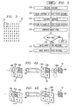
- FIGURE 3 illustrates one embodiment of input filter sections 30 arranged in a Bayer pattern.
- Input filter sections 30 comprise an arrangement of red, green, and blue sections. Rows of red and green sections alternate with rows of green and blue sections.
- Set 72 comprising a row of red and green sections and a row of green and blue sections is typically used to generate a pixel or pixel set of image 12 having multiple hues.
- set 72 of input filter sections 30 may be aligned with image intensifier 22 such that photons filtered by set 72 of input filter sections 30 are simultaneously transmitted to a tube pixel set 48 of image intensifier.
- set 70 of input filter sections 30 may be moved such that each input filter section 30 directs photons onto tube pixel set 48 at different times. For example, input filter section 30a corresponding to red directs photons onto tube pixel set 48, then input filter section 30b corresponding to green directs photons onto tube pixel set 48, then input filter section 30c corresponding to blue directs photons onto tube pixel set 48, then input filter section 30d corresponding to green directs photons onto tube pixel set 48.
- input filter sections 30a-d are sufficiently spaced and move sufficiently fast, the human eye cannot detect the movement and the resulting image 12 may be perceived as having multiple colors.
- input filter sections may move approximately 60 frames per second, where one frame comprises directing photons from each input filter section 30a-d of set 72 on tube pixel set 48.
- input filter 20 may also include optional displacement devices 46 that move input filter sections 30 to direct light filtered by input filter sections 30 to tube pixel set 48 in order to change the wavelength of light directed to tube pixel set 48.
- Displacement device 46 may include a displacement device 46 that moves input filter 20 in an x-direction and a displacement device 46 that moves input filter 20 in a y-direction. Displacement devices 46 may work together to move input filter 20 in a smooth motion. Displacement devices 46 may comprise, for example, Piezo electric transducers.
- Image intensifier 22 includes a photocathode 50, a microchannel plate 52, and a phosphor screen 54.
- Photocathode 50 converts photons received from input filter 20 into electrons, and may comprise, for example, gallium arsenide.
- a layer 51 may be disposed outwardly from photocathode 50.
- Layer 51 may comprise a translucent material such as frosted glass, which may protect photocathode 50 from contamination.
- Microchannel plate 52 multiplies electrons received from photocathode 50.
- Microchannel plate 52 may comprise a transparent material such as glass with any number of microscopic microchannels that function as electron multipliers that multiply electrons using a cascaded secondary emission process.
- Phosphor screen 54 converts the multiplied electrons received from microchannel plate 52 to photons.
- Phosphor screen 54 may comprise a screen having a coating of a white phosphor such as P 45 that transmits a photon in response to receiving an electron.
- Image intensifier 22 may operate under a vacuum of, for example, 10 -9 torr, or any other vacuum suitable for the operation of image intensifier 22
- Output filter 24 may be substantially similar to input filter 22.
- Output filter 24 may include output filter sections 32 that filter for photons at specific wavelength ranges.
- set 72 comprises output filter sections 32a-d.
- Output filter section 32a filters photons having a red hue
- output filter sections 32b and 32d filter photons having a green hue
- output filter section 32c filters photons having a blue hue.
- Output filter sections 32 may be aligned with input filter sections 30 such that photons that are filtered by an input filter section 30 at a specific wavelength range are received at an output filter section 32 that filters at that specific wavelength range.
- output filter section 32a that filters photons having a red hue may be aligned to receive photons filtered by input filter section 30a that filters photons also having a red hue.
- Output filter 24 may also include displacement devices 56 that may be used to align output filter section 32 with the corresponding input filter sections 30. Displacement devices 56 may be substantially similar to displacement devices 46.
- Output device 34 may comprise output lens 42, which magnifies and focuses photons received from output filter 24 in order to generate image 12.
- Output lens 42 may comprise output lens sections 58, and may be substantially similar to input lens 40.
- Output filter 24 and input filter 20 may have differences.
- output filter 24 may have features to correct for the spectral characteristics of phosphor screen 54.
- Output filter 24 may include tint control features that are absent in input filter 20.
- FIGURES 4A and 4B illustrate movement of input filter sections 30 and output filter sections 32 to generate an image pixel set 60 having multiple hues.
- FIGURE 4A illustrates input filter sections 30 and output filter sections 32 at a first position that yields an image pixel set 60 having a green hue.
- Input lens section 44b directs photons through input filter section 30b that filters photons having a green hue onto tube pixel set 48.
- Tube pixel set 48 receives the green filtered photons, and image intensifier 22 multiplies the photons.
- Output filter section 32b that filters for photons having a green hue receives the multiplied photons.
- Output lens section 58b directs the photons from tube pixel set 48 through output filter section 32b to generate image pixel set 60 having a green hue.
- FIGURE 4B illustrates input filter sections 30 and output filter sections 32 at a second position to generate image pixel set 60 having a red hue.
- Input lens section 44a directs photons through input filter section 30a that filters photons having a red hue onto tube pixel set 48.
- Tube pixel set 48 receives the red filtered photons, and image intensifier 22 multiplies the photons.
- Output filter section 32a that filters for photons having a red hue receives the multiplied photons.
- Output lens section 58a directs photons from tube pixel set 48 through output filter section 32a to generate image pixel set 60 having a red hue.
- input filter sections 30 and output filter sections 32 move with respect to tube pixel set 48 and image pixel set 60 in order to first direct green-filtered photons on image pixel set 60 and then direct red-filtered photons on image pixel set 60.
- Any suitable change in relative position between input filter sections 30, pixel set 48, output filter sections 32, and image pixel set 60 may be used in order to change the hue of image pixel set 60.
- tube pixel set 48 and image pixel set 60 may move with respect to input filter sections 30 and output filter sections 32 in order to change the hue of image pixel set 60.
- Figure 5 is a flowchart illustrating a method for generating an image having multiple hues.
- the method begins at step 100, where system 20 receives photons reflected from or generated by object 14.
- Input filter sections 30 and output filter sections 32 are at the first position as illustrated in Figure 4A .
- Input lens section 44b directs photons through input filter section 30b to tube pixel set 48.
- photons having a green hue are filtered at input filter section 30b. Filtered photons are multiplied at step 104.
- the multiplied photons are filtered at output filter section 32b that corresponds to green.
- Image pixel set 60 having a green hue is generated at step 108.
- the method determines whether there is a next hue. If there is a next hue, the method proceeds to step 112 to move input filter sections 30 to a second position, as illustrated in Figure 4B . Output filter sections 32 are moved to be aligned with input filter sections 30 at step 114. The method then returns to step 102 to filter photons having a red hue at input filter section 30a. The filtered photons are multiplied at step 104, and the multiplied photons are filtered at output filter section 32a that correspond to red at step 106. Image pixel set 60 having red hue is generated at step 108. If there is no next hue at step 110, the method terminates.
- FIG. 6A illustrates input obscurant 62 and output obscurant 64 at a first position that yields an image pixel set 60 having a green hue.
- Input obscurant 62 directs photons towards input filter section 30b that filters photons having a green hue.
- Input obscurant 62 and output obscurant 64 may direct photons by allowing some photons to pass through an opening and blocking other photons.
- Tube pixel set 48 receives the green filtered photons, and image intensifier 22 multiplies the photons.
- Output obscurant 64 directs the photons from tube pixel set 48 through output filter section 32b that filters for photons having a green hue. The filtered photons generate image pixel set 60 having a green hue.
- FIGURE 6B illustrates input obscurant 62 and output obscurant 64 at a second position to generate image pixel set 60 having a blue hue.
- Input obscurant 62 directs photons through input filter section 30c that filters for photons having a blue hue.
- Tube pixel set 48 receives the blue filtered photons, and image intensifier 22 multiplies the photons.
- Output obscurant 64 directs photons towards output filter section 32c that filters for photons having a blue hue. The filtered photons generate image pixel 60 having a blue hue.
- input obscurant 62 and output obscurant 64 move with respect to tube pixel set 48 in order to first direct green-filtered photons on image pixel set 60 and then direct blue-filtered photons on image pixel set 60.
- Any suitable change in the relative positions between input obscurant 62, input filter section 30, tube pixel set 48, output obscurant 64, and output filter sections 32 may be used to change the hue of image pixel set 60.
- input filter sections 30 and output filter sections 32 may move with respect to tube pixel set 48 and image pixel set 60 in order to change the hue of image pixel set 60.
- Embodiments of the invention may provide technical advantages.
- a technical advantage of one embodiment is that image 12 having at least two colors may be generated.
- Input filter 20 and output filter 24 have different filter sections 30 and 32 that respond to different wavelengths.
- Image intensifier 22 multiplies photons received from input filter sections 30, and transmits the multiplied photons to output filter sections 32. The photons received at the output filter sections 32 are used to generate image 12 having at least two colors.
- displacement devices 46 and 56 may be used to move input filter 20 and output filter 24 such that photons filtered by input filter section 30 that filters for a wavelength range are received at output filter section 32 that also filters photons at that wavelength range. Displacement devices 46 and 56 may move input filter sections 30 and output filter sections 32 with sufficient speed such that the human eye cannot detect the movement.
- input lens 40 may include input lens sections 44 that direct photons through input filter sections 30 onto pixel set 48 of image intensifier 22.
- an input lens section 44 may direct photons through an input filter section 30 corresponding to a red color to pixel set 48
- another input lens section 44 may direct photons through an input filter section 30 corresponding to a blue color to pixel set 48.
- Layer 51 between input filter 20 and photocathode 50 of image intensifier 22 may be used to protect photocathode 50 from contamination.
Landscapes
- Color Television Image Signal Generators (AREA)
- Image-Pickup Tubes, Image-Amplification Tubes, And Storage Tubes (AREA)
- Apparatus For Radiation Diagnosis (AREA)
Claims (16)
- System (10) zur Erzeugung eines Bildes (12) mit einer Vielzahl von Farbtönen, umfassend:einen Eingangsfilter (20), umfassend:einen ersten Eingangsfilterabschnitt (30a-d), betreibbar zum Filtern einer Vielzahl erster Photonen in einem ersten Wellenlängenbereich; undeinen zweiten Eingangsfilterabschnitt (30a-d), betreibbar zum Filtern einer Vielzahl zweiter Photonen in einem zweiten Wellenlängenbereich;einen Bildverstärker, umfassend ein Röhrenpixelset (48) und betreibbar zum Vervielfachen der ersten Photonen und der zweiten Photonen, ausgerichtet auf das Röhrenpixelset;einen Ausgangsfilter (24), der die ersten vervielfachten Photonen und die zweiten vervielfachten Photonen von dem Bildverstärker empfängt, wobei das Ausgangsfilter umfasst:einen ersten Ausgangsfilterabschnitt (32a-d), betreibbar zum Filtern der ersten vervielfachten Photonen; und einen zweiten Ausgangsfilterabschnitt (32a-d), betreibbar zum Filtern der zweiten vervielfachten Photonen; undeine Ausgangseinheit (42), betreibbar zum Empfangen der ersten vervielfachten Photonen und der zweiten vervielfachten Photonen vom Ausgangsfilter und zum Erstellen eines Bildes (12) aus den ersten vervielfachten Photonen und der zweiten vervielfachten Photonen;dadurch gekennzeichnet, dass das System ferner umfasst:einen ersten Eingangslinsenabschnitt (44a) einer Eingangslinse (40), betreibbar zum Leiten der ersten Photonen auf das Röhrenpixelset; undeinen zweiten Eingangslinsenabschnitt (44b) einer Eingangslinse (40), betreibbar zum Leiten der zweiten Photonen auf das Röhrenpixelset
- System nach Anspruch 1, zusätzlich einen Sensor umfassend, wobei der Sensor den Bildverstärker (22) umfasst.
- System nach Anspruch 1, wobei:der erste Eingangsfilterabschnitt (30a-d) betreibbar zum Bewegen und zum Leiten der ersten Photonen auf das Röhrenpixelset (48) ist; der erste Ausgangsfilterabschnitt (32a-d) betreibbar zum Bewegen und zum Empfangen der auf das Röhrenpixelset (48) ausgerichteten ersten Photonen ist; der zweite Eingangsfilterabschnitt (30a-d) betreibbar zum Bewegen und zum Leiten der zweiten Photonen auf das Röhrenpixelset (48) ist; der zweite Ausgangsfilterabschnitt (32a-d) betreibbar zum Bewegen und zum Empfangen der auf das Röhrenpixelset (48) ausgerichteten zweiten Photonen ist.
- System nach Anspruch 1, ferner umfassend
eine Eingangsabschirmeinheit (62), die dazu dient, die ersten Photonen auf den ersten Eingangsfilterabschnitt (30a-d) zu leiten; und die zweiten Photonen auf den zweiten Eingangsfilterabschnitt (30a-d) zu leiten; eine Ausgangsabschirmeinheit (64), die dazu dient, die ersten vervielfachten Photonen auf den ersten Ausgangsfilterabschnitt (32a-d) zu leiten; und die zweiten vervielfachten Photonen auf den zweiten Ausgangsfilterabschnitt (32a-d) zu leiten. - System nach Anspruch 1, wobei das Eingangsfilter (20) eine Vielzahl von lichtempfindlichen Elementen (30) umfasst.
- System nach Anspruch 1, wobei das Eingangsfilter (20) die Eingangsfilterabschnitte (30) umfasst, welche entsprechend einer Bayer-Matrix konfiguriert sind.
- Verfahren zur Erzeugung eines Bildes (12) mit einer Vielzahl von Farbtönen, umfassend:Filtern einer Vielzahl von ersten Photonen eines ersten Wellenlängenbereiches mit einem ersten Eingangsfilterabschnitt (30a-d) eines Eingangsfilters (20);Filtern einer Vielzahl von zweiten Photonen eines zweiten Wellenlängenbereiches mit einem zweiten Eingangsfilterabschnitt (30a-d) des Eingangsfilters (20);Leiten der ersten Photonen auf ein Röhrenpixelset (48) eines Sensors mittels eines ersten Eingangslinsenabschnitts (44a) der Eingangslinse (40);Leiten der zweiten Photonen auf das Röhrenpixelset (48) mittels eines zweiten Eingangslinsenabschnitts (44b) einer Eingangslinse (40);Vervielfachen der ersten Photonen und der zweiten Photonen beim Sensor;Filtern erster vervielfachter Photonen mittels eines ersten Ausgangsfilterabschnitts (32a-d) eines Ausgangsfilters (24);Filtern zweiter vervielfachter Photonen mittels eines zweiten Ausgangsfilterabschnitts (32a-d) des Ausgangsfilters (24); undErzeugung eines Bildes (12) aus den ersten vervielfachten Photonen und den vervielfachten zweiten Photonen.
- Verfahren nach Anspruch 7, wobei der Sensor einen Bildverstärker (22) umfasst.
- Verfahren nach Anspruch 7, ferner umfassend:Bewegen des ersten Eingangsfilterabschnitts (30a-d), um die ersten Photonen auf das Röhrenpixelset (48) zu leiten;Bewegen des ersten Ausgangsfilterabschnitts (32a-d), um die ersten vervielfachten Photonen zu empfangen;Bewegen des zweiten Eingangsfilterabschnitts (30a-d), um die zweiten Photonen auf das Röhrenpixelset (48) zu leiten; undBewegen des zweiten Ausgangsfilterabschnitts (32a-d), um die zweiten vervielfachten Photonen zu empfangen.
- Verfahren nach Anspruch 7, ferner umfassend:Bewegen der Eingangsabschirmeinheit (62), um die ersten Photonen auf den ersten Eingangsfilterabschnitt (30a-d) zu leiten;Bewegen der Ausgangsabschirmeinheit (64), um die ersten vervielfachten Photonen auf den ersten Ausgangsfilterabschnitt (32a-d) zu leiten;Bewegen der Eingangsabschirmeinheit (62), um die zweiten Photonen auf den zweiten Eingangsfilterabschnitt (30a-d) zu leiten; undBewegen der Ausgangsabschirmeinheit (64), um die zweiten vervielfachten Photonen auf den zweiten Ausgangsfilterabschnitt (32a-d) zu leiten.
- Verfahren nach Anspruch 7, wobei das Eingangsfilter (20) die Eingangsfilterabschnitte(30a-d) umfasst, welche entsprechend einer Bayer-Matrix konfiguriert sind.
- Verfahren zur Erzeugung eines Bildes (12) nach Anspruch 7 mit einer Vielzahl von Farbtönen, umfassend:Bewegen eines ersten Eingangsfilterabschnitts (30a-d) eines Eingangsfilters (20), um eine Vielzahl erster Photonen in einem ersten Wellenlängenbereich auf ein Röhrenpixelset (48) eines Sensors zu leiten;Filtern der ersten Photonen mittels des ersten Eingangsfilterabschnitts (30a-d);Vervielfachen der ersten Photonen beim Sensor;Bewegen eines ersten Ausgangsfilterabschnitts (32a-d) eines Ausgangsfilters (24), um die vervielfachten ersten Photonen zu empfangen;Filtern der ersten vervielfachten Photonen mittels des ersten Ausgangsfilterabschnitts (32a-d);Bewegen eines zweiten Eingangsfilterabschnitts (30a-d) des Eingangsfilters (20), um eine Vielzahl zweiter Photonen in einem zweiten Wellenlängenbereich auf ein Röhrenpixelset (48) zu leiten;Filtern der zweiten Photonen mittels des zweiten Eingangsfilterabschnitts (32a-d);Vervielfachen der zweiten Photonen beim Sensor;Bewegen eines zweiten Ausgangsfilterabschnitts (32a-d) des Ausgangsfilters, um die zweiten vervielfachten Photonen zu empfangen;Filtern der zweiten vervielfachten Photonen mittels des zweiten Ausgangsfilterabschnitts (32a-d); undErzeugung eines Bildes (12) aus den ersten vervielfachten Photonen und den zweiten vervielfachten Photonen.
- Verfahren nach Anspruch 12, wobei der Sensor einen Bildverstärker (22) umfasst.
- Verfahren nach Anspruch 12, zusätzlich umfassend:Leiten der ersten Photonen auf das Röhrenpixelset (48) mittels eines ersten Eingangslinsenabschnitts (44a) einer Eingangslinse (40); undLeiten der zweiten Photonen auf das Röhrenpixelset (48) mittels eines zweiten Eingangslinsenabschnitts (44b) der Eingangslinse (40).
- Verfahren nach Anspruch 14, wobei das Eingangsfilter (20) die Eingangsfilterabschnitte (30) umfasst, welche entsprechend einer Bayer-Matrix konfiguriert sind.
- Verfahren zur Erzeugung eines Bildes (12) nach Anspruch 7 mit mehreren Farbtönen, umfassend:Bewegen eines ersten Eingangsfilterabschnitts (30a-d) eines Eingangsfilters (20), um eine Vielzahl von ersten Photonen in einem ersten Wellenlängenbereich auf ein Röhrenpixelset (48) eines Bildverstärkers (22) zu leiten, wobei das Eingangsfilter eine Vielzahl von Eingangsfilterabschnitten (30) umfasst, konfiguriert in einer Bayer-Matrix, wobei der erste Wellenlängenbereich einem ersten Farbton entspricht;Leiten der ersten Photonen auf den ersten Eingangsfilterabschnitt (30a-d) mittels eines ersten Eingangslinsenabschnitts (44a) einer Eingangslinse (40);Filtern der ersten Photonen mittels des ersten Eingangsfilterabschnitts (30a-d);Vervielfachen der ersten Photonen beim Bildverstärker (22);Bewegen eines ersten Ausgangsfilterabschnitts (32a-d) eines Ausgangsfilters (24), um erste vervielfachte Photonen zu empfangen;Filtern der ersten vervielfachten Photonen mittels des ersten Ausgangsfilterabschnitts (32a-d);Bewegen eines zweiten Eingangsfilterabschnitts (30a-d) des Eingangsfilters, um eine Vielzahl zweiter Photonen in einem zweiten Wellenlängenbereich auf ein Röhrenpixelset (48) zu leiten, wobei der zweite Wellenlängenbereich einem zweiten Farbton entspricht;Leiten der zweiten Photonen auf den zweiten Eingangsfilterabschnitt (30a-d) mittels eines zweiten Eingangslinsenabschnitts (44b) der Eingangslinse (40);Filtern der zweiten Photonen mittels des zweiten Eingangsfilterabschnitts (30a-d); Vervielfachen der zweiten Photonen beim Bildverstärker (22);Bewegen eines zweiten Ausgangsfilterabschnitts (32a-d) des Ausgangsfilters, um zweite vervielfachte Photonen zu empfangen;Filtern der zweiten vervielfachten Photonen mittels des zweiten Ausgangsfilterabschnitts (32a-d); undErzeugung eines Bildes (12) aus den ersten vervielfachten Photonen und den zweiten vervielfachten Photonen.
Applications Claiming Priority (3)
| Application Number | Priority Date | Filing Date | Title |
|---|---|---|---|
| US224924 | 2002-08-20 | ||
| US10/224,924 US6861638B2 (en) | 2002-08-20 | 2002-08-20 | Method and system for generating an image having multiple hues |
| PCT/US2003/025316 WO2004019367A1 (en) | 2002-08-20 | 2003-08-12 | Method and system for generating an image having multiple hues using an image intensifier |
Publications (2)
| Publication Number | Publication Date |
|---|---|
| EP1530797A1 EP1530797A1 (de) | 2005-05-18 |
| EP1530797B1 true EP1530797B1 (de) | 2011-10-05 |
Family
ID=31886914
Family Applications (1)
| Application Number | Title | Priority Date | Filing Date |
|---|---|---|---|
| EP03793045A Expired - Lifetime EP1530797B1 (de) | 2002-08-20 | 2003-08-12 | Verfahren und vorrichtung zur erzeugung eines bildes mit verschiedenen farbtoenen mit einem bildverstärker |
Country Status (6)
| Country | Link |
|---|---|
| US (2) | US6861638B2 (de) |
| EP (1) | EP1530797B1 (de) |
| AT (1) | ATE527677T1 (de) |
| AU (1) | AU2003262632B2 (de) |
| CA (1) | CA2492525C (de) |
| WO (1) | WO2004019367A1 (de) |
Families Citing this family (14)
| Publication number | Priority date | Publication date | Assignee | Title |
|---|---|---|---|---|
| US6861638B2 (en) * | 2002-08-20 | 2005-03-01 | Northrop Grumman Corporation | Method and system for generating an image having multiple hues |
| RU2308116C1 (ru) * | 2005-12-14 | 2007-10-10 | Открытое акционерное общество Центральный научно-исследовательский институт "ЦИКЛОН" | Электронно-оптический преобразователь и способ получения видеоизображения |
| SG174346A1 (en) | 2009-03-19 | 2011-11-28 | Millipore Corp | Removal of microorganisms from fluid samples using nanofiber filtration media |
| US8684560B2 (en) * | 2009-11-18 | 2014-04-01 | Stanley Electric Co., Ltd. | Semiconductor light source apparatus and lighting unit |
| RU2525827C2 (ru) * | 2012-06-04 | 2014-08-20 | Открытое акционерное общество центральный научно-исследовательский институт "Ц И К Л О Н" | Электронно-оптический преобразователь и способ получения видеоизображения |
| JP2014137973A (ja) | 2013-01-18 | 2014-07-28 | Stanley Electric Co Ltd | 光源装置 |
| US9503623B2 (en) | 2014-06-03 | 2016-11-22 | Applied Minds, Llc | Color night vision cameras, systems, and methods thereof |
| FR3026223B1 (fr) * | 2014-09-22 | 2016-12-23 | Photonis France | Dispositif d'acquisition d'images bimode a photocathode. |
| US10805600B2 (en) | 2016-07-29 | 2020-10-13 | Applied Minds, Llc | Methods and associated devices and systems for enhanced 2D and 3D vision |
| US20190098264A1 (en) * | 2017-03-21 | 2019-03-28 | Irvine Sensors Corporation | Image Intensified Color Camera |
| RU2734075C1 (ru) * | 2020-05-21 | 2020-10-12 | Общество с ограниченной ответственностью «КАТОД» | Способ и устройство для изготовления электродного узла для фотоэлектронного прибора |
| US11871115B2 (en) | 2021-10-12 | 2024-01-09 | L3Harris Technologies, Inc. | Color night vision through the spatial filtering of TOLED technology |
| FR3157657A1 (fr) | 2023-12-22 | 2025-06-27 | Photonis France | Tube intensificateur d’images couleur et dispositif de vision nocturne en couleur associe |
| FR3158585A1 (fr) | 2024-01-18 | 2025-07-25 | Photonis France | Dispositif d’acquisition d’images couleurs et systeme de vision nocturne en couleurs associe |
Family Cites Families (10)
| Publication number | Priority date | Publication date | Assignee | Title |
|---|---|---|---|---|
| US2713083A (en) * | 1951-12-22 | 1955-07-12 | Columbia Broadcasting Syst Inc | Color switching system |
| NL279475A (de) * | 1961-06-09 | |||
| US4724354A (en) | 1986-05-05 | 1988-02-09 | Eol3 Company, Inc. | Image intensifier for producing a color image having a color separation filter sequentially passing visible blue light and its second order wavelengths, visible green light and its second order wavelengths, and visible red light |
| US5162647A (en) * | 1991-02-28 | 1992-11-10 | Itt Corporation | Color image intensifier device utilizing color input and output filters being offset by a slight phase lag |
| JP2788681B2 (ja) | 1991-06-24 | 1998-08-20 | 浜松ホトニクス株式会社 | 単管カラー暗視装置 |
| US5233183A (en) | 1991-07-26 | 1993-08-03 | Itt Corporation | Color image intensifier device and method for producing same |
| US5241170A (en) * | 1992-02-19 | 1993-08-31 | Itt Corporation | Fiber optic imaging device and methods |
| IL114181A (en) | 1995-06-15 | 1999-07-14 | Orlil Ltd | Color image intensifier device and a method for producing the same |
| US5756989A (en) * | 1996-11-22 | 1998-05-26 | Mcdonnell Douglas Corporation | Color night vision goggles capable of providing anti-jamming protection against pulsed and continuous wave jamming lasers |
| US6861638B2 (en) * | 2002-08-20 | 2005-03-01 | Northrop Grumman Corporation | Method and system for generating an image having multiple hues |
-
2002
- 2002-08-20 US US10/224,924 patent/US6861638B2/en not_active Expired - Lifetime
-
2003
- 2003-08-12 AU AU2003262632A patent/AU2003262632B2/en not_active Ceased
- 2003-08-12 AT AT03793045T patent/ATE527677T1/de not_active IP Right Cessation
- 2003-08-12 CA CA2492525A patent/CA2492525C/en not_active Expired - Fee Related
- 2003-08-12 WO PCT/US2003/025316 patent/WO2004019367A1/en not_active Ceased
- 2003-08-12 EP EP03793045A patent/EP1530797B1/de not_active Expired - Lifetime
-
2005
- 2005-02-28 US US11/068,257 patent/US7098436B2/en not_active Expired - Fee Related
Also Published As
| Publication number | Publication date |
|---|---|
| AU2003262632A1 (en) | 2004-03-11 |
| HK1073174A1 (en) | 2005-09-23 |
| CA2492525A1 (en) | 2004-03-04 |
| US7098436B2 (en) | 2006-08-29 |
| CA2492525C (en) | 2011-10-25 |
| US20040036013A1 (en) | 2004-02-26 |
| US20050145778A1 (en) | 2005-07-07 |
| EP1530797A1 (de) | 2005-05-18 |
| WO2004019367A1 (en) | 2004-03-04 |
| AU2003262632B2 (en) | 2007-10-04 |
| ATE527677T1 (de) | 2011-10-15 |
| US6861638B2 (en) | 2005-03-01 |
Similar Documents
| Publication | Publication Date | Title |
|---|---|---|
| EP1530797B1 (de) | Verfahren und vorrichtung zur erzeugung eines bildes mit verschiedenen farbtoenen mit einem bildverstärker | |
| US6570147B2 (en) | Color night vision apparatus | |
| EP0325361B1 (de) | Farbprojektionssystem | |
| US11120534B2 (en) | Color night vision goggle | |
| EP0226423B1 (de) | Farbbildröhre | |
| US5162647A (en) | Color image intensifier device utilizing color input and output filters being offset by a slight phase lag | |
| EP1836522B1 (de) | Synthetisches farb-nachtsichtsystem | |
| JPH09171787A (ja) | カラー画像増倍器及びカラー画像の処理方法 | |
| US20210381824A1 (en) | Lidar system and motor vehicle | |
| EP4167014B1 (de) | Farbnachtsicht durch räumliche filterung von toled-technologie | |
| US8363134B2 (en) | Color imaging device, imaging apparatus using the same, and filter | |
| US5097324A (en) | Beam-index color display unit | |
| HK1073174B (en) | Method and system for generating an image having multiple hues using an image intensifier | |
| JP2024087739A (ja) | 暗視装置 | |
| Lemonier et al. | Low light level TV imaging by intensified CCDs | |
| JP2004080605A (ja) | 撮像装置 | |
| KR102271555B1 (ko) | 컬러 영상 획득장치 | |
| US7235768B1 (en) | Solid state vision enhancement device | |
| TW202539256A (zh) | 彩色影像擷取裝置及相關彩色夜視系統 | |
| Sturz | Evolving image intensifier technology | |
| RU2216068C2 (ru) | Устройство для получения цветного изображения в условиях низкой освещенности | |
| Gertsenshteyn et al. | Color direct vision image intensifier | |
| RU13737U1 (ru) | Низкоуровневая цветная телевизионная система | |
| JP3366374B2 (ja) | 画質計測装置 | |
| JP2006119551A (ja) | 立体光学像表示装置および立体光学像表示窓装置 |
Legal Events
| Date | Code | Title | Description |
|---|---|---|---|
| PUAI | Public reference made under article 153(3) epc to a published international application that has entered the european phase |
Free format text: ORIGINAL CODE: 0009012 |
|
| 17P | Request for examination filed |
Effective date: 20050311 |
|
| AK | Designated contracting states |
Kind code of ref document: A1 Designated state(s): AT BE BG CH CY CZ DE DK EE ES FI FR GB GR HU IE IT LI LU MC NL PT RO SE SI SK TR |
|
| AX | Request for extension of the european patent |
Extension state: AL LT LV MK |
|
| REG | Reference to a national code |
Ref country code: HK Ref legal event code: DE Ref document number: 1073174 Country of ref document: HK |
|
| DAX | Request for extension of the european patent (deleted) | ||
| 17Q | First examination report despatched |
Effective date: 20070711 |
|
| GRAP | Despatch of communication of intention to grant a patent |
Free format text: ORIGINAL CODE: EPIDOSNIGR1 |
|
| GRAS | Grant fee paid |
Free format text: ORIGINAL CODE: EPIDOSNIGR3 |
|
| GRAA | (expected) grant |
Free format text: ORIGINAL CODE: 0009210 |
|
| AK | Designated contracting states |
Kind code of ref document: B1 Designated state(s): AT BE BG CH CY CZ DE DK EE ES FI FR GB GR HU IE IT LI LU MC NL PT RO SE SI SK TR |
|
| REG | Reference to a national code |
Ref country code: GB Ref legal event code: FG4D |
|
| REG | Reference to a national code |
Ref country code: CH Ref legal event code: EP |
|
| REG | Reference to a national code |
Ref country code: IE Ref legal event code: FG4D |
|
| REG | Reference to a national code |
Ref country code: DE Ref legal event code: R096 Ref document number: 60338686 Country of ref document: DE Effective date: 20111208 |
|
| REG | Reference to a national code |
Ref country code: SE Ref legal event code: TRGR |
|
| PG25 | Lapsed in a contracting state [announced via postgrant information from national office to epo] |
Ref country code: SI Free format text: LAPSE BECAUSE OF FAILURE TO SUBMIT A TRANSLATION OF THE DESCRIPTION OR TO PAY THE FEE WITHIN THE PRESCRIBED TIME-LIMIT Effective date: 20111005 |
|
| REG | Reference to a national code |
Ref country code: AT Ref legal event code: MK05 Ref document number: 527677 Country of ref document: AT Kind code of ref document: T Effective date: 20111005 |
|
| REG | Reference to a national code |
Ref country code: HK Ref legal event code: GR Ref document number: 1073174 Country of ref document: HK |
|
| PG25 | Lapsed in a contracting state [announced via postgrant information from national office to epo] |
Ref country code: BE Free format text: LAPSE BECAUSE OF FAILURE TO SUBMIT A TRANSLATION OF THE DESCRIPTION OR TO PAY THE FEE WITHIN THE PRESCRIBED TIME-LIMIT Effective date: 20111005 |
|
| PG25 | Lapsed in a contracting state [announced via postgrant information from national office to epo] |
Ref country code: PT Free format text: LAPSE BECAUSE OF FAILURE TO SUBMIT A TRANSLATION OF THE DESCRIPTION OR TO PAY THE FEE WITHIN THE PRESCRIBED TIME-LIMIT Effective date: 20120206 Ref country code: GR Free format text: LAPSE BECAUSE OF FAILURE TO SUBMIT A TRANSLATION OF THE DESCRIPTION OR TO PAY THE FEE WITHIN THE PRESCRIBED TIME-LIMIT Effective date: 20120106 |
|
| PG25 | Lapsed in a contracting state [announced via postgrant information from national office to epo] |
Ref country code: CY Free format text: LAPSE BECAUSE OF FAILURE TO SUBMIT A TRANSLATION OF THE DESCRIPTION OR TO PAY THE FEE WITHIN THE PRESCRIBED TIME-LIMIT Effective date: 20111005 |
|
| PG25 | Lapsed in a contracting state [announced via postgrant information from national office to epo] |
Ref country code: CZ Free format text: LAPSE BECAUSE OF FAILURE TO SUBMIT A TRANSLATION OF THE DESCRIPTION OR TO PAY THE FEE WITHIN THE PRESCRIBED TIME-LIMIT Effective date: 20111005 Ref country code: DK Free format text: LAPSE BECAUSE OF FAILURE TO SUBMIT A TRANSLATION OF THE DESCRIPTION OR TO PAY THE FEE WITHIN THE PRESCRIBED TIME-LIMIT Effective date: 20111005 Ref country code: SK Free format text: LAPSE BECAUSE OF FAILURE TO SUBMIT A TRANSLATION OF THE DESCRIPTION OR TO PAY THE FEE WITHIN THE PRESCRIBED TIME-LIMIT Effective date: 20111005 Ref country code: EE Free format text: LAPSE BECAUSE OF FAILURE TO SUBMIT A TRANSLATION OF THE DESCRIPTION OR TO PAY THE FEE WITHIN THE PRESCRIBED TIME-LIMIT Effective date: 20111005 Ref country code: BG Free format text: LAPSE BECAUSE OF FAILURE TO SUBMIT A TRANSLATION OF THE DESCRIPTION OR TO PAY THE FEE WITHIN THE PRESCRIBED TIME-LIMIT Effective date: 20120105 |
|
| PLBE | No opposition filed within time limit |
Free format text: ORIGINAL CODE: 0009261 |
|
| STAA | Information on the status of an ep patent application or granted ep patent |
Free format text: STATUS: NO OPPOSITION FILED WITHIN TIME LIMIT |
|
| PG25 | Lapsed in a contracting state [announced via postgrant information from national office to epo] |
Ref country code: RO Free format text: LAPSE BECAUSE OF FAILURE TO SUBMIT A TRANSLATION OF THE DESCRIPTION OR TO PAY THE FEE WITHIN THE PRESCRIBED TIME-LIMIT Effective date: 20111005 Ref country code: IT Free format text: LAPSE BECAUSE OF FAILURE TO SUBMIT A TRANSLATION OF THE DESCRIPTION OR TO PAY THE FEE WITHIN THE PRESCRIBED TIME-LIMIT Effective date: 20111005 |
|
| 26N | No opposition filed |
Effective date: 20120706 |
|
| PGFP | Annual fee paid to national office [announced via postgrant information from national office to epo] |
Ref country code: GB Payment date: 20120821 Year of fee payment: 10 Ref country code: SE Payment date: 20120821 Year of fee payment: 10 |
|
| REG | Reference to a national code |
Ref country code: DE Ref legal event code: R097 Ref document number: 60338686 Country of ref document: DE Effective date: 20120706 |
|
| PGFP | Annual fee paid to national office [announced via postgrant information from national office to epo] |
Ref country code: TR Payment date: 20120724 Year of fee payment: 10 |
|
| PGFP | Annual fee paid to national office [announced via postgrant information from national office to epo] |
Ref country code: FR Payment date: 20120906 Year of fee payment: 10 Ref country code: DE Payment date: 20120822 Year of fee payment: 10 |
|
| PG25 | Lapsed in a contracting state [announced via postgrant information from national office to epo] |
Ref country code: AT Free format text: LAPSE BECAUSE OF FAILURE TO SUBMIT A TRANSLATION OF THE DESCRIPTION OR TO PAY THE FEE WITHIN THE PRESCRIBED TIME-LIMIT Effective date: 20111005 |
|
| PGFP | Annual fee paid to national office [announced via postgrant information from national office to epo] |
Ref country code: NL Payment date: 20120821 Year of fee payment: 10 |
|
| PG25 | Lapsed in a contracting state [announced via postgrant information from national office to epo] |
Ref country code: MC Free format text: LAPSE BECAUSE OF NON-PAYMENT OF DUE FEES Effective date: 20120831 |
|
| PG25 | Lapsed in a contracting state [announced via postgrant information from national office to epo] |
Ref country code: ES Free format text: LAPSE BECAUSE OF FAILURE TO SUBMIT A TRANSLATION OF THE DESCRIPTION OR TO PAY THE FEE WITHIN THE PRESCRIBED TIME-LIMIT Effective date: 20120116 |
|
| REG | Reference to a national code |
Ref country code: IE Ref legal event code: MM4A |
|
| PG25 | Lapsed in a contracting state [announced via postgrant information from national office to epo] |
Ref country code: FI Free format text: LAPSE BECAUSE OF FAILURE TO SUBMIT A TRANSLATION OF THE DESCRIPTION OR TO PAY THE FEE WITHIN THE PRESCRIBED TIME-LIMIT Effective date: 20111005 |
|
| PG25 | Lapsed in a contracting state [announced via postgrant information from national office to epo] |
Ref country code: IE Free format text: LAPSE BECAUSE OF NON-PAYMENT OF DUE FEES Effective date: 20120812 |
|
| REG | Reference to a national code |
Ref country code: NL Ref legal event code: V1 Effective date: 20140301 |
|
| REG | Reference to a national code |
Ref country code: CH Ref legal event code: PL |
|
| REG | Reference to a national code |
Ref country code: SE Ref legal event code: EUG |
|
| GBPC | Gb: european patent ceased through non-payment of renewal fee |
Effective date: 20130812 |
|
| PG25 | Lapsed in a contracting state [announced via postgrant information from national office to epo] |
Ref country code: DE Free format text: LAPSE BECAUSE OF NON-PAYMENT OF DUE FEES Effective date: 20140301 Ref country code: LI Free format text: LAPSE BECAUSE OF NON-PAYMENT OF DUE FEES Effective date: 20130831 Ref country code: SE Free format text: LAPSE BECAUSE OF NON-PAYMENT OF DUE FEES Effective date: 20130813 Ref country code: NL Free format text: LAPSE BECAUSE OF NON-PAYMENT OF DUE FEES Effective date: 20140301 Ref country code: CH Free format text: LAPSE BECAUSE OF NON-PAYMENT OF DUE FEES Effective date: 20130831 |
|
| REG | Reference to a national code |
Ref country code: DE Ref legal event code: R119 Ref document number: 60338686 Country of ref document: DE Effective date: 20140301 |
|
| REG | Reference to a national code |
Ref country code: FR Ref legal event code: ST Effective date: 20140430 |
|
| PG25 | Lapsed in a contracting state [announced via postgrant information from national office to epo] |
Ref country code: LU Free format text: LAPSE BECAUSE OF NON-PAYMENT OF DUE FEES Effective date: 20120812 |
|
| PG25 | Lapsed in a contracting state [announced via postgrant information from national office to epo] |
Ref country code: GB Free format text: LAPSE BECAUSE OF NON-PAYMENT OF DUE FEES Effective date: 20130812 Ref country code: HU Free format text: LAPSE BECAUSE OF FAILURE TO SUBMIT A TRANSLATION OF THE DESCRIPTION OR TO PAY THE FEE WITHIN THE PRESCRIBED TIME-LIMIT Effective date: 20030812 |
|
| PG25 | Lapsed in a contracting state [announced via postgrant information from national office to epo] |
Ref country code: FR Free format text: LAPSE BECAUSE OF NON-PAYMENT OF DUE FEES Effective date: 20130902 |
|
| PG25 | Lapsed in a contracting state [announced via postgrant information from national office to epo] |
Ref country code: TR Free format text: LAPSE BECAUSE OF NON-PAYMENT OF DUE FEES Effective date: 20130812 |