EP1530206A2 - Optical head device having deformable reflecting mirror - Google Patents
Optical head device having deformable reflecting mirror Download PDFInfo
- Publication number
- EP1530206A2 EP1530206A2 EP04026220A EP04026220A EP1530206A2 EP 1530206 A2 EP1530206 A2 EP 1530206A2 EP 04026220 A EP04026220 A EP 04026220A EP 04026220 A EP04026220 A EP 04026220A EP 1530206 A2 EP1530206 A2 EP 1530206A2
- Authority
- EP
- European Patent Office
- Prior art keywords
- light
- mirror
- lens
- piezoelectric element
- reflecting
- Prior art date
- Legal status (The legal status is an assumption and is not a legal conclusion. Google has not performed a legal analysis and makes no representation as to the accuracy of the status listed.)
- Withdrawn
Links
Images

Classifications
-
- G—PHYSICS
- G11—INFORMATION STORAGE
- G11B—INFORMATION STORAGE BASED ON RELATIVE MOVEMENT BETWEEN RECORD CARRIER AND TRANSDUCER
- G11B7/00—Recording or reproducing by optical means, e.g. recording using a thermal beam of optical radiation by modifying optical properties or the physical structure, reproducing using an optical beam at lower power by sensing optical properties; Record carriers therefor
- G11B7/12—Heads, e.g. forming of the optical beam spot or modulation of the optical beam
- G11B7/135—Means for guiding the beam from the source to the record carrier or from the record carrier to the detector
- G11B7/1392—Means for controlling the beam wavefront, e.g. for correction of aberration
- G11B7/13925—Means for controlling the beam wavefront, e.g. for correction of aberration active, e.g. controlled by electrical or mechanical means
- G11B7/13927—Means for controlling the beam wavefront, e.g. for correction of aberration active, e.g. controlled by electrical or mechanical means during transducing, e.g. to correct for variation of the spherical aberration due to disc tilt or irregularities in the cover layer thickness
-
- G—PHYSICS
- G11—INFORMATION STORAGE
- G11B—INFORMATION STORAGE BASED ON RELATIVE MOVEMENT BETWEEN RECORD CARRIER AND TRANSDUCER
- G11B7/00—Recording or reproducing by optical means, e.g. recording using a thermal beam of optical radiation by modifying optical properties or the physical structure, reproducing using an optical beam at lower power by sensing optical properties; Record carriers therefor
- G11B7/12—Heads, e.g. forming of the optical beam spot or modulation of the optical beam
- G11B7/135—Means for guiding the beam from the source to the record carrier or from the record carrier to the detector
- G11B7/1362—Mirrors
Definitions
- the present invention relates to optical head devices, and more particularly to an optical head device provided with a reflecting mirror that can be changed in shape.
- DVD digital versatile disk
- the information recording apparatus of optical system ensures high response speed, non-contact pickup and others, and is particularly advantageous in that data can be stored densely to the extent of the wavelength range of a laser light source for recording/reproduction.
- the increase in density of data means that the track pitch, which is an interval between data bits or between data tracks, is reduced to the extent of the wavelength range of the light source for recording/reproduction.
- Japanese Patent Laying-Open No. 10-031107 discloses a way of correcting the aberration amount of spherical aberration at a mirror surface by making the mirror surface deformable.
- the thickness of the disk is detected and the aberration amount is obtained based on the detected result.
- an objective lens causes spherical aberration as well, due to an error in lens thickness, radius of curvature, lens interval or the like.
- the aberration amount is corrected at the mirror surface.
- the central axis of the objective lens and the central axis of the mirror surface may become out of alignment, since the objective lens follows the eccentricity of the disk.
- the present invention has been made to solve the above-described problems, and an object of the present invention is to provide an optical head device capable of correcting spherical aberration with a simple configuration.
- an optical head device correcting spherical aberration includes: a light emitting diode emitting a laser light; a mirror driving unit for reflecting the laser light received from the light emitting diode; and a lens receiving a reflected light from the mirror driving unit and forming a light spot on a surface of a storage medium.
- the mirror driving unit includes a mirror reflecting the laser light, and a piezoelectric element provided in the mirror opposite to a surface reflecting the laser light and changing curvature of the mirror. The mirror driving unit adjusts an angle of incidence of the reflected light onto the lens such that spherical aberration is corrected at the lens when the lens forms the light spot.
- the device further includes: a detector detecting light intensity of the light returned from the lens; and a voltage applying circuit setting an applied voltage to be applied to the piezoelectric element based on the light intensity detected by the detector.
- the detector compares light intensity at and around a center of the returned light with light intensity in the periphery other than at and around the center, and instructs the voltage applying circuit to adjust the applied voltage based on a result of the comparison.
- the piezoelectric element is attached to the mirror to form a unimorph structure.
- the piezoelectric element is arranged in a circular shape on a surface of the mirror opposite to the surface reflecting the laser light, and expands/contracts in a radial direction to change the curvature of the mirror to set the reflected light to one of convergent light and divergent light.
- an optical head device correcting spherical aberration includes: a light emitting diode emitting a laser light; a mirror driving unit for reflecting the laser light received from the light emitting diode; and a lens receiving a reflected light from the mirror driving unit and forming a light spot on a surface of a storage medium.
- the mirror driving unit includes a mirror reflecting the laser light, and a piezoelectric element provided to the mirror opposite to a surface reflecting the laser light to change curvature of the mirror.
- the mirror driving unit adjusts an angle of incidence of the reflected light onto the lens such that spherical aberration is corrected at the lens when the lens forms the light spot.
- the piezoelectric element is attached to the mirror to form a unimorph structure.
- the piezoelectric element is arranged in a circular shape on a surface of the mirror opposite to the surface reflecting the laser light, and expands/contracts in a radial direction to change the curvature of the mirror.
- the piezoelectric element changes the curvature of the mirror to set the reflected light to one of convergent light and divergent light.
- the optical head device further includes: a detector detecting light intensity of the light returned from the lens; and a voltage applying circuit setting an applied voltage to be applied to the piezoelectric element based on the light intensity detected by the detector.
- the detector compares light intensity at and around a center of the returned light with light intensity in the periphery other than at and around the center, and instructs the voltage applying circuit to adjust the applied voltage based on a result of the comparison.
- the piezoelectric element changing curvature of the mirror is provided to change the angle of incidence of the reflected light onto the lens. As such, with the incident angle of the reflected light to the lens being adjusted, the spherical aberration is controlled via the lens. Accordingly, it is possible to correct the spherical aberration with a simple configuration making the curvature of the mirror changed.
- an optical head device for a disk 6 includes a laser diode 1 as a light source, a collimator lens 2, a half prism 3, a mirror unit 4, an objective lens 5, a focusing lens 7, a photodetector 8, and a voltage applying circuit 9 setting a voltage to be applied to mirror unit 4 based on a detected result of photodetector 8.
- Disk 6 is formed of a reflecting film 6a reflecting an incident laser beam, a recording film 6b for recording data information, and a substrate 6c.
- a laser beam emitted from laser diode 1 is received by collimator lens 2, where it is converted to parallel light and guided via half prism 3 to mirror unit 4.
- the parallel beam is reflected by mirror unit 4 onto objective lens 5, where it is converged to form a light spot on an arbitrary data bit position on recording film 6b of disk 6.
- a certain amount of light is reflected back from disk 6.
- the returned reflected light is guided through objective lens 5, mirror unit 4, to half prism 3, where it is reflected onto focusing lens 7.
- the light having passed through focusing lens 7 is received by photodetector 8.
- Photodetector 8 detects light intensity of the returned reflected light to detect a reproduction signal at the arbitrary position of disk 6.
- Fig. 2 schematically shows a configuration of mirror unit 4 according to an embodiment of the present invention.
- mirror unit 4 of the present embodiment includes a reflecting mirror 4a reflecting an incident laser beam, a securing member 4b for securing reflecting mirror 4a, a piezoelectric film 4c attached to a surface (back face) opposite to a reflecting surface (front face) of reflecting mirror 4a, and a support member 4d supporting reflecting mirror 4a.
- Piezoelectric film 4c is attached in a circular shape to the back face of thin reflecting mirror 4a, constituting a so-called unimorph structure.
- the film expands and contracts in accordance with the applied voltage from voltage applying circuit 9.
- the piezoelectric film may be formed using ferroelectric thin film such as PZT ceramics, piezoelectric macromolecule such as polyvinylidene fluoride (PVDF), or the like.
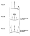
- Figs. 3A-3C are conceptual diagrams illustrating deformation of reflecting mirror 4a attached with the piezoelectric film.
- Fig. 3 A shows the initial state where reflecting mirror 4a has not be deformed, in which state the laser beam is reflected with the same degree of parallelism as the incident direction.
- Fig. 3B shows the case where the piezoelectric film expands.
- the piezoelectric film When a positive voltage is applied, the piezoelectric film expands. As the piezoelectric film expands in the radial direction, reflecting mirror 4a has its curvature changed in response to the tensile force, so that a concave portion is formed. Thus, the parallel incident light is converted to convergent light, with the degree of parallelism changed.
- Fig. 3C shows the case where the piezoelectric film contracts.
- the piezoelectric film contracts.
- reflecting mirror 4a has its curvature changed in response to the tensile force, and a convex portion is formed. Accordingly, the parallel incident light is converted to divergent light, with the degree of parallelism changed.
- reflecting mirror 4a is deformed by means of piezoelectric film 4c to adjust the degree of parallelism of the reflected light. That is, to correct the spherical aberration at objective lens 5, the degree of parallelism is changed by piezoelectric film 4c, as shown by dotted lines in Fig. 1, to change the angle of incidence of the reflected light onto objective lens 5.
- the returned reflected light from disk 6 is detected by photodetector 8, and the level of the voltage to be applied to piezoelectric film 4c is set based on the detected light intensity.
- photodetector 8 a ratio between light intensity at and around the center of the received light and light intensity in the periphery, other than at and around the center, is compared with a prescribed reference value, and the voltage level of the applied voltage is adjusted based on the comparison result.
- the returned reflected light of the laser beam irradiated on the objective lens is used to adjust the incident angle of the reflected light to the objective lens, so that the spherical aberration can be corrected taking account of, not only the thickness of the disk, but also the error in objective lens 5 and others.
- the present invention is not limited thereto. Even in the case where the laser beam directed to the reflecting mirror is divergent light or convergent light, the reflected light can be made to enter the objective lens at a desired angle.
Landscapes
- Physics & Mathematics (AREA)
- Optics & Photonics (AREA)
- Optical Head (AREA)
- Optical Elements Other Than Lenses (AREA)
- Optical Recording Or Reproduction (AREA)
Abstract
Description
Claims (7)
- An optical head device correcting spherical aberration, comprising:said mirror driving unit (4) includinga light emitting diode (1) emitting a laser light;a mirror driving unit (4) for reflecting the laser light received from said light emitting diode (1); anda lens (5) receiving a reflected light from said mirror driving unit (4) and forming a light spot on a surface of a storage medium,
a mirror (4a) reflecting said laser light, and
a piezoelectric element (4c) provided in said mirror (4a) opposite to a surface reflecting said laser light and changing curvature of said mirror (4a),
said mirror driving unit (4) adjusting an angle of incidence of the reflected light onto said lens (5) such that said spherical aberration is corrected at said lens (5) when said lens (5) forms the light spot,
the device further comprising:whereina detector (8) detecting light intensity of the light returned from said lens (5); anda voltage applying circuit (9) setting an applied voltage to be applied to said piezoelectric element (4c) based on the light intensity detected by said detector (8);
said detector (8) compares light intensity at and around the center of said returned light with light intensity in the periphery other than at and around the center, and instructs said voltage applying circuit (9) to adjust said applied voltage based on a result of the comparison,
said piezoelectric element (4c) is attached to said mirror (4a) to form a unimorph structure, and
said piezoelectric element (4c) is arranged in a circular shape on a surface of said mirror (4a) opposite to the surface reflecting said laser light, and expands/contracts in a radial direction to change the curvature of said mirror (4a) to set said reflected light to one of convergent light and divergent light. - An optical head device correcting spherical aberration, comprising:said mirror driving unit (4) includinga light emitting diode (1) emitting a laser light;a mirror driving unit (4) for reflecting the laser light received from said light emitting diode (1); anda lens (5) receiving a reflected light from said mirror driving unit (4) and forming a light spot on a surface of a storage medium;
a mirror (4a) reflecting said laser light, and
a piezoelectric element (4c) provided in said mirror (4a) opposite to a surface reflecting said laser light to change curvature of said mirror (4a),
said mirror driving unit (4) adjusting an angle of incidence of the reflected light onto said lens (5) such that said spherical aberration is corrected at said lens (5) when said lens (5) forms the light spot. - The optical head device according to claim 2, wherein said piezoelectric element (4c) is attached to said mirror (4a) to form a unimorph structure.
- The optical head device according to claim 2, wherein said piezoelectric element (4c) is arranged in a circular shape on a surface of said mirror (4a) opposite to the surface reflecting said laser light, and expands/contracts in a radial direction to change the curvature of said mirror (4a).
- The optical head device according to claim 2, wherein said piezoelectric element (4c) changes the curvature of said mirror (4a) to set said reflected light to one of convergent light and divergent light.
- The optical head device according to claim 2, further comprising:a detector (8) detecting light intensity of the light returned from said lens (5); anda voltage applying circuit (9) setting an applied voltage to be applied to said piezoelectric element (4c) based on the light intensity detected by said detector (8).
- The optical head device according to claim 6, wherein said detector (8) compares light intensity at and around a center of said returned light with light intensity in the periphery other than at and around the center, and instructs said voltage applying circuit (9) to adjust said applied voltage based on a result of the comparison.
Applications Claiming Priority (2)
| Application Number | Priority Date | Filing Date | Title |
|---|---|---|---|
| JP2003379942A JP4042682B2 (en) | 2003-11-10 | 2003-11-10 | Optical head device |
| JP2003379942 | 2003-11-10 |
Publications (2)
| Publication Number | Publication Date |
|---|---|
| EP1530206A2 true EP1530206A2 (en) | 2005-05-11 |
| EP1530206A3 EP1530206A3 (en) | 2007-10-03 |
Family
ID=34431390
Family Applications (1)
| Application Number | Title | Priority Date | Filing Date |
|---|---|---|---|
| EP04026220A Withdrawn EP1530206A3 (en) | 2003-11-10 | 2004-11-04 | Optical head device having deformable reflecting mirror |
Country Status (4)
| Country | Link |
|---|---|
| US (1) | US20050122856A1 (en) |
| EP (1) | EP1530206A3 (en) |
| JP (1) | JP4042682B2 (en) |
| CN (1) | CN100346179C (en) |
Families Citing this family (10)
| Publication number | Priority date | Publication date | Assignee | Title |
|---|---|---|---|---|
| CN100496855C (en) * | 2005-08-19 | 2009-06-10 | 中国科学院光电技术研究所 | Precision Machining Laser Cutting Machine |
| CN100595627C (en) * | 2007-04-16 | 2010-03-24 | 三菱电机株式会社 | Deformable mirror and laser processing device using deformable mirror |
| JP5076232B2 (en) * | 2007-05-09 | 2012-11-21 | 船井電機株式会社 | Variable shape mirror, optical pickup device |
| US8320229B2 (en) * | 2009-11-12 | 2012-11-27 | Hitachi Consumer Electronics Co., Ltd. | Variable mirror actuator and optical disc drive |
| DE102010028111B4 (en) | 2010-04-22 | 2016-01-21 | Technische Universität Dresden | Micromechanical element |
| CN102324028A (en) * | 2011-06-09 | 2012-01-18 | 高椿明 | Optic reverse identification system with cat eye structure base on piezoelectric device |
| CN102222378A (en) * | 2011-06-23 | 2011-10-19 | 高椿明 | Modulated reflecting type optical access control system |
| CN103848393B (en) * | 2013-12-04 | 2016-01-13 | 中国科学院长春光学精密机械与物理研究所 | A kind of adjustment of the ultraprecise depth of parallelism for electrostatic induction technology and detection system |
| CN117215129A (en) * | 2023-08-25 | 2023-12-12 | 维沃移动通信有限公司 | Housing and electronic equipment |
| CN119362161B (en) * | 2024-12-23 | 2025-05-13 | 中国科学院长春光学精密机械与物理研究所 | Integrated semiconductor laser based on beam angle control and preparation method thereof |
Family Cites Families (18)
| Publication number | Priority date | Publication date | Assignee | Title |
|---|---|---|---|---|
| US5202875A (en) * | 1991-06-04 | 1993-04-13 | International Business Machines Corporation | Multiple data surface optical data storage system |
| JPH09152505A (en) * | 1995-11-30 | 1997-06-10 | Sharp Corp | Deformable mirror, manufacturing method thereof, optical device, and recording / reproducing device |
| WO1997035306A1 (en) * | 1996-03-18 | 1997-09-25 | Seiko Epson Corporation | Optical head and optical recorder |
| JPH1031107A (en) * | 1996-07-16 | 1998-02-03 | Sharp Corp | Deformable mirror, optical device, and recording / reproducing device |
| JPH10188319A (en) * | 1996-12-26 | 1998-07-21 | Sharp Corp | Deformable mirror and optical recording / reproducing apparatus using the deformable mirror |
| JP3545233B2 (en) * | 1998-12-08 | 2004-07-21 | シャープ株式会社 | Spherical aberration detection device and optical pickup device |
| TW442783B (en) * | 1999-07-09 | 2001-06-23 | Ind Tech Res Inst | Folding mirror |
| US6967916B2 (en) * | 2000-10-10 | 2005-11-22 | Matsushita Electric Industrial Co., Ltd. | Optical head apparatus, optical information recording and reproducing apparatus, method for detecting aberration and method for adjusting optical head apparatus |
| EP1197767A3 (en) * | 2000-10-11 | 2004-12-22 | Olympus Optical Co., Ltd. | Optical apparatus comprising variable mirror |
| JP3827940B2 (en) * | 2000-11-15 | 2006-09-27 | シャープ株式会社 | Aberration detection device and optical pickup device |
| JP2002358677A (en) * | 2001-05-28 | 2002-12-13 | Hitachi Ltd | Optical head and optical disk device |
| JP2003123282A (en) * | 2001-08-06 | 2003-04-25 | Sharp Corp | Focus adjustment method and optical pickup device |
| JP4373036B2 (en) * | 2001-08-31 | 2009-11-25 | パイオニア株式会社 | Optical pickup |
| JP2003157567A (en) * | 2001-11-20 | 2003-05-30 | Olympus Optical Co Ltd | Deformable mirror for optical pickup |
| CN1639783A (en) * | 2001-12-06 | 2005-07-13 | 皇家飞利浦电子股份有限公司 | Optical scanning device |
| JP4376786B2 (en) * | 2002-10-23 | 2009-12-02 | コーニンクレッカ フィリップス エレクトロニクス エヌ ヴィ | Spherical aberration detection |
| JP2004347753A (en) * | 2003-05-21 | 2004-12-09 | Matsushita Electric Ind Co Ltd | Variable shape mirror element, method of manufacturing variable shape mirror element, variable shape mirror unit, and optical pickup |
| WO2005024809A2 (en) * | 2003-09-04 | 2005-03-17 | Matsushita Electric Industrial Co., Ltd. | Optical pick-up aberration correcting mirror, aberration correcting method and optical pick-up |
-
2003
- 2003-11-10 JP JP2003379942A patent/JP4042682B2/en not_active Expired - Fee Related
-
2004
- 2004-11-04 EP EP04026220A patent/EP1530206A3/en not_active Withdrawn
- 2004-11-09 US US10/984,157 patent/US20050122856A1/en not_active Abandoned
- 2004-11-10 CN CNB200410095725XA patent/CN100346179C/en not_active Expired - Fee Related
Also Published As
| Publication number | Publication date |
|---|---|
| JP4042682B2 (en) | 2008-02-06 |
| CN1616994A (en) | 2005-05-18 |
| US20050122856A1 (en) | 2005-06-09 |
| CN100346179C (en) | 2007-10-31 |
| EP1530206A3 (en) | 2007-10-03 |
| JP2005141876A (en) | 2005-06-02 |
Similar Documents
| Publication | Publication Date | Title |
|---|---|---|
| US6836459B2 (en) | Optical pickup device | |
| JP2002157750A (en) | Optical disk apparatus and information recording / reproducing method | |
| US6108139A (en) | Optical head device and method of information reproduction using the same | |
| JP4088472B2 (en) | Optical disk device | |
| KR100327367B1 (en) | micro-mirror device and optical pick-up system using the same | |
| US20050122856A1 (en) | Optical head device having deformable reflecting mirror | |
| US6496466B1 (en) | Folding mirror structure | |
| US5132534A (en) | Optical pickup with position adjusting means | |
| US6876622B2 (en) | Anamorphic prism, optical head and optical recording/reproduction device | |
| KR100486818B1 (en) | Device for the writing and/or reading of optical recording media of various structures | |
| JPH0434740A (en) | Optical head | |
| CN119495326B (en) | Optical disk drive with single servo layer and multiple recording layers, memory and electronic equipment | |
| JP2000030290A (en) | Optical head device and optical disk recording / reproducing device | |
| JP2000048382A (en) | Recording medium recording / reproducing device and optical pickup | |
| EP1895529A1 (en) | Aberration correction element, optical pickup and optical disc apparatus | |
| KR100421011B1 (en) | Optical pickup comprising a polygon prism and method of compensating optical axes using the same | |
| US20110158078A1 (en) | Optical pickup device and focus jump method | |
| US20080231928A1 (en) | Optical Scanning Device with Low Building Height | |
| US8341657B2 (en) | Lens driving mechanism for optical pickup and optical disc apparatus | |
| JP2004233410A (en) | Wavefront aberration correction device and optical pickup | |
| KR100551118B1 (en) | Optical Pick-up Apparatus | |
| JP2001052365A (en) | Light head | |
| KR19990055074A (en) | Optical pickup device | |
| US20060140071A1 (en) | Objective lens optical part for optical pickup device and focusing method using the same | |
| JP2004319064A (en) | Optical head device and optical recording medium driving device |
Legal Events
| Date | Code | Title | Description |
|---|---|---|---|
| PUAI | Public reference made under article 153(3) epc to a published international application that has entered the european phase |
Free format text: ORIGINAL CODE: 0009012 |
|
| AK | Designated contracting states |
Kind code of ref document: A2 Designated state(s): AT BE BG CH CY CZ DE DK EE ES FI FR GB GR HU IE IS IT LI LU MC NL PL PT RO SE SI SK TR |
|
| AX | Request for extension of the european patent |
Extension state: AL HR LT LV MK YU |
|
| PUAL | Search report despatched |
Free format text: ORIGINAL CODE: 0009013 |
|
| AK | Designated contracting states |
Kind code of ref document: A3 Designated state(s): AT BE BG CH CY CZ DE DK EE ES FI FR GB GR HU IE IS IT LI LU MC NL PL PT RO SE SI SK TR |
|
| AX | Request for extension of the european patent |
Extension state: AL HR LT LV MK YU |
|
| 17P | Request for examination filed |
Effective date: 20080129 |
|
| 17Q | First examination report despatched |
Effective date: 20080408 |
|
| AKX | Designation fees paid |
Designated state(s): DE FR GB |
|
| STAA | Information on the status of an ep patent application or granted ep patent |
Free format text: STATUS: THE APPLICATION IS DEEMED TO BE WITHDRAWN |
|
| 18D | Application deemed to be withdrawn |
Effective date: 20100601 |