EP1530031A1 - Powder and granular material metering device - Google Patents
Powder and granular material metering device Download PDFInfo
- Publication number
- EP1530031A1 EP1530031A1 EP03736142A EP03736142A EP1530031A1 EP 1530031 A1 EP1530031 A1 EP 1530031A1 EP 03736142 A EP03736142 A EP 03736142A EP 03736142 A EP03736142 A EP 03736142A EP 1530031 A1 EP1530031 A1 EP 1530031A1
- Authority
- EP
- European Patent Office
- Prior art keywords
- powder body
- metering
- opening
- metering container
- container
- Prior art date
- Legal status (The legal status is an assumption and is not a legal conclusion. Google has not performed a legal analysis and makes no representation as to the accuracy of the status listed.)
- Withdrawn
Links
- 239000000843 powder Substances 0.000 title claims abstract description 86
- 239000008187 granular material Substances 0.000 title 1
- 229920003002 synthetic resin Polymers 0.000 abstract description 4
- 239000000057 synthetic resin Substances 0.000 abstract description 4
- 239000002994 raw material Substances 0.000 abstract description 3
- 230000002093 peripheral effect Effects 0.000 description 2
- 238000007599 discharging Methods 0.000 description 1
- 230000000694 effects Effects 0.000 description 1
- 239000000835 fiber Substances 0.000 description 1
- 239000010419 fine particle Substances 0.000 description 1
- 238000001746 injection moulding Methods 0.000 description 1
- 238000000465 moulding Methods 0.000 description 1
- 238000012856 packing Methods 0.000 description 1
Images

Classifications
-
- G—PHYSICS
- G01—MEASURING; TESTING
- G01F—MEASURING VOLUME, VOLUME FLOW, MASS FLOW OR LIQUID LEVEL; METERING BY VOLUME
- G01F13/00—Apparatus for measuring by volume and delivering fluids or fluent solid materials, not provided for in the preceding groups
-
- G—PHYSICS
- G01—MEASURING; TESTING
- G01F—MEASURING VOLUME, VOLUME FLOW, MASS FLOW OR LIQUID LEVEL; METERING BY VOLUME
- G01F13/00—Apparatus for measuring by volume and delivering fluids or fluent solid materials, not provided for in the preceding groups
- G01F13/001—Apparatus for measuring by volume and delivering fluids or fluent solid materials, not provided for in the preceding groups for fluent solid material
-
- G—PHYSICS
- G01—MEASURING; TESTING
- G01F—MEASURING VOLUME, VOLUME FLOW, MASS FLOW OR LIQUID LEVEL; METERING BY VOLUME
- G01F11/00—Apparatus requiring external operation adapted at each repeated and identical operation to measure and separate a predetermined volume of fluid or fluent solid material from a supply or container, without regard to weight, and to deliver it
- G01F11/28—Apparatus requiring external operation adapted at each repeated and identical operation to measure and separate a predetermined volume of fluid or fluent solid material from a supply or container, without regard to weight, and to deliver it with stationary measuring chambers having constant volume during measurement
- G01F11/282—Apparatus requiring external operation adapted at each repeated and identical operation to measure and separate a predetermined volume of fluid or fluent solid material from a supply or container, without regard to weight, and to deliver it with stationary measuring chambers having constant volume during measurement for fluent solid material not provided for in G01F11/34, G01F11/40, G01F11/46
-
- G—PHYSICS
- G01—MEASURING; TESTING
- G01F—MEASURING VOLUME, VOLUME FLOW, MASS FLOW OR LIQUID LEVEL; METERING BY VOLUME
- G01F11/00—Apparatus requiring external operation adapted at each repeated and identical operation to measure and separate a predetermined volume of fluid or fluent solid material from a supply or container, without regard to weight, and to deliver it
- G01F11/28—Apparatus requiring external operation adapted at each repeated and identical operation to measure and separate a predetermined volume of fluid or fluent solid material from a supply or container, without regard to weight, and to deliver it with stationary measuring chambers having constant volume during measurement
- G01F11/36—Apparatus requiring external operation adapted at each repeated and identical operation to measure and separate a predetermined volume of fluid or fluent solid material from a supply or container, without regard to weight, and to deliver it with stationary measuring chambers having constant volume during measurement with supply or discharge valves of the rectilinearly-moved slide type
- G01F11/40—Apparatus requiring external operation adapted at each repeated and identical operation to measure and separate a predetermined volume of fluid or fluent solid material from a supply or container, without regard to weight, and to deliver it with stationary measuring chambers having constant volume during measurement with supply or discharge valves of the rectilinearly-moved slide type for fluent solid material
Definitions
- the present invention relates to a powder body metering apparatus which is preferable for metering a powder body such as a synthetic resin raw material or the like.
- a conventional metering apparatus has a metering container including an inlet in an upper end and a horizontal outlet in an upper side portion, a switch valve for opening and closing the inlet of the metering container, and an upward discharge pipe connected to the horizontal outlet, and is structured such that the metering container has an upper tube, a lower tube fitted to and covered on the upper tube so as to be freely adjusted in a vertical position, and a porous body provided in a lower end of the lower tube and not allowing a powder body having a set magnitude to pass through but allowing a gas to pass through (refer to Japanese Unexamined Patent Publication No. 2002-148092).
- the conventional metering apparatus mentioned above has the following disadvantage.
- the porous body (which does not allow the powder body having the set magnitude to pass through but allows the gas to pass through) is provided in the lower end of the lower tube, it is impossible to flow the powder body into the metering container from an external portion of the porous body, so that there is a disadvantage that it is impossible to use the metering container itself as a part of a transport pipe (in other words, it is impossible to feed the powder body within the metering container of another metering apparatus to a reservoir tank or the like via the metering container).
- the present invention employs the following means for solving the disadvantage mentioned above.
- the present invention achieves the following effect on the basis of the structures mentioned above.
- a vertical guide tube 3 is connected to an outlet 2 of a reservoir hopper 1 reserving a powder body, and a metering apparatus 31 is mounted to a lower end of the guide tube 3.
- the metering apparatus 31 has a metering container 32 including an inlet 33 in an upper end, and a switch valve 36 opening and closing the inlet 33 of the metering container 32 and connected to a lower end of the guide tube 3.
- the metering container 32 is variable in an internal capacity on the basis of a structure described below in detail, and has a first opening 49 in a lower portion and a second opening 50 in a desired portion, a lower portion in the present embodiment.
- the metering container 32 has an upper tube 21 with a vertical axis and with the inlet 33 provided in an upper end, and a lower tube 22 provided to the upper tube 21 so as to he freely adjusted in a vertical position.
- the lower member 22 has a tube portion 22a with a vertical axis, and a hollow closed-end circular truncated cone portion 22b provided in a lower portion of the tube portion 22a and open in an upper portion.
- Two through holes 46 are formed in a side wall of the circular truncated cone portion 22b, upward short tubes 47 are connected to the through holes 46, an upper end opening of one short tube 47 is formed as a first opening 49, and an upper end opening of another short tube 47 is formed as a second opening 50.
- a thread hole 23 with a horizontal axis is formed in an upper portion of the tube portion 22a of the lower member 22, a screw 24 is engaged with the thread hole 23, and the lower member 22 is fixed to the upper tube 21 by pressing a leading end of the screw 24 to the upper tube 21.
- the lower member 22 can be moved vertically by loosening the screw 24.
- the structure may be made such that annular grooves are formed on an outer peripheral surface of the upper tube 21 at a predetermined interval in a height direction, whereby the leading end of the screw 24 is fitted to the annular groove, and the lower member 22 is firmly fixed.
- the powder body within the metering container 32 is discharged from the first opening 49, and the other metering apparatus, transport pipe, gas pump (not shown) and the like are connected such that the gas or the powder body fed from the other metering apparatus (not shown) enters from the second opening 50.
- the switch valve 36 has a casing 40 in which an inlet 41 is provided in an upper portion and an outlet 42 lapping over the inlet 41 in a plan view is provided in a lower portion, and a slide plate 44 horizontally slidable in a direction vertical to the paper surface in Fig. 1 with respect to the casing 40 and having a through hole 45.
- an internal capacity of the metering container 32 is made to a set value by adjusting a height position of the lower member 22 with respect to the upper tube 21.
- a height position of the lower member 22 is adjusted by adjusting a height position of the lower member 22 with respect to the upper tube 21.
- it is possible to prevent a part of the powder body entering into the metering container 32 from running over into the short tube 47, or it is possible to approximately define an overflowing amount even if the powder body runs over by designing a shape (an angle ⁇ in Fig. 1) of the circular truncated cone portion 22b with taking an angle of repose or the powder body or the like into consideration, it is preferable to determine a capacity of the metering container 32 taking the condition into consideration.
- the powder body flows into the metering container 32, and an inner side of the metering container 32 is filled with the powder body.
- the powder body within the metering container 32 is discharged from the first opening 49 and is fed to a predetermined place.
- the powder body outlet of the metering container of the other metering apparatus is connected to the second opening 50, whereby the powder body transport system is constructed, the powder body within the metering container of the other metering apparatus can be transported to the predetermined place via the illustrated metering container 32, by finishing the discharge of the powder body within the metering container 32, thereafter keeping the switch valve 36 in the closed state, filling the powder body in the metering container of the other metering apparatus and thereafter generating the gas stream toward the first opening 49 from the second opening 50.
- the metering container 32 can be utilized as a part of the transport pipe.
- the lower member 22 has a tube portion 22a with a vertical axis, and an upward opened closed-end slope tube portion 22c which is connected to a lower end of the tube portion 22a and has an inclined axis.
- a through hole 46 is formed in an upper side wall of the tube portion 22a, and an upward curved short tube 52 is connected to the through hole 46.
- An upper end opening of the short tube 52 is formed as a second opening 50.
- a through hole 46 is formed in a side peripheral wall of the slope tube portion 22c, an upward short tube 47 is connected to the through hole 46, and an upper end opening of the short tube 47 is formed as a first opening 49.
- the powder body within the metering container 32 flows out from the first opening 49, and the other metering apparatus, transport pipe, gas pump (not shown) and the like are connected such that the gas or the powder body fed from the other metering apparatus (not shown) enters from the second opening 50.
- An operation of the second embodiment is the same as the operation of the first embodiment.
- a powder body discharge port 54 is formed in a lower portion of the circular truncated cone portion 22b of the lower member 22, an outward protruding flange 55 is formed in an edge portion of the powder body discharge port 54, and a closing member 57 is provided in the flange so as to be freely swingable horizontally via a support shaft 56 with a vertical axis.
- the closing member 57 can horizontally swing between a position at which the powder body discharge port 54 is completely elpsed, and a position at which the powder body discharge port 54 is completely opened, thereby closing and opening the powder body discharge port 54.
- the closing member 57 is structured such as to be locked to the circular truncated cone portion 22b by a known lock apparatus (not shown) at the position at which the powder body discharge port 54 is completely closed.
- a weight or the like of the powder body metered by the metering container 32 can be easily measured and confirmed by opening the powder body discharge port 54 so as to discharge the powder body within the metering container 32 from the powder body discharge port 54.
- An operation of the third embodiment is the same as the operation of the first embodiment.
- a powder body discharge port 54 is formed in a lower portion of the slope tube portion 22c, an outward protruding flange 55 is formed in an edge portion of the powder body discharge port 54, and a closing member 57 is provided in the flange 55 so as to be freely swingable horizontally via a support shaft 56 with a vertical axis.
- the closing member 57 can horizontally swing between a position at which the powder body discharge port 54 is completely closed, and a position at which the powder body discharge port 54 is completely opened, thereby closing and opening the powder body discharge port 54.
- the closing member 57 is structured such as to be locked to the slope tube portion 22c by a known lock apparatus (not shown) at the position at which the powder body discharge port 54 is completely closed.
- a weight or the like of the powder body metered by the metering container 32 can be easily measured and confirmed by opening the powder body discharge port 54 so as to discharge the powder body within the metering container 32 from the powder body discharge port 54.
- An operation of the fourth embodiment is the same as the operation of the first embodiment.
- the present invention is suitable for metering and supplying a powder body of a synthetic resin raw material to an injection molding machine, in a molding system of a synthetic resin product.
Landscapes
- Physics & Mathematics (AREA)
- Fluid Mechanics (AREA)
- General Physics & Mathematics (AREA)
- Filling Or Emptying Of Bunkers, Hoppers, And Tanks (AREA)
- Processing And Handling Of Plastics And Other Materials For Molding In General (AREA)
Abstract
Description
- The present invention relates to a powder body metering apparatus which is preferable for metering a powder body such as a synthetic resin raw material or the like.
- The following structure has been conventionally known as this kind of metering apparatus.
- A conventional metering apparatus has a metering container including an inlet in an upper end and a horizontal outlet in an upper side portion, a switch valve for opening and closing the inlet of the metering container, and an upward discharge pipe connected to the horizontal outlet, and is structured such that the metering container has an upper tube, a lower tube fitted to and covered on the upper tube so as to be freely adjusted in a vertical position, and a porous body provided in a lower end of the lower tube and not allowing a powder body having a set magnitude to pass through but allowing a gas to pass through (refer to Japanese Unexamined Patent Publication No. 2002-148092).
- The conventional metering apparatus mentioned above has the following disadvantage.
- Since the porous body (which does not allow the powder body having the set magnitude to pass through but allows the gas to pass through) is provided in the lower end of the lower tube, it is impossible to flow the powder body into the metering container from an external portion of the porous body, so that there is a disadvantage that it is impossible to use the metering container itself as a part of a transport pipe (in other words, it is impossible to feed the powder body within the metering container of another metering apparatus to a reservoir tank or the like via the metering container).
- The present invention employs the following means for solving the disadvantage mentioned above.
- (1) In accordance with a first aspect of the present invention, there is provided a powder body metering apparatus having a metering container including an inlet in an upper end, and a switch valve for opening and closing the inlet of the metering container, wherein an internal capacity of the metering container is variable, and has a first opening in a lower portion and a second opening in a desired portion.
- (2) In accordance with a second aspect of the present invention, there is provided a powder body metering apparatus, wherein a powder body discharge port is formed in the lower portion of the metering container, and the powder body discharge port is freely opened and closed by a closing member.
-
- The present invention achieves the following effect on the basis of the structures mentioned above.
- (1) In accordance with the invention of the first aspect, the powder body within the metering container can be discharged from the first opening by generating the gas flow from the second opening toward the first opening, and the powder body within the metering container can be discharged from the second opening by generating the gas flow from the first opening toward the second opening. Accordingly, since the metering container itself can be used as a part of the transport pipe for the powder body, the metering container can be built in a currently widely used powder body transport system so as to be effectively used as the metering apparatus doubling as the transport pipe.
- (2) In accordance with the invention of the second aspect, since the powder body can be discharged from the powder body discharge port by opening the powder body discharge port, it is possible to easily meter and confirm the weight or the like of the powder body metered by the metering container.
-
-
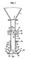
- Fig. 1 is a cross sectional view of a main portion showing a first embodiment in accordance with the present invention;
- Fig. 2 is a cross sectional view of a main portion showing a second embodiment in accordance with the present invention;
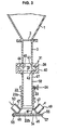
- Fig. 3 is a cross sectional view of a main portion showing a third embodiment in accordance with the present invention; and
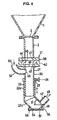
- Fig. 4 is a cross sectional view of a main portion showing a fourth embodiment in accordance with the present invention.
-
- A description will be given below of four embodiments in accordance with the present invention.
- In this case, the same members will be shown by the same reference numerals in this description.
- A vertical guide tube 3 is connected to an outlet 2 of a reservoir hopper 1 reserving a powder body, and a
metering apparatus 31 is mounted to a lower end of the guide tube 3. - The
metering apparatus 31 has ametering container 32 including an inlet 33 in an upper end, and aswitch valve 36 opening and closing the inlet 33 of themetering container 32 and connected to a lower end of the guide tube 3. Themetering container 32 is variable in an internal capacity on the basis of a structure described below in detail, and has afirst opening 49 in a lower portion and asecond opening 50 in a desired portion, a lower portion in the present embodiment. - The
metering container 32 has anupper tube 21 with a vertical axis and with the inlet 33 provided in an upper end, and alower tube 22 provided to theupper tube 21 so as to he freely adjusted in a vertical position. - The
lower member 22 has atube portion 22a with a vertical axis, and a hollow closed-end circular truncatedcone portion 22b provided in a lower portion of thetube portion 22a and open in an upper portion. Two throughholes 46 are formed in a side wall of the circular truncatedcone portion 22b, upwardshort tubes 47 are connected to the throughholes 46, an upper end opening of oneshort tube 47 is formed as afirst opening 49, and an upper end opening of anothershort tube 47 is formed as a second opening 50. - A
thread hole 23 with a horizontal axis is formed in an upper portion of thetube portion 22a of thelower member 22, ascrew 24 is engaged with thethread hole 23, and thelower member 22 is fixed to theupper tube 21 by pressing a leading end of thescrew 24 to theupper tube 21. On the other hand, thelower member 22 can be moved vertically by loosening thescrew 24. In this case, the structure may be made such that annular grooves are formed on an outer peripheral surface of theupper tube 21 at a predetermined interval in a height direction, whereby the leading end of thescrew 24 is fitted to the annular groove, and thelower member 22 is firmly fixed. - In the present embodiment, the powder body within the
metering container 32 is discharged from thefirst opening 49, and the other metering apparatus, transport pipe, gas pump (not shown) and the like are connected such that the gas or the powder body fed from the other metering apparatus (not shown) enters from the second opening 50. - The
switch valve 36 has acasing 40 in which aninlet 41 is provided in an upper portion and anoutlet 42 lapping over theinlet 41 in a plan view is provided in a lower portion, and aslide plate 44 horizontally slidable in a direction vertical to the paper surface in Fig. 1 with respect to thecasing 40 and having a through hole 45. - Next, a description will be given of a first operation of the first embodiment.
- First, an internal capacity of the
metering container 32 is made to a set value by adjusting a height position of thelower member 22 with respect to theupper tube 21. In this case, since it is possible to prevent a part of the powder body entering into themetering container 32 from running over into theshort tube 47, or it is possible to approximately define an overflowing amount even if the powder body runs over, by designing a shape (an angle α in Fig. 1) of the circular truncatedcone portion 22b with taking an angle of repose or the powder body or the like into consideration, it is preferable to determine a capacity of themetering container 32 taking the condition into consideration. - Thereafter, when opening the
check valve 36 after charging the powder body to the reservoir hopper 1, the powder body flows into themetering container 32, and an inner side of themetering container 32 is filled with the powder body. - Thereafter, the
check valve 36 is closed. - Thereafter, by generating the gas stream toward the
first opening 49 from the second opening 50, the powder body within themetering container 32 is discharged from thefirst opening 49 and is fed to a predetermined place. - Thereafter, the
check valve 36 is again opened. - The same operations are carried out sequentially.
- Next, a description will be given of a second operation of the first embodiment.
- Since the powder body outlet of the metering container of the other metering apparatus is connected to the second opening 50, whereby the powder body transport system is constructed, the powder body within the metering container of the other metering apparatus can be transported to the predetermined place via the illustrated
metering container 32, by finishing the discharge of the powder body within themetering container 32, thereafter keeping theswitch valve 36 in the closed state, filling the powder body in the metering container of the other metering apparatus and thereafter generating the gas stream toward thefirst opening 49 from the second opening 50. In short, themetering container 32 can be utilized as a part of the transport pipe. - The
lower member 22 has atube portion 22a with a vertical axis, and an upward opened closed-endslope tube portion 22c which is connected to a lower end of thetube portion 22a and has an inclined axis. - A through
hole 46 is formed in an upper side wall of thetube portion 22a, and an upward curvedshort tube 52 is connected to the throughhole 46. An upper end opening of theshort tube 52 is formed as a second opening 50. Further, athrough hole 46 is formed in a side peripheral wall of theslope tube portion 22c, an upwardshort tube 47 is connected to the throughhole 46, and an upper end opening of theshort tube 47 is formed as afirst opening 49. - It is possible to prevent a part of the powder body entering into the
metering container 32 from running over into theshort tube 47, or it is possible to approximately define an overflowing amount even if the powder body runs over, by designing an angle of incline (an angle α in Fig. 2) of theslope tube portion 22c with taking an angle of repose or the like into consideration. Further, a part of the powder body entering into themetering container 32 runs over into theshort tube 52, however, the overflowing amount is determined on the basis of the kind of the powder body. Under these circumstances, themetering container 32 functions as a metering container. - In the present embodiment, the powder body within the
metering container 32 flows out from thefirst opening 49, and the other metering apparatus, transport pipe, gas pump (not shown) and the like are connected such that the gas or the powder body fed from the other metering apparatus (not shown) enters from the second opening 50. - An operation of the second embodiment is the same as the operation of the first embodiment.
- A powder
body discharge port 54 is formed in a lower portion of the circular truncatedcone portion 22b of thelower member 22, an outward protrudingflange 55 is formed in an edge portion of the powderbody discharge port 54, and aclosing member 57 is provided in the flange so as to be freely swingable horizontally via asupport shaft 56 with a vertical axis. Theclosing member 57 can horizontally swing between a position at which the powderbody discharge port 54 is completely elpsed, and a position at which the powderbody discharge port 54 is completely opened, thereby closing and opening the powderbody discharge port 54. In this case, theclosing member 57 is structured such as to be locked to the circular truncatedcone portion 22b by a known lock apparatus (not shown) at the position at which the powderbody discharge port 54 is completely closed. In accordance with the structure mentioned above, a weight or the like of the powder body metered by themetering container 32 can be easily measured and confirmed by opening the powderbody discharge port 54 so as to discharge the powder body within themetering container 32 from the powderbody discharge port 54. - An operation of the third embodiment is the same as the operation of the first embodiment.
- A powder
body discharge port 54 is formed in a lower portion of theslope tube portion 22c, an outward protrudingflange 55 is formed in an edge portion of the powderbody discharge port 54, and aclosing member 57 is provided in theflange 55 so as to be freely swingable horizontally via asupport shaft 56 with a vertical axis. The closingmember 57 can horizontally swing between a position at which the powderbody discharge port 54 is completely closed, and a position at which the powderbody discharge port 54 is completely opened, thereby closing and opening the powderbody discharge port 54. In this case, the closingmember 57 is structured such as to be locked to theslope tube portion 22c by a known lock apparatus (not shown) at the position at which the powderbody discharge port 54 is completely closed. In accordance with the structure mentioned above, a weight or the like of the powder body metered by themetering container 32 can be easily measured and confirmed by opening the powderbody discharge port 54 so as to discharge the powder body within themetering container 32 from the powderbody discharge port 54. - An operation of the fourth embodiment is the same as the operation of the first embodiment.
- A description will be given below of modified embodiments.
- (1) The powder body includes a fine particle, a granular body, a micro thin piece, a short fiber piece, a sliver and the like.
- (2) The
metering apparatus 31 is optionally used. - (3) The metering apparatus may be optionally structured as far as the internal capacity is variable.
- (4) In the case of the powder body having a large
bulk density in the second or fourth embodiment, the
powder body can be smoothly discharged by discharging
the powder body from the
first opening 49 in the lower portion. On the other hand, in the case of the powder body having a small bulk density, the powder body may be discharged from thesecond opening 50. In this case, even in the case of the powder body having the large bulk density, the powder body can be discharged from thesecond opening 50 by increasing a gas flow speed. - (5) The mechanism of freely opening and closing
the closing
member 57 with respect to the powderbody discharge port 54 is optionally structured. In this case, in order to improve an airtightness between the powderbody discharge port 54 and the closingmember 57, it is preferable to mount an annular packing to the edge of the powderbody discharge port 54. - (6) It goes without saying that the porous body
(which does not allow the powder body having the set
magnitude to pass through but allows the gas to pass
through) is provided in one of the
first opening 49 and thesecond opening 50, whereby the opening provided with the porous body is set as the gas inflow port and another opening is set as the powder body outlet, and accordingly the metering apparatus of the powder body can be used. -
- The present invention is suitable for metering and supplying a powder body of a synthetic resin raw material to an injection molding machine, in a molding system of a synthetic resin product.
Claims (2)
- A powder body metering apparatus comprises a metering container including an inlet in an upper end, and a switch valve for opening and closing the inlet of the metering container, wherein an internal capacity of said metering container is variable, and has a first opening in a lower portion and a second opening in a desired portion.
- A powder body metering apparatus as claimed in claim 1, wherein a powder body discharge port is formed in the lower portion of the metering container, and the powder body discharge port is freely opened and closed by a closing member.
Applications Claiming Priority (5)
| Application Number | Priority Date | Filing Date | Title |
|---|---|---|---|
| JP2002196602 | 2002-07-05 | ||
| JP2002196604A JP4000021B2 (en) | 2002-07-05 | 2002-07-05 | Powder measuring device |
| JP2002196602A JP4619612B2 (en) | 2002-07-05 | 2002-07-05 | Powder measuring device |
| JP2002196604 | 2002-07-05 | ||
| PCT/JP2003/007381 WO2004005863A1 (en) | 2002-07-05 | 2003-06-10 | Powder and granular material metering device |
Publications (1)
| Publication Number | Publication Date |
|---|---|
| EP1530031A1 true EP1530031A1 (en) | 2005-05-11 |
Family
ID=30117387
Family Applications (1)
| Application Number | Title | Priority Date | Filing Date |
|---|---|---|---|
| EP03736142A Withdrawn EP1530031A1 (en) | 2002-07-05 | 2003-06-10 | Powder and granular material metering device |
Country Status (6)
| Country | Link |
|---|---|
| US (1) | US7472808B2 (en) |
| EP (1) | EP1530031A1 (en) |
| KR (1) | KR101057261B1 (en) |
| CN (1) | CN100365394C (en) |
| TW (1) | TWI271512B (en) |
| WO (1) | WO2004005863A1 (en) |
Families Citing this family (10)
| Publication number | Priority date | Publication date | Assignee | Title |
|---|---|---|---|---|
| US20110000938A2 (en) * | 2007-05-25 | 2011-01-06 | Shionogi & Co., Ltd. | Powder material supply device |
| CN103848224B (en) * | 2012-11-30 | 2016-12-21 | 深圳市龙澄高科技环保有限公司 | A kind of flexible duct metering feeding device for heterogeneous body soft solid materials |
| CN103396822B (en) * | 2013-07-31 | 2015-05-20 | 神华集团有限责任公司 | Batching-quantitative discharging system, device for preparing oil from coal in direct liquefaction manner and discharging method |
| US10012484B2 (en) | 2014-03-03 | 2018-07-03 | Adr International Limited | Method of improving the accuracy of rifle ammunition |
| CA2904286C (en) | 2014-11-04 | 2021-10-19 | Cnh Industrial Canada, Ltd. | Ringed meter rollers and slide cutoff system |
| CA3093261C (en) | 2014-11-04 | 2022-07-26 | Cnh Industrial Canada, Ltd. | Ringed meter rollers and slide cutoff system |
| CN107298316B (en) * | 2016-10-20 | 2023-06-20 | 佛山市顺德区美的电热电器制造有限公司 | Material conveying device, kitchen storage device and cooking utensil |
| CN107265136A (en) * | 2017-06-28 | 2017-10-20 | 中航锂电(江苏)有限公司 | A kind of lithium ion battery closes the slurry efficient blanking device of powder |
| KR102579910B1 (en) * | 2021-08-18 | 2023-09-15 | 홍순영 | Volume Measuring Machine |
| CN118080776B (en) * | 2024-04-17 | 2024-07-05 | 潍坊晟林铸造机械有限公司 | Double auxiliary material adding type metering rechecking sand mixer |
Family Cites Families (21)
| Publication number | Priority date | Publication date | Assignee | Title |
|---|---|---|---|---|
| US868641A (en) * | 1907-06-03 | 1907-10-22 | Louis B Clark | Measuring device. |
| US1891038A (en) * | 1930-03-24 | 1932-12-13 | Barros Ramon | Automatic filler |
| US2588206A (en) * | 1947-07-23 | 1952-03-04 | Virgil R Clark | Dispenser having an inlet and an outlet valve for measuring the quantities dispensed |
| US3140018A (en) * | 1962-10-15 | 1964-07-07 | Theodore A Miller | Powder dispensing unit |
| JPS5116069A (en) * | 1974-07-30 | 1976-02-09 | Kitagawa Iron Works Co | YOSEKI KIRYOKI |
| US4002268A (en) * | 1975-03-19 | 1977-01-11 | Mckinney Harold D | Volumetric filling system |
| JPS5252960A (en) * | 1975-10-27 | 1977-04-28 | Tadashi Iijima | Device for quantitatively supplying coloring material |
| US4505407A (en) * | 1983-03-07 | 1985-03-19 | Francis Tool Company | Volumetric measure for granular material |
| US4893966A (en) * | 1987-07-07 | 1990-01-16 | Franz Roehl | Lock apparatus for introducing dry granular materials into a pneumatic conveying conduit and spray gun for such materials |
| JP2821607B2 (en) * | 1989-02-14 | 1998-11-05 | 日清製粉株式会社 | Grain counting device |
| JPH0396473A (en) | 1989-09-07 | 1991-04-22 | Toshiba Corp | Automatic course control device |
| JPH0545525A (en) | 1991-08-15 | 1993-02-23 | Showa Electric Wire & Cable Co Ltd | Optical fiber cable |
| US5542583A (en) * | 1994-03-01 | 1996-08-06 | Brother's Gourmet Coffee, Inc. | Dual chamber vacuum storage and dispenser for coffee beans |
| DK0681164T3 (en) * | 1994-05-06 | 2001-04-30 | Nestle Sa | Dosage system for a powdered product |
| SE9603063D0 (en) * | 1996-08-23 | 1996-08-23 | Astra Ab | Device and method for measuring a particulate substance and apparatus comprising a plurality of such devices |
| JPH112552A (en) | 1997-06-11 | 1999-01-06 | Dkk Corp | Flow measurement device |
| FR2771721B1 (en) * | 1997-12-02 | 2000-02-18 | Lucien Vidal | DEVICE FOR PNEUMATICALLY TRANSPORTING MATERIAL SUCH AS CONCRETE |
| CN2350735Y (en) * | 1998-10-03 | 1999-11-24 | 莫文昆 | Intermittent type volume metering device |
| JP2002148092A (en) * | 2000-11-07 | 2002-05-22 | Matsui Mfg Co | Granule weighing device |
| CN2491807Y (en) * | 2001-08-09 | 2002-05-15 | 长春衡器制造有限责任公司 | Powder lot quantifier |
| JP3754400B2 (en) * | 2002-06-27 | 2006-03-08 | 株式会社松井製作所 | Powder measuring device |
-
2003
- 2003-06-10 EP EP03736142A patent/EP1530031A1/en not_active Withdrawn
- 2003-06-10 WO PCT/JP2003/007381 patent/WO2004005863A1/en not_active Ceased
- 2003-06-10 KR KR1020047018126A patent/KR101057261B1/en not_active Expired - Fee Related
- 2003-06-10 US US10/511,359 patent/US7472808B2/en not_active Expired - Fee Related
- 2003-06-10 CN CNB038126362A patent/CN100365394C/en not_active Expired - Fee Related
- 2003-06-26 TW TW092117404A patent/TWI271512B/en not_active IP Right Cessation
Non-Patent Citations (1)
| Title |
|---|
| See references of WO2004005863A1 * |
Also Published As
| Publication number | Publication date |
|---|---|
| KR20050027214A (en) | 2005-03-18 |
| US7472808B2 (en) | 2009-01-06 |
| CN1659423A (en) | 2005-08-24 |
| US20050167449A1 (en) | 2005-08-04 |
| TW200402528A (en) | 2004-02-16 |
| KR101057261B1 (en) | 2011-08-16 |
| WO2004005863A1 (en) | 2004-01-15 |
| CN100365394C (en) | 2008-01-30 |
| TWI271512B (en) | 2007-01-21 |
Similar Documents
| Publication | Publication Date | Title |
|---|---|---|
| US7472808B2 (en) | Powder and granular material metering device | |
| RU2187788C2 (en) | Device and process of measurement of substance in form of particles and plant incorporating collection of such devices | |
| CA1101380A (en) | Constant vacuum barge unloading system | |
| KR960016681B1 (en) | Continuous powder catalyst supply apparatus and catalyst supply system | |
| US8746294B2 (en) | Metering device for powdery substances | |
| US7383971B2 (en) | Powder body metering apparatus | |
| JP2014177331A (en) | Powder input system | |
| US3659748A (en) | Method and apparatus for maintaining constant the level of filling in a charging container arranged before a consuming device for pourable material, especially plastic granulate | |
| JP2002148092A (en) | Granule weighing device | |
| JP2004509034A (en) | Equipment for introducing low-flow bulk materials into supply lines | |
| JP4619612B2 (en) | Powder measuring device | |
| WO1991008145A1 (en) | Flow rate controller and feeder | |
| JP4000020B2 (en) | Powder measuring device | |
| JPH0754183Y2 (en) | Granular material feeder | |
| JP3754399B2 (en) | Powder measuring device | |
| CN111068539A (en) | Powder and granular material supply device and powder and granular material supply method | |
| RU2108947C1 (en) | Metering installation for vacuum charging of loose materials into containers with small-size filler neck | |
| JP2004037330A (en) | Granule weighing device | |
| JP4439659B2 (en) | Powdering method and apparatus | |
| JP2581281Y2 (en) | Mobile silos of granular material | |
| JP2000296320A (en) | Mixing device for powder and liquid | |
| RU1791719C (en) | Device for weighing of loose materials | |
| CN115487700A (en) | Powder animal remedy ration mixes apparatus for producing | |
| JP2022154061A (en) | Particle supply device, Particle supply method, and Particle mixing system | |
| JPH109929A (en) | Granular material fixed feeder |
Legal Events
| Date | Code | Title | Description |
|---|---|---|---|
| PUAI | Public reference made under article 153(3) epc to a published international application that has entered the european phase |
Free format text: ORIGINAL CODE: 0009012 |
|
| 17P | Request for examination filed |
Effective date: 20041020 |
|
| AK | Designated contracting states |
Kind code of ref document: A1 Designated state(s): AT BE BG CH CY CZ DE DK EE ES FI FR GB GR HU IE IT LI LU MC NL PT RO SE SI SK TR |
|
| RIN1 | Information on inventor provided before grant (corrected) |
Inventor name: HANAOKA, KAZUNARI,C/O MATSUI MFG.CO.,LTD. Inventor name: ISHII, SATOSHI,C/O MATSUI MFG.CO.,LTD. |
|
| RBV | Designated contracting states (corrected) |
Designated state(s): AT DE FR GB IT |
|
| STAA | Information on the status of an ep patent application or granted ep patent |
Free format text: STATUS: THE APPLICATION IS DEEMED TO BE WITHDRAWN |
|
| 18D | Application deemed to be withdrawn |
Effective date: 20060102 |