EP1529969A2 - Gegen Lösen gesicherte Radschraubenanordnung für PKW oder sonstige Fahrzeug - Google Patents
Gegen Lösen gesicherte Radschraubenanordnung für PKW oder sonstige Fahrzeug Download PDFInfo
- Publication number
- EP1529969A2 EP1529969A2 EP04019001A EP04019001A EP1529969A2 EP 1529969 A2 EP1529969 A2 EP 1529969A2 EP 04019001 A EP04019001 A EP 04019001A EP 04019001 A EP04019001 A EP 04019001A EP 1529969 A2 EP1529969 A2 EP 1529969A2
- Authority
- EP
- European Patent Office
- Prior art keywords
- wheel bolt
- annular body
- head
- recess
- rim
- Prior art date
- Legal status (The legal status is an assumption and is not a legal conclusion. Google has not performed a legal analysis and makes no representation as to the accuracy of the status listed.)
- Granted
Links
Images

Classifications
-
- F—MECHANICAL ENGINEERING; LIGHTING; HEATING; WEAPONS; BLASTING
- F16—ENGINEERING ELEMENTS AND UNITS; GENERAL MEASURES FOR PRODUCING AND MAINTAINING EFFECTIVE FUNCTIONING OF MACHINES OR INSTALLATIONS; THERMAL INSULATION IN GENERAL
- F16B—DEVICES FOR FASTENING OR SECURING CONSTRUCTIONAL ELEMENTS OR MACHINE PARTS TOGETHER, e.g. NAILS, BOLTS, CIRCLIPS, CLAMPS, CLIPS OR WEDGES; JOINTS OR JOINTING
- F16B5/00—Joining sheets or plates, e.g. panels, to one another or to strips or bars parallel to them
- F16B5/02—Joining sheets or plates, e.g. panels, to one another or to strips or bars parallel to them by means of fastening members using screw-thread
- F16B5/025—Joining sheets or plates, e.g. panels, to one another or to strips or bars parallel to them by means of fastening members using screw-thread specially designed to compensate for misalignement or to eliminate unwanted play
Definitions
- the invention relates to a wheel bolt assembly for cars or other vehicles.
- the wheels consisting of tires and rims are replaced by several arranged on a circumference with uniform angular distance from each other Screws on a rotatable driver part, z. B. on a flange, attached, each a circular opening (hole) in the middle part of the Reach through the rim and with a threaded shaft or bolt end be screwed into a corresponding thread.
- the wheel bolts usually have a head with an appropriate shape design for the attack of a tool, for example, with an external polygon, provided is to tighten the screw, but also to be able to solve again.
- a disadvantage of such arrangements is the risk of unintentional release the wheel bolts, which in particular with continuous cornering and strong Loading of the car in question may occur because the lateral load of the wheel bolts and their ring body is relatively large and the one-piece wheel bolts due to their small clamping length do not have sufficient elasticity,
- the two-piece wheel bolts with ring body by the inevitable tolerance between the shaft of the wheel bolt on the one hand and the Bore of the ring body on the other hand to transverse displacements between wheel bolt and ring body and thus to an unwanted release of the wheel bolt can come.
- the two-piece wheel bolt assembly also has the disadvantage that it because of the extended design and the heads with external attacks too undesirable high weights in the sprung masses comes.
- the invention is based on the object, a wheel bolt assembly in particular to provide for cars that are better secured against unintentional loosening is.
- the wheel bolt assembly according to the invention has, inter alia, the advantage a better concentricity and positioning of the wheel bolt and thus a better control of the friction conditions than that at, for example, flat, cylindrical discs is the case.
- Preferred contact between wheel bolt head and ring body should be on the outer diameter.
- the contact between the ring body and the wheel rim should take place in the middle of the corresponding outer surface of the ring body, for example between a spherical surface or a conical surface.
- the ring body acts much like a disc spring, that is, there is an elastic deformation with return spring force, which additionally positively supports the release behavior of the wheel bolt, so an unintentional release, even at extreme stress, prevented.
- the thickness of the ring body is dimensioned so that the elasticity of the wheel bolt is increased by at least 35%.
- the conical design or the like of the wheel bolt allows the attachment of an internal key attack and thus at least partially a compensation of the additional weight by the extension of the wheel bolt - claim 10 .
- up to 20% weight savings compared to an embodiment with external attack can be realized.
- the ring body may be made of a different material than the rim, for example of titanium.
- the choice of materials is arbitrary. As a result, you can achieve different results in terms of elasticity, on the other hand you will be independent of the rim material, which may therefore also consist of aluminum or magnesium or corresponding alloys. By choosing the material for the ring body can also take precautions that no electrochemical voltage potential and thus no electrolytic corrosion occurs.
- a wheel bolt arrangement according to the invention can be selected be that it avoids harmful chromium alloys. damage
- the counter-position that is, the wheel rim, can also be used on aluminum versions or corresponding alloys are avoided, since the ring body usually remains unrotatable on the rim during assembly while the wheel bolt rotates relative to the ring body.
- the annular body is mounted captive on the wheel bolt, which can be done either by the thread itself or by a separate support ring. This facilitates handling.
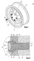
- Reference numeral 1 is a rim for a car, which in their middle part in the usual way with several circular openings or holes is provided, of which only one of the holes with the Reference numeral 2 has been provided.
- Fig. 1 From Fig. 1 it can be seen that the rim 1 in this area on an imaginary Circle with constant angular intervals over the circumference of the circle to each other arranged a total of five such holes 2 or the like.
- each wheel bolt 3 consists essentially of a head 4 and a bolt-shaped shaft 5, which consists of two longitudinal sections different diameter D or d exists (Fig. 3).
- the stem length part T With the smaller diameter d, the is threadless.
- Material in one piece to the shaft longitudinal part T closes provided with screw thread 6 length section with the larger diameter D on.
- the letter L denotes the overall length of the wheel bolt 3 and the letters K or V further longitudinal sections of the wheel bolt 3, wherein the longitudinal section K essentially marks the total length of the head 4 and V the shaft length.
- the head 4 has an inner recess 7, which is used to attack a tool, in particular a key is formed.
- the inner recess 7 with a suitable shape, for example with a polygon or polygon 8, into which a key (not shown) fits engages to the wheel bolt 3 about its longitudinal axis 9 in one or the other To turn direction, so either tighten or unscrew.
- the head 4 of the wheel bolt 3 has on its outside in its middle Length section of an approximately cylindrical design, leading to its outer end rounded to a radius R and in a planar, orthogonal to the Longitudinal axis 9 directed end face 10 opens.
- This conical or conical outer surface of the head 4 is additionally denoted by the reference numeral eleventh designated.
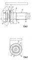
- the diameter of the head 4 carries the letter P (FIG. 4). Of the Diameter of the head P is matched to the outer extended part 12th (Fig. 2) of the bore 2 of the wheel rim 1, so that the head 4 at least partially with its axial length is arranged in this outer part 12 of the bore 2 (Fig. 1.2).
- a ring body 13 On the unthreaded shaft longitudinal part T is in the wheel bolt assembly according to the invention arranged a ring body 13, in detail from the Fig. 6 and 7 can be seen.
- This annular body 13 has a central recess or bore 14, which consist of different lengths (FIG. 7) consists.
- the ring body 13 has the length G (FIG. 7). With H is a middle one axial length portion, parallel to the longitudinal axis 15 of the ring body 13 denotes.
- the total axial length G is less than the axial length of the threadless Shaft longitudinal part T, for example, only half of this shaft longitudinal part T or z. B. amount to one third of it.
- the outer diameter F (FIG. 6) of the Ring body 13 is slightly larger in the embodiment shown in FIG. 3 embodiment dimensioned as the diameter P of the head 4 of the wheel bolt 3, but can also in case of need the same diameter as the head 4 or z. Belly be slightly smaller than this (not shown).
- the smallest diameter C (FIG. 6) of the central recess 14 is something greater than the diameter of the screwless shaft longitudinal part T, so that the Ring body 13 is arranged with a certain play on the shaft longitudinal part T.
- the diameter C of the central recess 14 will be dimensioned that the annular body 13 also provided via the threaded 6 Sliding shaft longitudinal part of the wheel bolt 3 and in the apparent from FIGS. 2 and 3 Can bring situation in which the ring body 13 directly to the kegligen or conical lateral surface 11 of the head 4 is applied, so in this position between the bottom of the head 4 and the threaded 6 provided Shaft longitudinal part of the wheel bolt 3 is located (Fig. 2).
- the ring body 13 on its head 4 facing side formed conically under the opening angle ⁇ (FIG. 7) on a certain axial part, such that also in this area a conical or conical Ring inner lateral surface 16 (Fig. 7) results, with which the annular body 13, preferably positive fit, against the conical or conical lateral surface 11 of the head 4 of the wheel bolt 3 with the opening angle ⁇ largely positive fit applies, whereby it has it by appropriate tolerances in the hand, the arrangement to choose so that the contact between the head 4 and its lateral surface 11 and the conical or conical annular inner surface 16 of the annular body 13 preferably takes place at the outer diameter, but not exclusively applies.
- the annular body 13 is on its outer circumferential surface also formed substantially in two parts.
- spherical Approximately in the central axial length H of the annular body 13 is spherical, present shaped according to a radius Y, so that here is a spherical or spherical outer surface 17 results, with the annular body 13 in the corresponding shape designed outer part 12 of the bore 2 rests positively.
- the arrangement is preferably made so that the contact between ring body 13 and rim 1 in the center of the spherical surface 17 is present.
- the contact between the wheel bolt 3 and ring body 13 at the outer Diameter takes place and the contact between ring body 13 and rim 1 in the center of this spherical part is present, resulting in a plate spring elastic Effect, with the resilient restoring force of the ring body 13 already mentioned above Dissolution behavior positively supported in the sense of non-dissolution.
- the ring body z. B. made of spring steel, while the rim z. B. from a Aluminum alloy and the wheel bolt 3 in turn made of a steel alloy, in particular of hardened steel.
- edge portions of the ring body 13 are the same as the corresponding ones Transition areas on the head 4 of the wheel bolt 3 for corresponding radii rounded, which are not particularly marked in the drawing.
- the angle ⁇ and ⁇ can be the same size and z. B. each 120 degrees, with appropriate tolerances, while at a Example of the threadless shank length part T 13 mm and in this direction measured axial length of the ring body 13 is seven to about eight millimeters.
- the radius Y of the crown can be, for example, 13 mm, while the Angle ⁇ (Fig. 7) is, for example, 60 degrees (Fig. 7).
- a and B are different large diameter on the ring body 13.
- the ring body 13 can be lost on the shaft 5 may be arranged.
- E is a longitudinal portion of the ring body 13.
Landscapes
- Engineering & Computer Science (AREA)
- General Engineering & Computer Science (AREA)
- Mechanical Engineering (AREA)
- Connection Of Plates (AREA)
Abstract
Description
- Fig. 1
- eine Radfelge für einen PKW mit Radschrauben, in perspektivischer Darstellung;
- Fig. 2
- einen Längsschnitt, teils abgebrochen dargestellt, durch eine erfindungsgemäße Radschraubenanordnung;
- Fig. 3
- eine erfindungsgemäße Radschraube mit Ringkörper in der Ansicht;
- Fig. 4
- eine Stirnansicht auf den Kopf der Radschraube gemäß Fig. 3;
- Fig. 5
- die aus den Fig. 3 und 4 ersichtliche Radschraube in perspektivischer Darstellung;
- Fig. 6
- einen Ringkörper in der Ansicht und
- Fig. 7
- einen Axiallängsschnitt zu Fig. 6.
- 1
- Felge, Radfelge
- 2
- Bohrung
- 3
- Radschraube
- 4
- Kopf
- 5
- Schaft, bolzenförmiger
- 6
- Schraubgewinde
- 7
- Innenaussparung
- 8
- Mehreck, Vieleck
- 9
- Längsachse der Radschraube 3
- 10
- Stirnfläche der Radschraube 3
- 11
- Mantelfläche, Oberfläche
- 12
- Teil, äußerer, Ausnehmung
- 13
- Ringkörper
- 14
- Ausnehmung, zentrische, Bohrung
- 15
- Längsachse des Ringkörpers 13
- 16
- Innenfläche, Ringinnenfläche, Oberfläche
- 17
- Außenmantelfläche, Oberfläche
- A
- Durchmesser der Ausnehmung 14
- B
- " " "
- C
- Durchmesser, kleinster
- d
- Durchmesser, gewindeloser, am Schaft 5
- D
- " , mit Gewinde versehener, am Schaft 5
- E
- Längenabschnitt am Ringkörper 13
- F
- Außendurchmesser des Ringkörpers 13
- G
- Axiale Länge des Ringskörpers 13
- H
- Längenabschnitt, mittlerer, axialer
- K
- Axiale Länge des Kopfes 4
- L
- Gesamtlänge der Radschraube 3
- M
- Durchmesser am Ringkörper 13
- P
- Durchmesses des Kopfes 4
- R
- Radius am Kopf 4
- T
- Schaftlängenteil ohne Gewinde
- V
- Schaftlänge
- Y
- Radius an Außenmantelfläche des Ringkörpers 13
- α
- Öffnungswinkel (Kegelwinkel) am Kopf 4, Konuswinkel
- β
- Öffnungswinkel einer Öffnung am Ringkörper 13 (Kopf zugekehrte Seite), Konuswinkel
- γ
- Öffnungswinkel eines Teils der zentrischen Ausnehmung am Ringkörper 13, Konuswinkel
- δ
- Kegel-/Konuswinkel
Claims (21)
- Radschraubenanordnung für PKW oder sonstige Fahrzeuge, mit einer Radschraube (3), die mit ihrem freien Endabschnitt des mit Schraubgewinde (6) versehenen bolzenförmigen Schaftes (5) in eine Bohrung (2) oder Ausnehmung (12) einer Radfelge (1) eingreift und in ein Mitnehmerteil eingeschraubt ist, wobei zwischen einem mit dem Schaft (5) materialmäßig einstückig verbundenen Kopf (4) mit geeigneter Innen- oder Außenprofilierung für einen Werkzeugangriff und der Felge (1) ein Ringkörper (13) angeordnet ist, der eine zentrische Ausnehmung (14) aufweist, die von dem Schaft (5) der Radschraube (3) durchgriffen ist, wobei der Kopf (4) der Radschraube (3) an seiner dem Ringkörper (13) zugekehrten inneren (unteren) Mantelfläche mit einer von einer zylindrischen Formgestaltung abweichenden Mantelfläche (11) versehen ist, gegen die der Ringkörper (13) mit einer entsprechend gestalteten Ringinnenmantelfläche (16) weitgehend formschlüssig anliegt, und dass der Ringkörper (13) auch an seiner der Bohrung (2) oder Ausnehmung (12) der Felge (1) zugekehrten Außenmantelfläche (17) mit einer von einem Zylinder abweichenden Formgestaltung an einer formmäßig entsprechenden Gegenfläche der Ausnehmung (12) oder Bohrung (2) weitgehend formschlüssig anliegt.
- Radschraubenanordnung für PKW oder sonstige Fahrzeuge, mit einer Radschraube (3), die mit ihrem freien Endabschnitt des mit Schraubgewinde (6) versehenen bolzenförmigen Schaftes (5) in eine Bohrung (2) oder Ausnehmung (12) einer Radfelge (1) eingreift und in ein Mitnehmerteil eingeschraubt ist, wobei zwischen einem mit dem Schaft (5) materialmäßig einstückig verbundenen Kopf (4) mit geeigneter Innen- oder Außenprofilierung für einen Werkzeugangriff und der Felge (1) ein Ringkörper (13) angeordnet ist, der eine zentrische Ausnehmung (14) aufweist, die von dem Schaft (5) der Radschraube (3) durchgriffen ist, wobei der Kopf (4) der Radschraube (3) an seiner dem Ringkörper (13) zugekehrten inneren (unteren) Mantelfläche mit einer von einer zylindrischen Formgestaltung abweichenden Mantelfläche (11) versehen ist, gegen die der Ringkörper (13) mit einer entsprechend gestalteten Ringinnenmantelfläche (16) weitgehend formschlüssig anliegt und dass der Ringkörper (13) auch an seiner der Bohrung (2) oder Ausnehmung (12) der Felge (1) zugekehrten Außenmantelfläche mit einer von einem Zylinder abweichenden Formgestaltung an einer formmäßig entsprechenden Gegenfläche der Ausnehmung (12) oder Bohrung (2) weitgehend formschlüssig anliegt, derart, dass die einander zugekehrten Mantelflächenbereiche (11) des Kopfes (4) der Radschraube (3) und der zugeordneten Ringinnenmantelfläche (16) in bezug auf die Längsachse (9) der Radschraube (3) konisch bzw. kegelig nach der Kopfaußenseite erweitert ausgebildet sind, und dass auch die einander zugekehrten und miteinander zusammenwirkenden Oberflächenbereiche vom Ringkörper (13) und Bohrung (2) bzw. Ausnehmung (12) der Felge (1) entsprechend konisch bzw. kegelig ausgebildet sind.
- Radschraubenanordnung für PKW oder sonstige Fahrzeuge, mit einer Radschraube (3), die mit ihrem freien Endabschnitt des mit Schraubgewinde (6) versehenen bolzenförmigen Schaftes (5) in eine Bohrung (2) oder Ausnehmung (12) einer Radfelge (1) eingreift und in ein Mitnehmerteil eingeschraubt ist, wobei zwischen einem mit dem Schaft (5) materialmäßig einstückig verbundenen Kopf (4) mit geeigneter Innen- oder Außenprofilierung für einen Werkzeugangriff und der Felge (1) ein Ringkörper (13) angeordnet ist, der eine zentrische Ausnehmung (14) aufweist, die von dem Schaft (5) der Radschraube (3) durchgriffen ist, wobei der Kopf (4) der Radschraube (3) an seiner dem Ringkörper (13) zugekehrten inneren (unteren) Mantelfläche mit einer von einer zylindrischen Formgestaltung abweichenden Mantelfläche (11) versehen ist, gegen die der Ringkörper (13) mit einer entsprechend gestalteten Ringinnenmantelfläche (16) weitgehend formschlüssig anliegt und dass der Ringkörper (13) auch an seiner der Bohrung (2) oder Ausnehmung (12) der Felge (1) zugekehrten Außenmantelfläche mit einer von einem Zylinder abweichenden Formgestaltung an einer entsprechenden Gegenfläche der Ausnehmung (12) oder Bohrung (2) weitgehend formschlüssig anliegt, wobei die einander zugekehrten Mantelflächenbereiche (11) des Kopfes (4) der Radschraube (3) und der zugeordneten Ringinnenmantelfläche (16) des Ringkörpers (13) in bezug auf die Längsachse (9) der Radschraube (3) zum Kopf (4) der Radschraube (3) konisch bzw. kegelig erweitert ausgebildet sind, während die einander zugekehrten und miteinander zusammenwirkenden Oberflächenbereiche vom Ringkörper (13) und Bohrung (2) bzw. Ausnehmung (12) der Felge (1) jeweils als Oberflächenbereiche je einer Kugel ausgebildet sind.
- Radschraubenanordnung für PKW oder sonstige Fahrzeuge, mit einer Radschraube (3), die mit ihrem freien Endabschnitt des mit Schraubgewinde (6) versehenen bolzenförmigen Schaftes (5) in eine Bohrung (2) oder Ausnehmung (12) einer Radfelge (1) eingreift und in ein Mitnehmerteil eingeschraubt ist, wobei zwischen einem mit dem Schaft (5) materialmäßig einstückig verbundenen Kopf (4) mit geeigneter Innen- oder Außenprofilierung für einen Werkzeugangriff und der Felge (1) ein Ringkörper (13) angeordnet ist, der eine zentrische Ausnehmung (14) aufweist, die von dem Schaft (5) der Radschraube (3) durchgriffen ist, wobei der Kopf (4) der Radschraube (3) an seiner dem Ringkörper (13) zugekehrten inneren (unteren) Mantelfläche mit einer von einer zylindrischen Formgestaltung abweichenden Mantelfläche (11) versehen ist, gegen die der Ringkörper (13) mit einer entsprechend gestalteten Ringinnenmantelfläche (16) weitgehend formschlüssig anliegt und dass der Ringkörper (13) auch an seiner der Bohrung (2) oder Ausnehmung (12) der Felge (1) zugekehrten Außenmantelfläche mit einer von einem Zylinder abweichenden Formgestaltung an einer entsprechenden Gegenfläche der Ausnehmung (12) oder Bohrung (2) weitgehend formschlüssig anliegt, wobei die einander zugekehrten Mantelflächenbereiche (11) des Kopfes (4) der Radschraube (3) und der zugeordneten Ringinnenmantelfläche (16) des Ringkörpers (13) in bezug auf die Längsachse (9) der Radschraube (3) zum Kopf (4) der Radschraube (3) konisch bzw. kegelig erweitert ausgebildet sind, während die einander zugekehrten und miteinander zusammenwirkenden Oberflächenbereiche vom Ringkörper (13) und Bohrung (2) bzw. Ausnehmung (12) der Felge (1) jeweils nach einer von einem Kreisradius abweichenden Kurve verlaufend ausgebildet sind.
- Radschraubenanordnung für PKW oder sonstige Fahrzeuge, mit einer Radschraube (3), die mit ihrem freien Endabschnitt des mit Schraubgewinde (6) versehenen bolzenförmigen Schaftes (5) in eine Bohrung (2) oder Ausnehmung (12) einer Radfelge (1) eingreift und in ein Mitnehmerteil eingeschraubt ist, wobei zwischen einem mit dem Schaft (5) materialmäßig einstückig verbundenen Kopf (4) mit geeigneter Innen- oder Außenprofilierung für einen Werkzeugangriff und der Felge (1) ein Ringkörper (13) angeordnet ist, der eine zentrische Ausnehmung (14) aufweist, die von dem Schaft (5) der Radschraube (3) durchgriffen ist, wobei der Kopf (4) der Radschraube (3) an seiner dem Ringkörper (13) zugekehrten inneren (unteren) Mantelfläche mit einer von einer zylindrischen Formgestaltung abweichenden Mantelfläche (11) versehen ist, gegen die der Ringkörper (13) mit einer entsprechend gestalteten Ringinnenmantelfläche (16) weitgehend formschlüssig anliegt und dass der Ringkörper (13) auch seiner der Bohrung (2) oder Ausnehmung (12) der Felge (1) zugekehrten Außenmantelfläche mit einer von einem Zylinder abweichenden Formgestaltung an einer entsprechenden Gegenfläche der Ausnehmung (12) oder Bohrung (2) weitgehend formschlüssig anliegt, wobei die einander zugekehrten Mantelflächenbereiche (11) des Kopfes (4) der Radschraube (3) und der zugeordneten Ringinnenmantelfläche (16) des Ringkörpers (13) als Oberflächenbereiche in je einer Kugel ausgebildet sind, während die einander zugekehrten und miteinander zusammenwirkenden Oberflächenbereiche von Ringkörper (13) und Bohrung (2) bzw. Ausnehmung (12) der Felge (1) ebenfalls als Oberflächenbereiche je einer Kugel, oder konisch bzw. kegelig oder jeweils nach von einem Kreisradius abweichenden Kurve ausgebildet sind.
- Radschraubenanordnung für PKW oder sonstige Fahrzeuge, mit einer Radschraube (3), die mit ihrem freien Endabschnitt des mit Schraubgewinde (6) versehenen bolzenförmigen Schaftes (5) in eine Bohrung (2) oder Ausnehmung (12) einer Radfelge (1) eingreift und in ein Mitnehmerteil eingeschraubt ist, wobei zwischen einem mit dem Schaft (5) materialmäßig einstückig verbundenen Kopf (4) mit geeigneter Innen- oder Außenprofilierung für einen Werkzeugangriff und der Felge (1) ein Ringkörper (13) angeordnet ist, der eine zentrische Ausnehmung (14) aufweist, die von dem Schaft (5) der Radschraube (3) durchgriffen ist, wobei der Kopf (4) der Radschraube (3) an seiner dem Ringkörper (13) zugekehrten inneren (unteren) Mantelfläche mit einer von einer zylindrischen Formgestaltung abweichenden Mantelfläche (11) versehen ist, gegen die der Ringkörper (13) mit einer entsprechend gestalteten Ringinnenmantelfläche (16) weitgehend formschlüssig anliegt und dass der Ringkörper (13) auch an seiner der Bohrung (2) oder Ausnehmung (12) der Felge (1) zugekehrten Außenmantelfläche mit einer von einem Zylinder abweichenden Formgestaltung an einer entsprechenden Gegenfläche der Ausnehmung (12) oder Bohrung (2) weitgehend formschlüssig anliegt, wobei die einander zugekehrten Mantelflächen (11) des Kopfes (4) der Radschraube (3) und der zugeordneten Ringinnenmantelfläche (16) des Ringkörpers (13) jeweils nach einer von einem Kreisradius abweichenden Kurve verlaufend ausgebildet sind, während die einander zugekehrten und miteinander zusammenwirkenden Oberflächenbereiche von Ringkörper (13) und Bohrung (2) bzw. Ausnehmung (12) der Felge (1) in bezug auf die Längsachse (9) der Radschraube (3) zum Kopf (4) der Radschraube (3) konisch bzw. kegelig erweitert ausgebildet sind, oder die miteinander zusammenwirkenden Oberflächenbereiche vom Ringkörper (13) und Bohrung (2) bzw. Ausnehmung (12) der Felge (1) jeweils nach einer von einem Kreisradius abweichenden Kurve oder jeweils als Oberflächenbereiche von Kugeln ausgebildet sind.
- Radschraubenanordnung für PKW oder sonstige Fahrzeuge, mit einer Radschraube (3), die mit ihrem freien Endabschnitt des mit Schraubgewinde (6) versehenen bolzenförmigen Schaftes (5) in eine Bohrung (2) oder Ausnehmung (12) einer Radfelge (1) eingreift und in ein Mitnehmerteil eingeschraubt ist, wobei zwischen einem mit dem Schaft (5) materialmäßig einstückig verbundenen Kopf (4) mit geeigneter Innen- oder Außenprofilierung für einen Werkzeugangriff und der Felge (1) ein Ringkörper (13) angeordnet ist, der eine zentrische Ausnehmung (14) aufweist, die von dem Schaft (5) der Radschraube (3) durchgriffen ist, wobei der Kopf (4) der Radschraube (3) an seiner dem Ringkörper (13) zugekehrten inneren (unteren) Mantelfläche mit einer von einer zylindrischen Formgestaltung abweichenden Mantelfläche (11) versehen ist, gegen die der Ringkörper (13) mit einer entsprechend gestalteten Ringinnenmantelfläche (16) weitgehend formschlüssig anliegt und das der Ringkörper (13) auch an seiner der Bohrung (2) oder Aussparung (12) der Felge (1) zugekehrten Mantelfläche nach einer von der zylindrischen Formgestaltung abweichenden Kurve ausgebildet ist, und zwar derart, dass sowohl die miteinander zusammenwirkenden Oberflächen (11, 16) des Kopfes (4) und des Ringkörpers (13), als auch die miteinander zusammenwirkenden Oberflächen (17) des Ringkörpers (13) und der Bohrung (2) bzw. des äußeren Teils der Bohrung (2) bzw. deren Ausnehmung (12) je nach den vorliegenden Kraftverhältnissen nach Kurven gestaltet sind, die einerseits eine gute zentrische Lage der Radschraube (3) in bezug auf die Bohrung (2) der Felge (1) und andererseits ein möglichst optimales Federverhalten des Ringkörpers (13) gewährleisten.
- Radschraubenanordnung nach Anspruch 1 oder einem der darauffolgenden Ansprüche, dadurch gekennzeichnet, dass der Körperkontakt zwischen der Unterseite des Kopfes (4) der Radschraube (3) und des Ringkörpers (13) am äußeren, dem Kopf zugekehrten Durchmesser und der Kontakt zwischen Ringkörper (13) und der Felge (1) etwa in der Mitte des Ringkörpers (13) erfolgt.
- Radschraubenanordnung nach Anspruch 1 oder einem der darauffolgenden Ansprüche, dadurch gekennzeichnet, dass die axiale Länge (G) (Dicke) des Ringkörpers (13) so bemessen ist, dass die Elastizität der Radschraube (3) um mindestens 35 % erhöht ist.
- Radschraubenanordnung nach Anspruch 1 oder einem der darauffolgenden Ansprüche, dadurch gekennzeichnet, dass eine Innenaussparung (7) für einen Werkzeugangriff am Kopf (4) als Mehrkant ausgebildet ist.
- Radschraubenanordnung nach Anspruch 1 oder einem der Ansprüche 2 bis 9, dadurch gekennzeichnet, dass der Kopf (4) der Radschraube (3) mit einem Außenmehrkant für einen Werkzeugangriff versehen ist.
- Radschraubenanordnung nach Anspruch 1 oder einem der darauffolgenden Ansprüche, dadurch gekennzeichnet, dass der Ringkörper (13) aus einem anderem Werkstoff als die Radschraube (3) besteht.
- Radschraubenanordnung nach Anspruch 1 oder einem der darauffolgenden Ansprüche, dadurch gekennzeichnet, dass der Ringkörper (13) auf dem Schaft (5) der Radschraube (3) unverlierbar angeordnet ist.
- Radschraubenanordnung nach Anspruch 1 oder einem der darauffolgenden Ansprüche, dadurch gekennzeichnet, dass bei Ausbildung der miteinander zusammenwirkenden Oberflächenbereiche zwischen dem Kopf (4) und dem Ringkörper (13) einerseits sowie zwischen dem Ringkörper (13) einerseits und der Bohrung (2) bzw. Ausnehmung (12) andererseits als Oberflächenbereiche von Kugeln oder als Oberflächenbereiche, die durch Kurven gebildet werden, die von einer Kreisform abweichen, in dem mittleren Bereich der jeweiligen Auflageflächen auf diametral gegenüberliegenden Seiten angelegte Tangente einen mittleren Tangentialkegel miteinander bilden, der jeweils einen Winkel von über 90 Grad einschließt, wobei dieser mittlere Tangentialkegelwinkel zwischen Ringkörper (13) und Felge (1) kleiner ist als der mittlere Tangentialwinkel zwischen Kopf (4) und Ringkörper (13).
- Radschraubenanordnung nach Anspruch 1 oder einem der darauffolgenden Ansprüche, dadurch gekennzeichnet, dass der Konuswinkel (α) der mit dem Ringkörper (13) zusammenwirkenden Mantelfläche (11) des Kopfes (4) stumpfwinklig ausgebildet ist und dass der Scheitel des Winkels (α) auf der Längsachse (9) der Radschraube (3) liegt.
- Radschraubenanordnung nach Anspruch 1 oder einem der darauffolgenden Ansprüche, dadurch gekennzeichnet, dass die Kegelwinkel (α) der miteinander zusammenwirkenden Mantelflächenbereiche (11, 16) des Kopfes (4) der Radschraube (3) und des Ringkörpers (13) stumpfwinklig sind und zum Kopf (4) hin geöffnet verlaufen.
- Radschraubenanordnung nach Anspruch 1 oder einem der darauffolgenden Ansprüche, dadurch gekennzeichnet, dass die Konuswinkel der miteinander zusammenwirkenden Oberflächenbereiche (11, 16) von Kopf (4) und Ringkörper (13) - unter Einhaltung unterschiedlicher Toleranzen für den Kopf (4) und für den Ringkörper (13) - jeweils 120 Grad beträgt.
- Radschraubenanordnung nach Anspruch 1 oder einem der darauffolgenden Ansprüche, dadurch gekennzeichnet, dass der Ringkörper (13) aus Stahl, Aluminium oder aus Titan oder aus Federstahl besteht, während die Radschraube (3) aus gehärtetem Stahl hergestellt ist.
- Radschraubenanordnung nach Anspruch 1 oder einem der darauffolgenden Ansprüche, dadurch gekennzeichnet, dass auf diametral einander gegenüberliegenden Seiten an die Außenmantelfläche (17) des Ringkörpers (13) angelegte Tangenten einen Konus- bzw. Kegelwinkel (δ) einschließen, der kleiner ist als der Öffnungswinkel (Kegelwinkel - α) am Kopf (4).
- Radschraubenanordnung nach Anspruch 19, dadurch gekennzeichnet, dass der Winkel (δ) 60 Grad, oder 70 Grad oder 90 Grad, vorzugsweise aber kleiner als 120 Grad, bemessen ist.
- Radschraubenanordnung nach Anspruch 19 oder 20, dadurch gekennzeichnet, dass der Scheitel des Winkels (δ) auf der Längsachse (15) des Ringkörpers (13) angeordnet ist.
Applications Claiming Priority (2)
| Application Number | Priority Date | Filing Date | Title |
|---|---|---|---|
| DE20317196U | 2003-11-05 | ||
| DE20317196U DE20317196U1 (de) | 2003-11-05 | 2003-11-05 | Radschraubenanordnung für PKW oder sonstige Fahrzeuge |
Publications (3)
| Publication Number | Publication Date |
|---|---|
| EP1529969A2 true EP1529969A2 (de) | 2005-05-11 |
| EP1529969A3 EP1529969A3 (de) | 2006-05-10 |
| EP1529969B1 EP1529969B1 (de) | 2008-11-05 |
Family
ID=30470145
Family Applications (1)
| Application Number | Title | Priority Date | Filing Date |
|---|---|---|---|
| EP04019001A Revoked EP1529969B1 (de) | 2003-11-05 | 2004-08-11 | Gegen Lösen gesicherte Radschraubenanordnung für PKW oder sonstige Fahrzeug |
Country Status (3)
| Country | Link |
|---|---|
| EP (1) | EP1529969B1 (de) |
| AT (1) | ATE413537T1 (de) |
| DE (2) | DE20317196U1 (de) |
Families Citing this family (4)
| Publication number | Priority date | Publication date | Assignee | Title |
|---|---|---|---|---|
| DE102013221514B4 (de) | 2013-10-23 | 2025-10-02 | Bayerische Motoren Werke Aktiengesellschaft | Befestigungsanordnung eines aus kohlefaserverstärktem Kunststoff bestehenden Fahrzeug-Rades |
| US10935058B2 (en) | 2014-08-01 | 2021-03-02 | Hpt Sinergy S.R.L. | Device for fixing a blank to a modular support system |
| EP3600913B2 (de) | 2017-03-29 | 2024-11-13 | Mubea Carbo Tech GmbH | Rad für fahrzeug |
| FR3119342B1 (fr) | 2021-02-02 | 2022-12-16 | Psa Automobiles Sa | Organe de fixation d'une roue en application axiale contre le moyeu d'un essieu de vehicule automobile |
Family Cites Families (6)
| Publication number | Priority date | Publication date | Assignee | Title |
|---|---|---|---|---|
| FR2210515B1 (de) * | 1972-12-20 | 1976-06-04 | Amil | |
| FR2474119A1 (fr) * | 1980-01-18 | 1981-07-24 | Peugeot | Dispositif de fixation, notamment pour roue de vehicule |
| DE19832513A1 (de) * | 1998-07-20 | 2000-02-17 | Impag Gmbh Medizintechnik | Befestigungsanordnung |
| DE19942836C2 (de) * | 1999-09-08 | 2003-04-17 | Porsche Ag | Scheibenelement für eine Radschraube bzw. Radmutter eines Kraftfahrzeuges |
| IT1319898B1 (it) * | 2000-02-10 | 2003-11-12 | I B S Ind Bulloneria Speciale | Dispositivo di fissaggio, in particolare per ruota di autoveicolo. |
| SE521090C2 (sv) * | 2001-03-21 | 2003-09-30 | Volvo Lastvagnar Ab | Anordning vid skruvförband |
-
2003
- 2003-11-05 DE DE20317196U patent/DE20317196U1/de not_active Expired - Lifetime
-
2004
- 2004-08-11 EP EP04019001A patent/EP1529969B1/de not_active Revoked
- 2004-08-11 AT AT04019001T patent/ATE413537T1/de not_active IP Right Cessation
- 2004-08-11 DE DE502004008394T patent/DE502004008394D1/de not_active Revoked
Also Published As
| Publication number | Publication date |
|---|---|
| EP1529969B1 (de) | 2008-11-05 |
| DE20317196U1 (de) | 2004-01-15 |
| ATE413537T1 (de) | 2008-11-15 |
| EP1529969A3 (de) | 2006-05-10 |
| DE502004008394D1 (de) | 2008-12-18 |
Similar Documents
| Publication | Publication Date | Title |
|---|---|---|
| EP2822888B1 (de) | Ringschraube | |
| DE20012107U1 (de) | Verbindungselement | |
| DE102009042720A1 (de) | Gleitschutzstift | |
| DE102014116227A1 (de) | Sicherungselement und Sicherungssystem | |
| EP1809489B1 (de) | Radnaben-gelenk-einheit | |
| EP2812199B1 (de) | Luftfederbefestigung | |
| EP3153725B1 (de) | Verfahren und vorrichtung zur befestigung eines kunststoffbauteils an einem tragenden bauteil | |
| DE10262070B4 (de) | Zusammengesetzte Bremsscheibe | |
| DE69401636T2 (de) | Radnabeeinrichtung mit Lagervorrichtung und homokinetischer Kupplung | |
| DE102004029877A1 (de) | Gebauter Kolben für einen Verbrennungsmotor | |
| DE102011081935A1 (de) | Kugelgelenk | |
| DE102018222261B4 (de) | Radanordnung | |
| EP1529969B1 (de) | Gegen Lösen gesicherte Radschraubenanordnung für PKW oder sonstige Fahrzeug | |
| EP3705740B1 (de) | Schraubverbindung und verfahren zur losdrehsicherung der schraubverbindung | |
| DE19748117C2 (de) | Kugelzapfen | |
| DE102017128522A1 (de) | Kugelgewindetrieb | |
| DE69514215T2 (de) | Spielfreie Zugstangenanordnung für einen Güterwagon | |
| EP1600590B1 (de) | Anschlagpuffer | |
| EP3831258B1 (de) | Scharnier zur lagerung einer toilettenauflage | |
| EP3323629B1 (de) | Radlageranordnung | |
| DE69901267T2 (de) | Sicherheitsverriegelung für ein Rad | |
| DE202019100823U1 (de) | Wirbelringschraube | |
| DE102012112362C5 (de) | Ventil mit einer Befestigungseinrichtung | |
| DE102018129285A1 (de) | Radlager für ein Kraftfahrzeug | |
| DE202004012253U1 (de) | Befestigungsanordnung |
Legal Events
| Date | Code | Title | Description |
|---|---|---|---|
| PUAI | Public reference made under article 153(3) epc to a published international application that has entered the european phase |
Free format text: ORIGINAL CODE: 0009012 |
|
| AK | Designated contracting states |
Kind code of ref document: A2 Designated state(s): AT BE BG CH CY CZ DE DK EE ES FI FR GB GR HU IE IT LI LU MC NL PL PT RO SE SI SK TR |
|
| AX | Request for extension of the european patent |
Extension state: AL HR LT LV MK |
|
| 17P | Request for examination filed |
Effective date: 20050818 |
|
| PUAL | Search report despatched |
Free format text: ORIGINAL CODE: 0009013 |
|
| RIC1 | Information provided on ipc code assigned before grant |
Ipc: F16B 43/02 20060101ALI20060309BHEP Ipc: B60B 3/16 20060101ALI20060309BHEP Ipc: F16B 39/24 20060101AFI20050216BHEP |
|
| AK | Designated contracting states |
Kind code of ref document: A3 Designated state(s): AT BE BG CH CY CZ DE DK EE ES FI FR GB GR HU IE IT LI LU MC NL PL PT RO SE SI SK TR |
|
| AX | Request for extension of the european patent |
Extension state: AL HR LT LV MK |
|
| AKX | Designation fees paid |
Designated state(s): AT BE BG CH CY CZ DE DK EE ES FI FR GB GR HU IE IT LI LU MC NL PL PT RO SE SI SK TR |
|
| 17Q | First examination report despatched |
Effective date: 20070920 |
|
| GRAP | Despatch of communication of intention to grant a patent |
Free format text: ORIGINAL CODE: EPIDOSNIGR1 |
|
| GRAS | Grant fee paid |
Free format text: ORIGINAL CODE: EPIDOSNIGR3 |
|
| GRAA | (expected) grant |
Free format text: ORIGINAL CODE: 0009210 |
|
| AK | Designated contracting states |
Kind code of ref document: B1 Designated state(s): AT BE BG CH CY CZ DE DK EE ES FI FR GB GR HU IE IT LI LU MC NL PL PT RO SE SI SK TR |
|
| REG | Reference to a national code |
Ref country code: GB Ref legal event code: FG4D Free format text: NOT ENGLISH |
|
| REG | Reference to a national code |
Ref country code: CH Ref legal event code: EP |
|
| REG | Reference to a national code |
Ref country code: IE Ref legal event code: FG4D Free format text: LANGUAGE OF EP DOCUMENT: GERMAN |
|
| REF | Corresponds to: |
Ref document number: 502004008394 Country of ref document: DE Date of ref document: 20081218 Kind code of ref document: P |
|
| NLV1 | Nl: lapsed or annulled due to failure to fulfill the requirements of art. 29p and 29m of the patents act | ||
| PG25 | Lapsed in a contracting state [announced via postgrant information from national office to epo] |
Ref country code: ES Free format text: LAPSE BECAUSE OF FAILURE TO SUBMIT A TRANSLATION OF THE DESCRIPTION OR TO PAY THE FEE WITHIN THE PRESCRIBED TIME-LIMIT Effective date: 20090216 |
|
| PG25 | Lapsed in a contracting state [announced via postgrant information from national office to epo] |
Ref country code: PL Free format text: LAPSE BECAUSE OF FAILURE TO SUBMIT A TRANSLATION OF THE DESCRIPTION OR TO PAY THE FEE WITHIN THE PRESCRIBED TIME-LIMIT Effective date: 20081105 Ref country code: FI Free format text: LAPSE BECAUSE OF FAILURE TO SUBMIT A TRANSLATION OF THE DESCRIPTION OR TO PAY THE FEE WITHIN THE PRESCRIBED TIME-LIMIT Effective date: 20081105 Ref country code: SI Free format text: LAPSE BECAUSE OF FAILURE TO SUBMIT A TRANSLATION OF THE DESCRIPTION OR TO PAY THE FEE WITHIN THE PRESCRIBED TIME-LIMIT Effective date: 20081105 Ref country code: NL Free format text: LAPSE BECAUSE OF FAILURE TO SUBMIT A TRANSLATION OF THE DESCRIPTION OR TO PAY THE FEE WITHIN THE PRESCRIBED TIME-LIMIT Effective date: 20081105 |
|
| PLBI | Opposition filed |
Free format text: ORIGINAL CODE: 0009260 |
|
| 26 | Opposition filed |
Opponent name: KAMAX-WERKE RUDOLF KELLERMANN GMBH & CO. KG Effective date: 20090603 |
|
| REG | Reference to a national code |
Ref country code: IE Ref legal event code: FD4D |
|
| PG25 | Lapsed in a contracting state [announced via postgrant information from national office to epo] |
Ref country code: BG Free format text: LAPSE BECAUSE OF FAILURE TO SUBMIT A TRANSLATION OF THE DESCRIPTION OR TO PAY THE FEE WITHIN THE PRESCRIBED TIME-LIMIT Effective date: 20090205 Ref country code: DK Free format text: LAPSE BECAUSE OF FAILURE TO SUBMIT A TRANSLATION OF THE DESCRIPTION OR TO PAY THE FEE WITHIN THE PRESCRIBED TIME-LIMIT Effective date: 20081105 Ref country code: IE Free format text: LAPSE BECAUSE OF FAILURE TO SUBMIT A TRANSLATION OF THE DESCRIPTION OR TO PAY THE FEE WITHIN THE PRESCRIBED TIME-LIMIT Effective date: 20081105 Ref country code: EE Free format text: LAPSE BECAUSE OF FAILURE TO SUBMIT A TRANSLATION OF THE DESCRIPTION OR TO PAY THE FEE WITHIN THE PRESCRIBED TIME-LIMIT Effective date: 20081105 Ref country code: RO Free format text: LAPSE BECAUSE OF FAILURE TO SUBMIT A TRANSLATION OF THE DESCRIPTION OR TO PAY THE FEE WITHIN THE PRESCRIBED TIME-LIMIT Effective date: 20081105 |
|
| PG25 | Lapsed in a contracting state [announced via postgrant information from national office to epo] |
Ref country code: CZ Free format text: LAPSE BECAUSE OF FAILURE TO SUBMIT A TRANSLATION OF THE DESCRIPTION OR TO PAY THE FEE WITHIN THE PRESCRIBED TIME-LIMIT Effective date: 20081105 Ref country code: SE Free format text: LAPSE BECAUSE OF FAILURE TO SUBMIT A TRANSLATION OF THE DESCRIPTION OR TO PAY THE FEE WITHIN THE PRESCRIBED TIME-LIMIT Effective date: 20090205 Ref country code: PT Free format text: LAPSE BECAUSE OF FAILURE TO SUBMIT A TRANSLATION OF THE DESCRIPTION OR TO PAY THE FEE WITHIN THE PRESCRIBED TIME-LIMIT Effective date: 20090406 |
|
| PLAX | Notice of opposition and request to file observation + time limit sent |
Free format text: ORIGINAL CODE: EPIDOSNOBS2 |
|
| PG25 | Lapsed in a contracting state [announced via postgrant information from national office to epo] |
Ref country code: SK Free format text: LAPSE BECAUSE OF FAILURE TO SUBMIT A TRANSLATION OF THE DESCRIPTION OR TO PAY THE FEE WITHIN THE PRESCRIBED TIME-LIMIT Effective date: 20081105 |
|
| PLAF | Information modified related to communication of a notice of opposition and request to file observations + time limit |
Free format text: ORIGINAL CODE: EPIDOSCOBS2 |
|
| PGFP | Annual fee paid to national office [announced via postgrant information from national office to epo] |
Ref country code: FR Payment date: 20090814 Year of fee payment: 6 |
|
| PGFP | Annual fee paid to national office [announced via postgrant information from national office to epo] |
Ref country code: DE Payment date: 20090806 Year of fee payment: 6 Ref country code: GB Payment date: 20090805 Year of fee payment: 6 |
|
| RDAF | Communication despatched that patent is revoked |
Free format text: ORIGINAL CODE: EPIDOSNREV1 |
|
| PG25 | Lapsed in a contracting state [announced via postgrant information from national office to epo] |
Ref country code: MC Free format text: LAPSE BECAUSE OF NON-PAYMENT OF DUE FEES Effective date: 20090831 |
|
| REG | Reference to a national code |
Ref country code: CH Ref legal event code: PL |
|
| PG25 | Lapsed in a contracting state [announced via postgrant information from national office to epo] |
Ref country code: LI Free format text: LAPSE BECAUSE OF NON-PAYMENT OF DUE FEES Effective date: 20090831 Ref country code: CH Free format text: LAPSE BECAUSE OF NON-PAYMENT OF DUE FEES Effective date: 20090831 |
|
| RDAG | Patent revoked |
Free format text: ORIGINAL CODE: 0009271 |
|
| STAA | Information on the status of an ep patent application or granted ep patent |
Free format text: STATUS: PATENT REVOKED |
|
| 27W | Patent revoked |
Effective date: 20100308 |
|
| GBPR | Gb: patent revoked under art. 102 of the ep convention designating the uk as contracting state |
Effective date: 20100308 |
|
| PG25 | Lapsed in a contracting state [announced via postgrant information from national office to epo] |
Ref country code: GR Free format text: LAPSE BECAUSE OF FAILURE TO SUBMIT A TRANSLATION OF THE DESCRIPTION OR TO PAY THE FEE WITHIN THE PRESCRIBED TIME-LIMIT Effective date: 20090206 |
|
| PG25 | Lapsed in a contracting state [announced via postgrant information from national office to epo] |
Ref country code: IT Free format text: LAPSE BECAUSE OF FAILURE TO SUBMIT A TRANSLATION OF THE DESCRIPTION OR TO PAY THE FEE WITHIN THE PRESCRIBED TIME-LIMIT Effective date: 20081105 |
|
| PG25 | Lapsed in a contracting state [announced via postgrant information from national office to epo] |
Ref country code: LU Free format text: LAPSE BECAUSE OF NON-PAYMENT OF DUE FEES Effective date: 20090811 |
|
| PG25 | Lapsed in a contracting state [announced via postgrant information from national office to epo] |
Ref country code: HU Free format text: LAPSE BECAUSE OF FAILURE TO SUBMIT A TRANSLATION OF THE DESCRIPTION OR TO PAY THE FEE WITHIN THE PRESCRIBED TIME-LIMIT Effective date: 20090506 |
|
| PG25 | Lapsed in a contracting state [announced via postgrant information from national office to epo] |
Ref country code: TR Free format text: LAPSE BECAUSE OF FAILURE TO SUBMIT A TRANSLATION OF THE DESCRIPTION OR TO PAY THE FEE WITHIN THE PRESCRIBED TIME-LIMIT Effective date: 20081105 |