EP1529958A2 - Oil supply system for an IC engine - Google Patents
Oil supply system for an IC engine Download PDFInfo
- Publication number
- EP1529958A2 EP1529958A2 EP04026034A EP04026034A EP1529958A2 EP 1529958 A2 EP1529958 A2 EP 1529958A2 EP 04026034 A EP04026034 A EP 04026034A EP 04026034 A EP04026034 A EP 04026034A EP 1529958 A2 EP1529958 A2 EP 1529958A2
- Authority
- EP
- European Patent Office
- Prior art keywords
- oil
- hydraulic
- passage
- outlet port
- valve chamber
- Prior art date
- Legal status (The legal status is an assumption and is not a legal conclusion. Google has not performed a legal analysis and makes no representation as to the accuracy of the status listed.)
- Granted
Links
Images


Classifications
-
- F—MECHANICAL ENGINEERING; LIGHTING; HEATING; WEAPONS; BLASTING
- F04—POSITIVE - DISPLACEMENT MACHINES FOR LIQUIDS; PUMPS FOR LIQUIDS OR ELASTIC FLUIDS
- F04C—ROTARY-PISTON, OR OSCILLATING-PISTON, POSITIVE-DISPLACEMENT MACHINES FOR LIQUIDS; ROTARY-PISTON, OR OSCILLATING-PISTON, POSITIVE-DISPLACEMENT PUMPS
- F04C14/00—Control of, monitoring of, or safety arrangements for, machines, pumps or pumping installations
- F04C14/24—Control of, monitoring of, or safety arrangements for, machines, pumps or pumping installations characterised by using valves controlling pressure or flow rate, e.g. discharge valves or unloading valves
-
- F—MECHANICAL ENGINEERING; LIGHTING; HEATING; WEAPONS; BLASTING
- F04—POSITIVE - DISPLACEMENT MACHINES FOR LIQUIDS; PUMPS FOR LIQUIDS OR ELASTIC FLUIDS
- F04C—ROTARY-PISTON, OR OSCILLATING-PISTON, POSITIVE-DISPLACEMENT MACHINES FOR LIQUIDS; ROTARY-PISTON, OR OSCILLATING-PISTON, POSITIVE-DISPLACEMENT PUMPS
- F04C14/00—Control of, monitoring of, or safety arrangements for, machines, pumps or pumping installations
- F04C14/06—Control of, monitoring of, or safety arrangements for, machines, pumps or pumping installations specially adapted for stopping, starting, idling or no-load operation
- F04C14/065—Capacity control using a multiplicity of units or pumping capacities, e.g. multiple chambers, individually switchable or controllable
-
- F—MECHANICAL ENGINEERING; LIGHTING; HEATING; WEAPONS; BLASTING
- F04—POSITIVE - DISPLACEMENT MACHINES FOR LIQUIDS; PUMPS FOR LIQUIDS OR ELASTIC FLUIDS
- F04C—ROTARY-PISTON, OR OSCILLATING-PISTON, POSITIVE-DISPLACEMENT MACHINES FOR LIQUIDS; ROTARY-PISTON, OR OSCILLATING-PISTON, POSITIVE-DISPLACEMENT PUMPS
- F04C14/00—Control of, monitoring of, or safety arrangements for, machines, pumps or pumping installations
- F04C14/10—Control of, monitoring of, or safety arrangements for, machines, pumps or pumping installations characterised by changing the positions of the inlet or outlet openings with respect to the working chamber
- F04C14/12—Control of, monitoring of, or safety arrangements for, machines, pumps or pumping installations characterised by changing the positions of the inlet or outlet openings with respect to the working chamber using sliding valves
-
- F—MECHANICAL ENGINEERING; LIGHTING; HEATING; WEAPONS; BLASTING
- F04—POSITIVE - DISPLACEMENT MACHINES FOR LIQUIDS; PUMPS FOR LIQUIDS OR ELASTIC FLUIDS
- F04C—ROTARY-PISTON, OR OSCILLATING-PISTON, POSITIVE-DISPLACEMENT MACHINES FOR LIQUIDS; ROTARY-PISTON, OR OSCILLATING-PISTON, POSITIVE-DISPLACEMENT PUMPS
- F04C15/00—Component parts, details or accessories of machines, pumps or pumping installations, not provided for in groups F04C2/00 - F04C14/00
- F04C15/0088—Lubrication
- F04C15/0092—Control systems for the circulation of the lubricant
-
- F—MECHANICAL ENGINEERING; LIGHTING; HEATING; WEAPONS; BLASTING
- F04—POSITIVE - DISPLACEMENT MACHINES FOR LIQUIDS; PUMPS FOR LIQUIDS OR ELASTIC FLUIDS
- F04C—ROTARY-PISTON, OR OSCILLATING-PISTON, POSITIVE-DISPLACEMENT MACHINES FOR LIQUIDS; ROTARY-PISTON, OR OSCILLATING-PISTON, POSITIVE-DISPLACEMENT PUMPS
- F04C2/00—Rotary-piston machines or pumps
- F04C2/08—Rotary-piston machines or pumps of intermeshing-engagement type, i.e. with engagement of co-operating members similar to that of toothed gearing
- F04C2/10—Rotary-piston machines or pumps of intermeshing-engagement type, i.e. with engagement of co-operating members similar to that of toothed gearing of internal-axis type with the outer member having more teeth or tooth-equivalents, e.g. rollers, than the inner member
Definitions
- This invention generally relates to an oil supply system for an engine. More specifically, this invention relates to an oil supply system for an engine provided with a pump body including an inlet port suctioning hydraulic oil in response to the rotation of a rotor driven by synchronizing with a crankshaft and first and second outlet ports discharging the hydraulic oil in response to the rotation of the rotor.
- the oil supply system for the engine is further provided with a hydraulic-oil-delivery passage for delivering the hydraulic oil to a hydraulic-oil receiving unit, a first oil passage for delivering the hydraulic oil discharged out of at least the first outlet port to the hydraulic-oil-delivery passage and a second oil passage for delivering the hydraulic oil discharged out of the second outlet port to the hydraulic-oil-delivery passage.
- the oil supply system for the engine is further provided with a return hydraulic passage returning the hydraulic oil discharged out of a hydraulic-pressure control valve including a valve which is moved in response to hydraulic pressure of the hydraulic oil delivered to the hydraulic-oil-delivery passage, to at least either the inlet port or an oil pan.
- an oil pump i.e., an oil supply system
- delivering the hydraulic oil to be used for lubrication of the engine to each portion of the engine has a variable discharge volume structure variably adjusting discharging pressure in response to the rotation of the engine.
- the above mentioned oil supply system is shown in JPH08 (1996)-114186A and JP2598994Y.
- the oil supply system described in JPH08 (1996)-114186A is provided with an oil pump including the first outlet port and the second outlet port discharging the hydraulic oil in response to the rotation of the rotor and the hydraulic-oil-delivery passage delivering the hydraulic oil to the hydraulic-oil receiving unit.
- the oil supply system is further provided with the first oil passage delivering the hydraulic oil discharged out of the first outlet port to the hydraulic-oil-delivery passage, the second oil passage delivering the hydraulic oil discharged out of the second outlet port to the hydraulic-oil-delivery passage and the return oil passage returning the hydraulic oil discharged out of the second outlet port to the oil pump.
- the oil supply system includes a control valve including the valve operable in response to the hydraulic pressure of the hydraulic oil of the first oil passage.
- this control valve delivers the hydraulic oil via both the first oil passage and the second oil passage to the hydraulic-oil-delivery passage (i.e., a first mode).
- the control valve prevents the merging of the hydraulic oil flow in the first and the second oil passages and allows the hydraulic-oil in the first oil passage to be delivered to the hydraulic-oil -delivery passage, and forces the hydraulic oil in the second oil passage to be returned to the return oil passage (i.e., a second mode). Accordingly, the oil supply system is capable of switching from the first mode to the second mode or vice versa.
- a supply amount of the hydraulic oil delivered to the hydraulic-oil-delivery passage is a total amount of the discharging amount of the first outlet port (i.e., a main outlet port) and the discharging amount of the second outlet port (i.e., a sub-outlet port) (i.e., the first mode).
- the valve When the rotational speed of the rotor further increases and reaches at a point "Z" which is a second medium speed area, the valve further slides in the control valve to prevent merging of the hydraulic oil in the first oil passage and the second oil passage (i.e., the second mode).
- the discharging amount of the hydraulic oil discharged out of the oil supply system is on a chain line "b" in Fig. 9 which shows the discharging amount at the first outlet port.
- the discharging amount In a high-speed area, thereafter, the discharging amount has an approximately similar characteristic to the chain line "b" thereafter. That is, the supply amount of the hydraulic oil delivered to the hydraulic-oil-delivery passage becomes approximately equal to the discharging amount of the first outlet port.
- the required hydraulic pressure delivered to the hydraulic-oil receiving unit is secured by merging of the hydraulic oil in the first oil passage and the hydraulic oil in the second oil passage.
- the first mode is shifted to the second mode wherein the extra hydraulic oil discharged out of the second outlet port in the second oil passage is returned to the inlet port side via the return oil passage.
- the extra hydraulic oil would not be affected by a large hydraulic pressure: Accordingly, when the required hydraulic pressure is secured by the first oil passage only, an additional work in the oil pump device can be reduced or avoided and the driving horsepower of the oil supply system can be reduced.
- the required oil amount corresponds to the discharging amount of the hydraulic oil discharged out of the oil supply system i.e., the total discharging amount (shown by a dotted line "a" in Fig. 9) adding up the discharging amount of the first and second outlet ports.
- an oil supply system for an engine includes a pump body including an inlet port for suctioning a hydraulic oil in response to the rotation of a rotor driven by synchronizing with a crankshaft, a first outlet port for discharging the hydraulic oil and a second outlet port for discharging the hydraulic oil in response to the rotation of the rotor and a hydraulic-oil-delivery passage for delivering the hydraulic oil to a hydraulic-oil receiving unit.
- the oil supply system for the engine further includes a first oil passage for delivering the hydraulic oil discharged out of the first outlet port to the hydraulic-oil-delivery passage, a second oil passage for delivering the hydraulic oil discharged out of the second outlet port to the hydraulic-oil-delivery passage and a return hydraulic passage for returning the hydraulic oil discharged out of a hydraulic-pressure control valve including a valve body which is moved in response to the hydraulic pressure delivered to the hydraulic-oil-delivery passage, to at least either the inlet port or an oil pan.
- the valve body divides a hydraulic-oil receiving portion for receiving the hydraulic oil in the hydraulic-pressure control valve chamber into a first valve chamber and a second valve chamber.
- the hydraulic oil discharged out of the second outlet port is delivered to the hydraulic-oil-delivery passage via the first valve chamber. Further when the hydraulic pressure delivered to the hydraulic-oil-delivery passage exceeds the predetermined value, the hydraulic oil discharged out of the second outlet port is delivered to the hydraulic-oil-delivery passage via the second valve chamber.
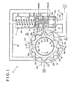
- FIG. 1 is a conceptual arrangement of an oil supply system of this embodiment of the present invention.
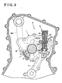
- Fig. 2 is a schematic layout of the oil supply system of the present invention mounted in the engine.
- the oil supply system X for the engine of the present invention is provided with a pump body 1 including an inlet port 36 suctioning a hydraulic oil in response to the rotation of a rotor 2 driven by synchronizing with a crankshaft, a first outlet port 31 discharging the hydraulic oil and a second outlet port 32 discharging the hydraulic oil therefrom.
- the oil supply system X for the engine is further provided with a hydraulic-oil-delivery passage 5 for delivering the hydraulic oil to a hydraulic-oil receiving unit 7, a first oil passage 61 for delivering the hydraulic oil discharged out of the first outlet port 31 to the hydraulic-oil-delivery passage 5 at least and a second oil passage 62 for delivering the hydraulic oil discharged out of the second outlet port 32 to the hydraulic-oil-delivery passage 5.
- the oil supply system for the engine is further provided with a return hydraulic passage 66 returning the hydraulic oil discharged out of a hydraulic-pressure control valve 4 including a valve 47 which is moved in response to hydraulic pressure of the hydraulic oil delivered to the hydraulic-oil-delivery passage 5, to at least either the inlet port 36 or a oil pan 69.
- the pump body 1 according to the oil supply system X is made of metal, such as an aluminum-based alloy and an iron-based alloy.
- a pump chamber 10 is formed in the pump body 1.
- an internal gear portion 12 having a plurality of inner gears 11 serving as a driven gear is formed.
- the rotor 2 made of metal is rotatably disposed therein.
- the rotor 2 is connected to the crankshaft of the internal combustion engine which constitutes the driving force, and rotates with the crankshaft.
- the rotor 2 is designed to rotate at 600 rpm to 7000 rpm.
- an outer gear portion 22 having a plurality of external gears 21 serving as the drive gear is formed on an outer periphery of the rotor 2.
- the internal gears 11 and the external gears 21 are defined by such as a trochoid curve or a cycloidal curve.
- the rotor 2 rotates in a direction of an arrow "A1" as illustrated Fig. 1.
- the external gears 21 of the rotor 2 mesh with the internal gears 11 one after another in response to the rotation of the rotor 2. Accordingly the internal gears 12 rotates in the same direction.
- Spaces 22a through 22k are formed by the external gears 21 and the internal gears 11. In Fig. 1, the space 22k has the largest volume among the spaces 22a through 22k, and the space 22e and 22f have the smallest volume.
- spaces 22e through 22a go downstream, their volume is enlarged gradually as the rotor 2 rotates. An inlet pressure of the hydraulic oil is produced thereby and an inlet action of the hydraulic oil is obtained. In spaces 22j through 22f, the discharging pressure is produced since their volume is diminished gradually when the rotor 2 rotates.
- an outlet port group 33 is formed by the first outlet port 31 (i.e., a main outlet port) and the second outlet port 32 (i.e., a sub-outlet port). That is, the outlet port group 33 serves as discharging the hydraulic oil from the pump chamber 10 in response to the rotation of the rotor 2.
- the main outlet port 31 is provided with end sides 31a and 31c.
- the sub-outlet port 32 is provided with end sides 32a and 32c.
- the inlet port 36 is formed as well.
- the inlet port 36 serves to suction the hydraulic oil into the pump body 10 in response to the rotation of the rotor 2.
- the inlet port 36 is provided with end sides 36a and 36c.
- the main outlet port 31 is located at the downstream side relative to the sub-outlet port 32 in the rotary direction of the rotor 2 indicated by the arrow "A1".
- An open area of the main outlet port 31 is set to be larger than the open area of the sub-outlet port 32.
- the main outlet port 31 and the sub-outlet port 32 are divided by a dividing portion 37. Thereby the main outlet port 31 and the sub-outlet port 32 have independent discharging-function respectively.
- the width of the dividing portion 37 is set to be narrower than the width of space between inner and outer gears at the area between the main outlet port 31 and the sub-outlet port 32.
- the hydraulic-oil-delivery passage 5 is a hydraulic-oil passage delivering the hydraulic oil to the hydraulic-oil receiving unit 7.
- the hydraulic-oil receiving unit 7 may be a lubricating device such as a bearing, a valve operation mechanism for an internal combustion engine or a driving mechanism such as a cylinder and a piston of the internal combustion engine, which are required to supply the hydraulic oil.
- the first oil passage 61 is the oil passage which connects the main outlet port 31 to the hydraulic-oil-delivery passage 5. That is, the first oil passage 61 has the function which delivers the hydraulic oil discharged out of the main outlet port 31 to the hydraulic-oil-delivery passage 5.
- the second oil passage 62 is the oil passage which connects the sub-outlet port 32 to the hydraulic-oil-delivery passage 5. That is, the second oil passage 62 has the function which delivers the hydraulic oil discharged out of the sub-outlet port 32 to the hydraulic-oil-delivery passage 5.
- Fig. 1 shows an example of the function that the hydraulic oil discharged out of the sub-outlet port 32 flows through the hydraulic-pressure control valve 4 and the main outlet port 31, then flows to the hydraulic-oil-delivery passage 5 via the first oil passage 61.
- the return hydraulic passage 66 is an oil passage which returns the hydraulic oil discharged out of the hydraulic control valve 4 to any one of the inlet port 36 and an oil pan 69.
- a passage 66n which suctions the hydraulic oil out of the oil pan 69 is disposed in communication with the inlet port 36.
- the hydraulic-pressure control valve 4 is provided with a valve 47 which moves in response to the hydraulic pressure of the hydraulic oil delivered to the hydraulic-oil-delivery passage 5.
- the hydraulic control valve 4 is further provided with a valve chamber 40 in which the valve 47 is freely slidable. In the valve chamber 40, the valve 47 is disposed by biased by a spring 49 in the direction of the arrow "B1".
- a first valve portion 47x and a second valve portion 47y which compose a hydraulic-oil receiving portion 48 which receives the hydraulic oil within hydraulic-pressure control valve 4 are disposed. Further in the valve 47, a dividing body 47a which divides the hydraulic-oil receiving portion 48 into a first valve chamber 48a and a second valve chamber 48b is disposed.
- a first valve port 41, a second valve port 42, return ports 43a and 43b and a merging port 44 which communicate with each described oil passage are disposed.
- the first valve port 41 communicates with the first oil passage 61 and the hydraulic-oil-delivery passage 5 via an intermediate oil passage 61r.
- the hydraulic pressure of the hydraulic oil can be transmitted to the valve 47 via the intermediate oil passage 61 thereby.
- the second valve port 42 is capable of communicating with the second oil passage 62.
- the hydraulic oil discharged out of the second outlet port 32 can be discharged to the hydraulic-oil receiving portion 48 thereby.
- the return ports 43a and 43b are capable of communicating with the return hydraulic passage 66.
- the hydraulic discharged out of the hydraulic control valve 4 can be returned to the inlet port 36 thereby.
- the merging port 44 is capable of communicating with the main outlet port 31 so as to deliver the hydraulic oil discharged out of the hydraulic-pressure control valve 4 to the main outlet port 31.
- the valve 47 of the hydraulic-pressure control valve 4 have five modes i.e., modes A through E, according to the rotational speed of the rotor 2 as described hereinbelow.
- the first valve portion 47x of the valve 47 blocks the return port 43a and the second valve portion 47y of the valve 47 blocks the return port 43b respectively.
- the second valve port 42 is in communication with the merging port 44 as shown in Fig. 3.
- the hydraulic oil discharged out of the sub-outlet port 32 can be delivered to the hydraulic-oil-delivery passage 5 via the first valve chamber 48a. That is, the hydraulic oil discharged out of the sub-outlet port 32 can be delivered to the hydraulic-oil-delivery passage 5 via the first valve chamber 48a when the hydraulic pressure delivered to the hydraulic-oil-delivery passage 5 is within a predetermined value.
- a supply amount of the hydraulic oil delivering to the hydraulic-oil-delivery passage 5 is the total amount of the discharging amount of the main outlet port 31 and the discharging amount of the sub-outlet port 32.
- An oil amount delivered to the hydraulic-oil-delivery passage 5 has a characteristic performance as shown by a solid line O-P in Fig. 8. That is, the discharging amount of the hydraulic oil discharged out of the main outlet port 31 increases according to the increase of the rotational speed of the rotor 2. Further, the discharging amount of the hydraulic oil discharged out of the sub-outlet port 32 increases according to the increase of the hydraulic pressure in the first oil passage 61. The characteristic performance that the hydraulic pressure in the second oil passage 62 increases can be obtained.
- the rotational speed of the rotor 2 increases according to the increase of the rotational speed of the crankshaft of the internal combustion engine working as the driving power force.
- N1 predetermined rotational speed
- the valve driving force "F1” overcomes the biasing force "F3" of the spring 49 (F1 > F3)
- the valve 47 moves in the direction of an arrow "B2” until the valve driving force "F1” and the urging force "F3” of the spring 49 balance (see Fig. 1).
- the mode “B” shows an intermediate mode wherein the valve 47 is shifting to the mode "C” described later.
- the hydraulic oil discharged out of the sub-outlet port 32 can be delivered to the return hydraulic passage 66 in part and the rest is delivered to the hydraulic-oil-delivery passage 5 via the first valve chamber 48a.
- the supply amount of the hydraulic oil delivered to the hydraulic-oil-delivery passage 5 is the total discharging amounts of the main outlet port 31 and the discharging amount of the sub-outlet port 32.
- the oil amount delivered to the hydraulic-oil-delivery passage 5 has a characteristic performance as indicated by a solid line P-Q in Fig. 8. Accordingly, a rate of the increase in the discharging amount relative to the increase of the rotational speed of the rotor reduces since a passage returning to the return hydraulic passage 66 communicates.
- a relationship between a required oil amount of a variable valve timing control device working as the hydraulic-oil receiving unit 7 and the rotational speed of the rotor in the engine will be described hereinbelow.
- the total discharged amount which adds the discharging amount of the sub-outlet port 32 to the discharging amount of the main outlet port 31 is required.
- the rotational speed of the rotor exceeds the predetermined rotational speed (N1), the total discharged amount is not required.
- the required oil amount can be provided by the discharging amount of the main outlet port 31 only (i.e., an area shown by "V" in Fig. 8). Accordingly, it is preferable that the oil supply system X is composed so that each inclination of line O-P and line P-Q shown in Fig. 8 can exceed the required oil amount V required for the variable valve timing control device.
- the hydraulic oil discharged out of the main outlet port 31 is delivered to the hydraulic-oil-delivery passage 5.
- the hydraulic oil discharged out of the sub-outlet port 32 can be delivered to the return hydraulic passage 66 via the first valve chamber 48a.
- the oil amount delivered to the hydraulic-oil-delivery passage 5 has a characteristic performance as indicated by a solid line Q-R in Fig. 8. That is, in the mode "C", the oil amount delivered to the hydraulic-oil-delivery passage 5 is equal to the oil amount discharged out of the main outlet port 31.
- the second valve port 42 communicates with the merging port 44 and the dividing chamber 47a prevents the hydraulic oil from moving to the return port 43a. Accordingly, the hydraulic oil discharged out of the sub-outlet port 32 can be delivered to the hydraulic-oil-delivery passage 5 via the second valve chamber 48b.
- the hydraulic oil discharged out of the sub-outlet port 32 can be delivered to the hydraulic-oil-delivery passage 5 via the second valve chamber 48b.
- the supply amount of the hydraulic oil delivered to the hydraulic-oil-delivery passage 5 is the total amount of the discharging amounts discharged out of the main outlet port 31 and the sub-outlet port 32.
- the oil amount delivered to the hydraulic-oil-delivery passage 5 has a characteristic performance as indicated by a solid line R-T in Fig. 8.
- the hydraulic oil delivered to stops flowing to the return port 43a After that reason, the flowing route of the hydraulic oil delivered to the return port 43a is changed to the hydraulic-oil-delivery passage 5. Therefore, the supply amount delivered to the hydraulic-oil-delivery passage 5 increases (see a solid line R-S in Fig. 8) and becomes the total amount of the discharging amounts discharged out of the main outlet port 31 and the sub-outlet port 32 (i.e., a solid line S-T in Fig. 8).
- the total amount is a part of the discharging amount of the main outlet port 31 and a part of the discharging amount of the sub-outlet port 32.
- the oil amount delivered to the hydraulic-oil-delivery passage 5 has a characteristic performance as indicated by a solid line T-U in Fig. 8.
- the rate of the increase in the discharging amount relative to the increase of the rotational speed of the rotor reduces since the passages returning to the return hydraulic passage 66 are in open communication.
- the required oil amount of a jet for a piston operating as the hydraulic-oil receiving unit 7 and the rotational speed of the rotor will be described hereinbelow.
- the total discharging amount of the discharging amount of the main outlet port 31 and the sub-outlet port 32 is required around the high-speed area in the rotation of the rotor.
- the rotational speed of the rotor exceeds the predetermined rotational speed (N4) of the rotor, the total discharging amount is not required (i.e., an area shown by "W" in Fig. 8).
- the oil supply system X is composed so that the inclination of the line T-U shown in Fig. 8 can exceed the required oil amount "W" of the jet for the piston.
- the hydraulic oil discharged out of the sub-outlet port 32 can be delivered to the hydraulic-oil-delivery passage 5 via the first valve chamber 48a.
- the supply amount of hydraulic oil delivered to the hydraulic-oil-delivery passage 5 is the amount wherein the discharging amount discharged out of the main outlet port 31 and the discharging amount discharged out of the sub-outlet port 32 are added (i.e., the solid line O-P shown in Fig. 8).
- the required hydraulic pressure is secured up in the first oil passage 61 only, the required hydraulic pressure is returned to the return oil hydraulic passage 66 without delivering the extra hydraulic oil in the second oil passage 62 to the hydraulic-oil-delivery passage 5.
- the high hydraulic pressure does not affect the extra hydraulic oil.
- the hydraulic oil is required to supply to a lot of pistons immediately.
- the oil supply system X is composed so that the hydraulic oil discharged out of the sub-outlet port 32 can be delivered to the hydraulic-oil-delivery passage 5 via the second valve chamber 48b.
- the supply amount of the hydraulic oil delivering to the hydraulic-oil-delivery passage 5 is the added amount of the discharging amount of the main outlet port 31 and the discharging amount of the sub-outlet port 32 (i.e., a solid line S-T shown in Fig. 8).
- a moving-direction dimension L1 of the first valve chamber 48a and a moving-direction dimension L2 of the second valve chamber 48b are designed as follows.
- a design method of the moving-direction dimension L1 of the first valve chamber 48a will be illustrated by an example.
- the second valve port 42 communicates with the merging port 44. That is, the first valve chamber 48a communicates with the first outlet port 31.
- the oil supply system X is composed so as to keep the return port 43a closing.
- the second valve port 42 communicates with the merging port 44, and the return port 43a is secured closing by slidably moving of the valve 47 in the valve chamber 40. That is, the first valve chamber 48a is composed so as to communicate with the return hydraulic passage 66.
- the first valve chamber 48a when the first valve chamber 48a communicates with the second oil passage 62, the first valve chamber 48a is composed so as to communicate with at least either first outlet port 31 or return hydraulic passage 66.
- the merging port 44 starts communicating with the second valve port 42 at just an under surface of the dividing chamber 47a defining an under surface of the first valve chamber 48a and an upper surface of the second valve chamber 48b, i.e., the second calve chest 48b.
- the second valve port 42 communicates with the merging port 44, and the return port 43a is secured closing. That is, the second valve chamber 48b is composed so as to communicate with the return hydraulic passage 66.
- the second valve chamber 48b when the second valve chamber 48b communicates with the second oil passage 62, the second valve chamber 48b is composed so as to communicate with at least either first outlet port 31 or return hydraulic passage 66.
- the moving-direction dimension L1 of the first valve chamber 48a and the moving-direction dimension L2 of the second valve chamber 48b require a relationship of an accurate dimension.
Abstract
Description
- This invention generally relates to an oil supply system for an engine. More specifically, this invention relates to an oil supply system for an engine provided with a pump body including an inlet port suctioning hydraulic oil in response to the rotation of a rotor driven by synchronizing with a crankshaft and first and second outlet ports discharging the hydraulic oil in response to the rotation of the rotor. The oil supply system for the engine is further provided with a hydraulic-oil-delivery passage for delivering the hydraulic oil to a hydraulic-oil receiving unit, a first oil passage for delivering the hydraulic oil discharged out of at least the first outlet port to the hydraulic-oil-delivery passage and a second oil passage for delivering the hydraulic oil discharged out of the second outlet port to the hydraulic-oil-delivery passage. Furthermore, the oil supply system for the engine is further provided with a return hydraulic passage returning the hydraulic oil discharged out of a hydraulic-pressure control valve including a valve which is moved in response to hydraulic pressure of the hydraulic oil delivered to the hydraulic-oil-delivery passage, to at least either the inlet port or an oil pan.
- In an engine for vehicles, an oil pump (i.e., an oil supply system) delivering the hydraulic oil to be used for lubrication of the engine to each portion of the engine has a variable discharge volume structure variably adjusting discharging pressure in response to the rotation of the engine. The above mentioned oil supply system is shown in JPH08 (1996)-114186A and JP2598994Y.
- For example, the oil supply system described in JPH08 (1996)-114186A is provided with an oil pump including the first outlet port and the second outlet port discharging the hydraulic oil in response to the rotation of the rotor and the hydraulic-oil-delivery passage delivering the hydraulic oil to the hydraulic-oil receiving unit. The oil supply system is further provided with the first oil passage delivering the hydraulic oil discharged out of the first outlet port to the hydraulic-oil-delivery passage, the second oil passage delivering the hydraulic oil discharged out of the second outlet port to the hydraulic-oil-delivery passage and the return oil passage returning the hydraulic oil discharged out of the second outlet port to the oil pump. Furthermore, the oil supply system includes a control valve including the valve operable in response to the hydraulic pressure of the hydraulic oil of the first oil passage.
- When the hydraulic pressure of the first oil passage is lower than a predetermined value, this control valve delivers the hydraulic oil via both the first oil passage and the second oil passage to the hydraulic-oil-delivery passage (i.e., a first mode). When the hydraulic pressure of the first oil passage is higher than the predetermined value, the control valve prevents the merging of the hydraulic oil flow in the first and the second oil passages and allows the hydraulic-oil in the first oil passage to be delivered to the hydraulic-oil -delivery passage, and forces the hydraulic oil in the second oil passage to be returned to the return oil passage (i.e., a second mode). Accordingly, the oil supply system is capable of switching from the first mode to the second mode or vice versa.
- As shown in Fig. 9, while the rotational speed of the rotor in the engine is in a low speed area lower than a predetermined speed (N1) (i.e., when the hydraulic pressure of the first oil passage is lower than the predetermined value), the discharged amount of the hydraulic oil discharged out of the oil supply system has a characteristic similar to a dotted line "a". In other words, a supply amount of the hydraulic oil delivered to the hydraulic-oil-delivery passage is a total amount of the discharging amount of the first outlet port (i.e., a main outlet port) and the discharging amount of the second outlet port (i.e., a sub-outlet port) (i.e., the first mode).
- In a first medium speed area starting from a point "Y" exceeding the predetermined speed (N1), the valve slides within the control valve according to the increase of the hydraulic pressure in the first oil passage, and a passage for returning to the return oil passage is open for communication. A rate of the increase of the discharging amount relative to the increase of the rotational speed becomes smaller (see a solid line "Y-Z" shown in Fig. 9).
- When the rotational speed of the rotor further increases and reaches at a point "Z" which is a second medium speed area, the valve further slides in the control valve to prevent merging of the hydraulic oil in the first oil passage and the second oil passage (i.e., the second mode). In this case, the discharging amount of the hydraulic oil discharged out of the oil supply system is on a chain line "b" in Fig. 9 which shows the discharging amount at the first outlet port. In a high-speed area, thereafter, the discharging amount has an approximately similar characteristic to the chain line "b" thereafter. That is, the supply amount of the hydraulic oil delivered to the hydraulic-oil-delivery passage becomes approximately equal to the discharging amount of the first outlet port.
- In the first mode, even when the rotational speed of the rotor is low, the required hydraulic pressure delivered to the hydraulic-oil receiving unit is secured by merging of the hydraulic oil in the first oil passage and the hydraulic oil in the second oil passage.
- On the other hand, when the discharging amount discharged out of the first outlet port increases in response to the increase of the rotational speed of the rotor and the required hydraulic pressure is secured by the first oil passage only, the first mode is shifted to the second mode wherein the extra hydraulic oil discharged out of the second outlet port in the second oil passage is returned to the inlet port side via the return oil passage. As mentioned above, if the extra hydraulic oil is returned to the return oil passage from the second oil passage without delivering to the hydraulic-oil-delivery passage, the extra hydraulic oil would not be affected by a large hydraulic pressure: Accordingly, when the required hydraulic pressure is secured by the first oil passage only, an additional work in the oil pump device can be reduced or avoided and the driving horsepower of the oil supply system can be reduced.
- According to the oil supply system disclosed in JPH08 (1996)-114186A, when an oil temperature of the hydraulic oil raises e.g., up to 130 degrees Celsius by increasing of the rotational speed of the rotor after the engine has been started, viscosity of the hydraulic oil becomes less and the hydraulic oil can easily be supplied to the spaces between each portion in the hydraulic-oil receiving unit. This will cause the increase of so-called oil leakage.
- As shown in Fig. 9, when the rotational speed of the rotor in the engine increases and reaches at a point "Z", the discharging amount of the hydraulic oil discharged out of the oil supply system indicated by a solid line in Fig. 9 has an approximately similar characteristic performance to the chine line "b" showing the discharging amount of the first outlet port. The difference between the chine line "b" and the solid line arises due to the oil leakage.
- That is, viscosity of the hydraulic oil becomes more less in response to further increase of the rotational speed of the rotor, and an oil leakage phenomenon may occur frequently. In order to prevent this, however, there is a problem that it is difficult to keep the required oil amount for keeping the hydraulic pressure for a jet for a piston and a crank journal in the hydraulic-oil receiving unit.
- Especially, in the jet for the piston, when the rotor rotates at a high speed, it is required to supply much hydraulic oil to the piston immediately. For that purpose, when the rotor rotates at high speed, it is preferable that the required oil amount corresponds to the discharging amount of the hydraulic oil discharged out of the oil supply system i.e., the total discharging amount (shown by a dotted line "a" in Fig. 9) adding up the discharging amount of the first and second outlet ports.
- A need exists for providing an improved oil supply system capable of securing sufficiently a required oil amount for delivering to the hydraulic-oil receiving unit to, even when the engine rotates at high speed.
- According to an aspect of a present invention, an oil supply system for an engine includes a pump body including an inlet port for suctioning a hydraulic oil in response to the rotation of a rotor driven by synchronizing with a crankshaft, a first outlet port for discharging the hydraulic oil and a second outlet port for discharging the hydraulic oil in response to the rotation of the rotor and a hydraulic-oil-delivery passage for delivering the hydraulic oil to a hydraulic-oil receiving unit. The oil supply system for the engine further includes a first oil passage for delivering the hydraulic oil discharged out of the first outlet port to the hydraulic-oil-delivery passage, a second oil passage for delivering the hydraulic oil discharged out of the second outlet port to the hydraulic-oil-delivery passage and a return hydraulic passage for returning the hydraulic oil discharged out of a hydraulic-pressure control valve including a valve body which is moved in response to the hydraulic pressure delivered to the hydraulic-oil-delivery passage, to at least either the inlet port or an oil pan. The valve body divides a hydraulic-oil receiving portion for receiving the hydraulic oil in the hydraulic-pressure control valve chamber into a first valve chamber and a second valve chamber. When the hydraulic pressure oil delivered to the hydraulic-oil-delivery passage is in a predetermined value, the hydraulic oil discharged out of the second outlet port is delivered to the hydraulic-oil-delivery passage via the first valve chamber. Further when the hydraulic pressure delivered to the hydraulic-oil-delivery passage exceeds the predetermined value, the hydraulic oil discharged out of the second outlet port is delivered to the hydraulic-oil-delivery passage via the second valve chamber.
- The foregoing and additional features and characteristics of the present invention will become more apparent from the following detailed description considered with reference to the accompanying drawings, wherein:
- Fig. 1 is a conceptual arrangement of an oil supply system of the present invention;
- Fig. 2 is a schematic layout when an engine of the oil supply system of the present invention is mounted;
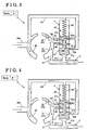
- Fig. 3 is a substantial-part schematic diagram of the oil supply system of the present invention in a case that a rotational speed of the rotor is in a low speed area (a mode "A");
- Fig. 4 is a schematic diagram of a main part of the oil supply system of the present invention in a case that a rotational speed of the rotor is in a first medium speed area (a mode "B");
- Fig. 5 is a schematic diagram of a main part of the oil supply system of the present invention in a case that the rotational speed of the rotor is in another first medium speed area (a mode "C");
- Fig. 6 is a schematic diagram of a main part of the oil supply system of the present invention in a case that the rotational speed of the rotor is in a second medium speed area (a mode "D");
- Fig. 7 is a schematic diagram of a main part of the oil supply system of the present invention in a case that the rotational speed of the rotor is in a high speed area (a mode "E");
- Fig. 8 is a graph showing a relationship between the rotational speed of the rotor in the engine and a discharging amount of a hydraulic oil in an outlet port group; and
- Fig. 9 is a graph showing a relationship between the rotational speed of the rotor in the engine and the discharging amount of the hydraulic oil in conventional oil supply systems.
-
- The present invention is described in further detail below with reference to an embodiment according to the accompanying drawings. This embodiment illustrates an oil supply system which generates hydraulic pressure by the rotation of a crankshaft in an internal combustion engine mounted in a vehicle. Fig. 1 is a conceptual arrangement of an oil supply system of this embodiment of the present invention. Fig. 2 is a schematic layout of the oil supply system of the present invention mounted in the engine.
- As illustrated in Figs. 1 and 2, the oil supply system X for the engine of the present invention is provided with a
pump body 1 including aninlet port 36 suctioning a hydraulic oil in response to the rotation of arotor 2 driven by synchronizing with a crankshaft, afirst outlet port 31 discharging the hydraulic oil and asecond outlet port 32 discharging the hydraulic oil therefrom. The oil supply system X for the engine is further provided with a hydraulic-oil-delivery passage 5 for delivering the hydraulic oil to a hydraulic-oil receiving unit 7, afirst oil passage 61 for delivering the hydraulic oil discharged out of thefirst outlet port 31 to the hydraulic-oil-delivery passage 5 at least and asecond oil passage 62 for delivering the hydraulic oil discharged out of thesecond outlet port 32 to the hydraulic-oil-delivery passage 5. Furthermore, the oil supply system for the engine is further provided with a returnhydraulic passage 66 returning the hydraulic oil discharged out of a hydraulic-pressure control valve 4 including avalve 47 which is moved in response to hydraulic pressure of the hydraulic oil delivered to the hydraulic-oil-delivery passage 5, to at least either theinlet port 36 or aoil pan 69. Each member will be illustrated hereinbelow. - The
pump body 1 according to the oil supply system X is made of metal, such as an aluminum-based alloy and an iron-based alloy. In thepump body 1, apump chamber 10 is formed. In thepump chamber 10, aninternal gear portion 12 having a plurality ofinner gears 11 serving as a driven gear is formed. - In the
pump chamber 10, therotor 2 made of metal is rotatably disposed therein. Therotor 2 is connected to the crankshaft of the internal combustion engine which constitutes the driving force, and rotates with the crankshaft. Therotor 2 is designed to rotate at 600 rpm to 7000 rpm. - On an outer periphery of the
rotor 2, anouter gear portion 22 having a plurality ofexternal gears 21 serving as the drive gear is formed. The internal gears 11 and theexternal gears 21 are defined by such as a trochoid curve or a cycloidal curve. Therotor 2 rotates in a direction of an arrow "A1" as illustrated Fig. 1. The external gears 21 of therotor 2 mesh with theinternal gears 11 one after another in response to the rotation of therotor 2. Accordingly theinternal gears 12 rotates in the same direction.Spaces 22a through 22k are formed by theexternal gears 21 and the internal gears 11. In Fig. 1, thespace 22k has the largest volume among thespaces 22a through 22k, and thespace - When
spaces 22e through 22a go downstream, their volume is enlarged gradually as therotor 2 rotates. An inlet pressure of the hydraulic oil is produced thereby and an inlet action of the hydraulic oil is obtained. Inspaces 22j through 22f, the discharging pressure is produced since their volume is diminished gradually when therotor 2 rotates. - In the
pump body 1 of the oil pump, anoutlet port group 33 is formed by the first outlet port 31 (i.e., a main outlet port) and the second outlet port 32 (i.e., a sub-outlet port). That is, theoutlet port group 33 serves as discharging the hydraulic oil from thepump chamber 10 in response to the rotation of therotor 2. Themain outlet port 31 is provided withend sides sub-outlet port 32 is provided withend sides - Further, in the
pump body 1 of the oil pump, theinlet port 36 is formed as well. Theinlet port 36 serves to suction the hydraulic oil into thepump body 10 in response to the rotation of therotor 2. Theinlet port 36 is provided withend sides - In this preferred embodiment, the
main outlet port 31 is located at the downstream side relative to thesub-outlet port 32 in the rotary direction of therotor 2 indicated by the arrow "A1". An open area of themain outlet port 31 is set to be larger than the open area of thesub-outlet port 32. - The
main outlet port 31 and thesub-outlet port 32 are divided by a dividingportion 37. Thereby themain outlet port 31 and thesub-outlet port 32 have independent discharging-function respectively. - The width of the dividing
portion 37 is set to be narrower than the width of space between inner and outer gears at the area between themain outlet port 31 and thesub-outlet port 32. Thus, the hydraulic pressure increase caused by blocking the space in the compression stage can be avoided. - The hydraulic-oil-
delivery passage 5 is a hydraulic-oil passage delivering the hydraulic oil to the hydraulic-oil receiving unit 7. The hydraulic-oil receiving unit 7 may be a lubricating device such as a bearing, a valve operation mechanism for an internal combustion engine or a driving mechanism such as a cylinder and a piston of the internal combustion engine, which are required to supply the hydraulic oil. - The
first oil passage 61 is the oil passage which connects themain outlet port 31 to the hydraulic-oil-delivery passage 5. That is, thefirst oil passage 61 has the function which delivers the hydraulic oil discharged out of themain outlet port 31 to the hydraulic-oil-delivery passage 5. - The
second oil passage 62 is the oil passage which connects thesub-outlet port 32 to the hydraulic-oil-delivery passage 5. That is, thesecond oil passage 62 has the function which delivers the hydraulic oil discharged out of thesub-outlet port 32 to the hydraulic-oil-delivery passage 5. - Fig. 1 shows an example of the function that the hydraulic oil discharged out of the
sub-outlet port 32 flows through the hydraulic-pressure control valve 4 and themain outlet port 31, then flows to the hydraulic-oil-delivery passage 5 via thefirst oil passage 61. - The return
hydraulic passage 66 is an oil passage which returns the hydraulic oil discharged out of thehydraulic control valve 4 to any one of theinlet port 36 and anoil pan 69. - In addition, a
passage 66n which suctions the hydraulic oil out of theoil pan 69 is disposed in communication with theinlet port 36. - The hydraulic-
pressure control valve 4 is provided with avalve 47 which moves in response to the hydraulic pressure of the hydraulic oil delivered to the hydraulic-oil-delivery passage 5. Thehydraulic control valve 4 is further provided with avalve chamber 40 in which thevalve 47 is freely slidable. In thevalve chamber 40, thevalve 47 is disposed by biased by aspring 49 in the direction of the arrow "B1". - At both ends of the
valve 47, afirst valve portion 47x and asecond valve portion 47y which compose a hydraulic-oil receiving portion 48 which receives the hydraulic oil within hydraulic-pressure control valve 4 are disposed. Further in thevalve 47, a dividingbody 47a which divides the hydraulic-oil receiving portion 48 into afirst valve chamber 48a and asecond valve chamber 48b is disposed. - In the hydraulic-
pressure control valve 4, afirst valve port 41, asecond valve port 42, returnports port 44 which communicate with each described oil passage are disposed. - The
first valve port 41 communicates with thefirst oil passage 61 and the hydraulic-oil-delivery passage 5 via anintermediate oil passage 61r. The hydraulic pressure of the hydraulic oil can be transmitted to thevalve 47 via theintermediate oil passage 61 thereby. - The
second valve port 42 is capable of communicating with thesecond oil passage 62. The hydraulic oil discharged out of thesecond outlet port 32 can be discharged to the hydraulic-oil receiving portion 48 thereby. - The
return ports hydraulic passage 66. The hydraulic discharged out of thehydraulic control valve 4 can be returned to theinlet port 36 thereby. - The merging
port 44 is capable of communicating with themain outlet port 31 so as to deliver the hydraulic oil discharged out of the hydraulic-pressure control valve 4 to themain outlet port 31. - In the oil supply system X for the engine of the present invention described above, the
valve 47 of the hydraulic-pressure control valve 4 have five modes i.e., modes A through E, according to the rotational speed of therotor 2 as described hereinbelow. - The mode "A" will be described with reference to Fig. 3. When the
rotor 2 rotates at low speed (e.g., up to about 1500 rpm) immediately after the engine has just driven, the hydraulic oil is delivered to the hydraulic-oil-delivery passage 5 by the hydraulic pressure of the hydraulic oil of thefirst oil passage 61 discharged out of theoutlet port group 33. This hydraulic pressure acts on thevalve 47 via theintermediate oil passage 61r and thefirst valve port 41 of the hydraulic-pressure control valve 4. Valve driving force "F1" is generated thereby to drive thevalve 47. When the valve driving force "F1" is smaller than biasing force "F3" of the spring 49 (i.e., F1 > F3), thevalve 47 moves in the direction of the arrow "B1" (see Fig. 1). - Under this condition, the
first valve portion 47x of thevalve 47 blocks thereturn port 43a and thesecond valve portion 47y of thevalve 47 blocks thereturn port 43b respectively. Further thesecond valve port 42 is in communication with the mergingport 44 as shown in Fig. 3. Thus the hydraulic oil discharged out of thesub-outlet port 32 can be delivered to the hydraulic-oil-delivery passage 5 via thefirst valve chamber 48a. That is, the hydraulic oil discharged out of thesub-outlet port 32 can be delivered to the hydraulic-oil-delivery passage 5 via thefirst valve chamber 48a when the hydraulic pressure delivered to the hydraulic-oil-delivery passage 5 is within a predetermined value. - According to the mode "A", a supply amount of the hydraulic oil delivering to the hydraulic-oil-
delivery passage 5 is the total amount of the discharging amount of themain outlet port 31 and the discharging amount of thesub-outlet port 32. An oil amount delivered to the hydraulic-oil-delivery passage 5 has a characteristic performance as shown by a solid line O-P in Fig. 8. That is, the discharging amount of the hydraulic oil discharged out of themain outlet port 31 increases according to the increase of the rotational speed of therotor 2. Further, the discharging amount of the hydraulic oil discharged out of thesub-outlet port 32 increases according to the increase of the hydraulic pressure in thefirst oil passage 61. The characteristic performance that the hydraulic pressure in thesecond oil passage 62 increases can be obtained. - Secondly, the mode "B" will be described with reference to Fig. 4. The rotational speed of the
rotor 2 increases according to the increase of the rotational speed of the crankshaft of the internal combustion engine working as the driving power force. When the rotational speed of therotor 2 exceeds the predetermined rotational speed (N1: e.g., 1500 rpm) i.e., at a first medium speed area, and the valve driving force "F1" overcomes the biasing force "F3" of the spring 49 (F1 > F3), thevalve 47 moves in the direction of an arrow "B2" until the valve driving force "F1" and the urging force "F3" of thespring 49 balance (see Fig. 1). - As shown in Fig. 4, the condition that the
second valve port 42 and the mergingport 44 are in communication is maintained and the block of thereturn port 43a in thefirst valve portion 47x is released. That is, the mode "B" shows an intermediate mode wherein thevalve 47 is shifting to the mode "C" described later. The hydraulic oil discharged out of thesub-outlet port 32 can be delivered to the returnhydraulic passage 66 in part and the rest is delivered to the hydraulic-oil-delivery passage 5 via thefirst valve chamber 48a. - In the mode "B", the supply amount of the hydraulic oil delivered to the hydraulic-oil-
delivery passage 5 is the total discharging amounts of themain outlet port 31 and the discharging amount of thesub-outlet port 32. The oil amount delivered to the hydraulic-oil-delivery passage 5 has a characteristic performance as indicated by a solid line P-Q in Fig. 8. Accordingly, a rate of the increase in the discharging amount relative to the increase of the rotational speed of the rotor reduces since a passage returning to the returnhydraulic passage 66 communicates. - A relationship between a required oil amount of a variable valve timing control device working as the hydraulic-
oil receiving unit 7 and the rotational speed of the rotor in the engine will be described hereinbelow. For example, immediately after the engine starts, the total discharged amount which adds the discharging amount of thesub-outlet port 32 to the discharging amount of themain outlet port 31 is required. However, when the rotational speed of the rotor exceeds the predetermined rotational speed (N1), the total discharged amount is not required. The required oil amount can be provided by the discharging amount of themain outlet port 31 only (i.e., an area shown by "V" in Fig. 8). Accordingly, it is preferable that the oil supply system X is composed so that each inclination of line O-P and line P-Q shown in Fig. 8 can exceed the required oil amount V required for the variable valve timing control device. - Thirdly, the mode "C" will be described with reference to the accompany drawings. When the rotational speed of the rotor further increases to the value N2 or to exceed the value N2 (e.g., 2500 rpm); the
valve 47 further moves in the direction of the arrow "B2" (see Fig. 1). - As shown in Fig. 5, since the
second valve port 42 does not communicate with the mergingport 44. The block of thereturn port 43a in thefirst valve portion 47x of thevalve 47 is fully released. - That is, when the hydraulic pressure of the hydraulic oil flowing to the hydraulic-oil-
delivery passage 5 exceeds the predetermined value, the hydraulic oil discharged out of themain outlet port 31 is delivered to the hydraulic-oil-delivery passage 5. The hydraulic oil discharged out of thesub-outlet port 32 can be delivered to the returnhydraulic passage 66 via thefirst valve chamber 48a. - The oil amount delivered to the hydraulic-oil-
delivery passage 5 has a characteristic performance as indicated by a solid line Q-R in Fig. 8. That is, in the mode "C", the oil amount delivered to the hydraulic-oil-delivery passage 5 is equal to the oil amount discharged out of themain outlet port 31. - Fourth, the mode "D" will be described with reference to the accompany drawings. When the rotational speed of the rotor further increases to the value N3 or to exceed the value N3 i.e., a second medium speed area (e.g., 4000 rpm), the
valve 47 further moves in the direction of the arrow "B2" (see Fig. 1). - As shown in Fig. 6, the
second valve port 42 communicates with the mergingport 44 and the dividingchamber 47a prevents the hydraulic oil from moving to thereturn port 43a. Accordingly, the hydraulic oil discharged out of thesub-outlet port 32 can be delivered to the hydraulic-oil-delivery passage 5 via thesecond valve chamber 48b. - Under the condition that the hydraulic pressure of the hydraulic oil acting on the hydraulic-oil-
delivery passage 5 exceeds the predetermined value, the hydraulic oil discharged out of thesub-outlet port 32 can be delivered to the hydraulic-oil-delivery passage 5 via thesecond valve chamber 48b. - Therefore, in the mode "D", the supply amount of the hydraulic oil delivered to the hydraulic-oil-
delivery passage 5 is the total amount of the discharging amounts discharged out of themain outlet port 31 and thesub-outlet port 32. - The oil amount delivered to the hydraulic-oil-
delivery passage 5 has a characteristic performance as indicated by a solid line R-T in Fig. 8. After thesecond valve port 42 communicates with the mergingport 44, the hydraulic oil delivered to stops flowing to thereturn port 43a. For that reason, the flowing route of the hydraulic oil delivered to thereturn port 43a is changed to the hydraulic-oil-delivery passage 5. Therefore, the supply amount delivered to the hydraulic-oil-delivery passage 5 increases (see a solid line R-S in Fig. 8) and becomes the total amount of the discharging amounts discharged out of themain outlet port 31 and the sub-outlet port 32 (i.e., a solid line S-T in Fig. 8). - Lastly, the mode "E will be described with reference to the accompany drawings. When the rotational speed of the rotor further increases to the value N4 or to exceed the value N4 i.e., a high-speed area (e.g., 4500 rpm), the
valve 47 further moves in the direction of the arrow "B2" (see Fig. 1). - As shown in Fig. 7, the condition that the
second valve port 42 and the mergingport 44 are in communication with each other is maintained and the block of thereturn port 43b by thesecond valve portion 47y is released. Next, the block of thereturn port 43a by the dividingportion 47a is released. By this release, the hydraulic oil discharged out of thesub-outlet port 32 can be delivered to the returnhydraulic passage 66 via thesecond valve chamber 48b and thereturn port 43a and the hydraulic oil discharged out of themain outlet port 31 can be delivered to the returnhydraulic passage 66 via thereturn port 43b. - Therefore, in the mode "E", the total amount is a part of the discharging amount of the
main outlet port 31 and a part of the discharging amount of thesub-outlet port 32. - The oil amount delivered to the hydraulic-oil-
delivery passage 5 has a characteristic performance as indicated by a solid line T-U in Fig. 8. Thus, the rate of the increase in the discharging amount relative to the increase of the rotational speed of the rotor reduces since the passages returning to the returnhydraulic passage 66 are in open communication. - A relationship between the required oil amount of a jet for a piston operating as the hydraulic-
oil receiving unit 7 and the rotational speed of the rotor will be described hereinbelow. For example, the total discharging amount of the discharging amount of themain outlet port 31 and thesub-outlet port 32 is required around the high-speed area in the rotation of the rotor. However, when the rotational speed of the rotor exceeds the predetermined rotational speed (N4) of the rotor, the total discharging amount is not required (i.e., an area shown by "W" in Fig. 8). Accordingly, it is preferable that the oil supply system X is composed so that the inclination of the line T-U shown in Fig. 8 can exceed the required oil amount "W" of the jet for the piston. - There are summarized as follow. When the hydraulic pressure of the hydraulic oil working to the hydraulic-oil-
delivery passage 5 is in the predetermined value, the hydraulic oil discharged out of thesub-outlet port 32 can be delivered to the hydraulic-oil-delivery passage 5 via thefirst valve chamber 48a. The supply amount of hydraulic oil delivered to the hydraulic-oil-delivery passage 5 is the amount wherein the discharging amount discharged out of themain outlet port 31 and the discharging amount discharged out of thesub-outlet port 32 are added (i.e., the solid line O-P shown in Fig. 8). - When the rotational speed of the internal combustion engine and the rotational speed of the rotor increase, and the hydraulic pressure of the hydraulic oil discharged out of the
main outlet port 31 exceeds the predetermined value, the required hydraulic pressure working to the hydraulic-oil-delivery passage 5 is secured up by the hydraulic oil discharged out of themain outlet port 31 only. In this case, it is not required that the hydraulic oil discharged out of thefirst oil passage 61 and the hydraulic oil discharged out of thesecond oil passage 62 are added (i.e., two lines P-Q and Q-R shown in Fig. 8). - When the required hydraulic pressure is secured up in the
first oil passage 61 only, the required hydraulic pressure is returned to the return oilhydraulic passage 66 without delivering the extra hydraulic oil in thesecond oil passage 62 to the hydraulic-oil-delivery passage 5. The high hydraulic pressure does not affect the extra hydraulic oil. - On the other hand, when the rotational speed of the rotor is in the high-speed area, the hydraulic oil is required to supply to a lot of pistons immediately. For that purpose, when the hydraulic pressure of the hydraulic oil working to the hydraulic-oil-
delivery passage 5 exceeds the predetermined value in the present invention, the oil supply system X is composed so that the hydraulic oil discharged out of thesub-outlet port 32 can be delivered to the hydraulic-oil-delivery passage 5 via thesecond valve chamber 48b. The supply amount of the hydraulic oil delivering to the hydraulic-oil-delivery passage 5 is the added amount of the discharging amount of themain outlet port 31 and the discharging amount of the sub-outlet port 32 (i.e., a solid line S-T shown in Fig. 8). - Accordingly, even when the rotational speed of the rotor is in the high-speed area, the required oil amount for delivering is steadily secured since the volume of the hydraulic oil capable of delivering increases again.
- In the embodiment described above, a moving-direction dimension L1 of the
first valve chamber 48a and a moving-direction dimension L2 of thesecond valve chamber 48b are designed as follows. - A design method of the moving-direction dimension L1 of the
first valve chamber 48a will be illustrated by an example. - When the
first valve chamber 48a communicates with thesecond oil passage 62 in Fig. 3, thesecond valve port 42 communicates with the mergingport 44. That is, thefirst valve chamber 48a communicates with thefirst outlet port 31. The oil supply system X is composed so as to keep thereturn port 43a closing. - In Fig. 4, the
second valve port 42 communicates with the mergingport 44, and thereturn port 43a is secured closing by slidably moving of thevalve 47 in thevalve chamber 40. That is, thefirst valve chamber 48a is composed so as to communicate with the returnhydraulic passage 66. - Accordingly, when the
first valve chamber 48a communicates with thesecond oil passage 62, thefirst valve chamber 48a is composed so as to communicate with at least eitherfirst outlet port 31 or returnhydraulic passage 66. - On the other hand, a design method of the moving-direction dimension L2 of the
second valve chamber 48b will be illustrated by an example. - When the
valve 47 further slides thevalve chamber 40 relative to the mode illustrated in Fig. 5, the mergingport 44 starts communicating with thesecond valve port 42 at just an under surface of the dividingchamber 47a defining an under surface of thefirst valve chamber 48a and an upper surface of thesecond valve chamber 48b, i.e., thesecond calve chest 48b. - In Fig. 6, when the
second valve chamber 48b communicates with thesecond oil passage 62, the mergingport 44 communicates with thesecond valve port 42. That is, thesecond valve chamber 48b communicates with thefirst outlet port 31. The oil supply system X is composed so as to keep thereturn port 43a closing. - In Fig. 7, the
second valve port 42 communicates with the mergingport 44, and thereturn port 43a is secured closing. That is, thesecond valve chamber 48b is composed so as to communicate with the returnhydraulic passage 66. - Accordingly, when the
second valve chamber 48b communicates with thesecond oil passage 62, thesecond valve chamber 48b is composed so as to communicate with at least eitherfirst outlet port 31 or returnhydraulic passage 66. - For that purpose, the moving-direction dimension L1 of the
first valve chamber 48a and the moving-direction dimension L2 of thesecond valve chamber 48b require a relationship of an accurate dimension. - When such relationship of the accurate dimension is obtained, the pressure of the
second outlet port 32 excessively increases by closing of the second oil passage. Thereby, some inconvenience such as increase of driving horsepower and damage of the pump body raises. However, in this composition, the required oil amount can be delivered to the hydraulic-oil receiving unit 7 without exceeding of the hydraulic pressure. - It is explicitly stated that all features disclosed in the description and/or the claims are intended to be disclosed separately and independently from each other for the purpose of original disclosure as well as for the purpose of restricting the claimed invention independent of the composition of the features in the embodiments and/or the claims. It is explicitly stated that all value ranges or indications of groups of entities disclose every possible intermediate value or intermediate entity for the purpose of original disclosure as well as for the purpose of restricting the claimed invention, in particular as limits of value ranges.
Claims (5)
- An oil supply system (X) for an engine, comprisingcharacterized in that the valve body (47) divides a hydraulic-oil receiving portion for receiving the hydraulic oil in the hydraulic-pressure control valve (4) into a first valve chamber (48a) and a second valve chamber (48b), and when the hydraulic pressure oil delivered to the hydraulic-oil-delivery passage (5) is in a predetermined value, the hydraulic oil discharged out of the second outlet port (32) is delivered to the hydraulic-oil-delivery passage (5) via the first valve chamber (48a), and further when the hydraulic pressure delivered to the hydraulic-oil-delivery passage (5) exceeds the predetermined value, the hydraulic oil discharged out of the second outlet port (32) is delivered to the hydraulic-oil-delivery passage (5) via the second valve chamber (48b).a pump body (1) including an inlet port (36) for suctioning a hydraulic oil in response to the rotation of a rotor (2) driven by synchronizing with a crankshaft, a first outlet port (31) for discharging the hydraulic oil and a second outlet port (32) for discharging the hydraulic oil in response to the rotation of the rotor (2),a hydraulic-oil-delivery passage (5) for delivering the hydraulic oil to a hydraulic-oil receiving unit (7),a first oil passage (61) for delivering the hydraulic oil discharged out of the first outlet port (31) to the hydraulic-oil-delivery passage (5),a second oil passage (62) for delivering the hydraulic oil discharged out of the second outlet port (32) to the hydraulic-oil-delivery passage (5), anda return hydraulic passage (66) for returning the hydraulic oil discharged out of a hydraulic-pressure control valve (4) including a valve body (47) which is moved in response to the hydraulic pressure delivered to the hydraulic-oil-delivery passage (5), to at least either the inlet port (36) or an oil pan (69),
- An oil supply system (X) for an engine according to claim 1, wherein the first valve chamber (48a) is adapted to communicate with at least the first outlet port (31) or the return oil passage (66) when the first valve chamber (48a) communicates with the second oil passage (62).
- An oil supply system (X) for an engine according to claim 1 or 2, wherein the second valve chamber (48b) is adapted to communicate with at least the first outlet port (31) or the return oil passage (66) when the second valve chamber (48b) communicates with the second oil passage (62).
- An oil supply system (X) for an engine according to any one of the preceding claims, wherein the first valve chamber (48a) or the second valve chamber (48b) communicates with the first outlet port (31) and the return oil passage (66) when the first valve chamber (48a) or the second valve chamber (48b) communicates with the second oil passage (62).
- An oil supply system (X) for an engine according to any one of the preceding claims, wherein the first outlet port (31) and the second outlet port (32) are divided by a dividing portion (37), the width of the dividing portion (37) is set to be narrower than the width of space between inner and outer gears (11 and 12) at the area between the first outlet port (31 ) and the second outlet port (32).
Applications Claiming Priority (2)
| Application Number | Priority Date | Filing Date | Title |
|---|---|---|---|
| JP2003377530 | 2003-11-06 | ||
| JP2003377530A JP4366645B2 (en) | 2003-11-06 | 2003-11-06 | Engine oil supply device |
Publications (3)
| Publication Number | Publication Date |
|---|---|
| EP1529958A2 true EP1529958A2 (en) | 2005-05-11 |
| EP1529958A3 EP1529958A3 (en) | 2005-10-19 |
| EP1529958B1 EP1529958B1 (en) | 2008-01-02 |
Family
ID=34431324
Family Applications (1)
| Application Number | Title | Priority Date | Filing Date |
|---|---|---|---|
| EP04026034A Active EP1529958B1 (en) | 2003-11-06 | 2004-11-03 | Oil supply system for an IC engine |
Country Status (4)
| Country | Link |
|---|---|
| US (1) | US7011069B2 (en) |
| EP (1) | EP1529958B1 (en) |
| JP (1) | JP4366645B2 (en) |
| DE (1) | DE602004010989T2 (en) |
Cited By (9)
| Publication number | Priority date | Publication date | Assignee | Title |
|---|---|---|---|---|
| GB2452493A (en) * | 2007-09-05 | 2009-03-11 | Bamford Excavators Ltd | Pump with pressure relief in rotor support |
| EP1959143A3 (en) * | 2007-02-13 | 2009-09-16 | Yamada Manufacturing Co., Ltd. | Oil pump pressure control device |
| EP1961961A3 (en) * | 2007-02-20 | 2009-12-16 | Yamada Manufacturing Co., Ltd. | Oil pump pressure control device |
| CN101245722B (en) * | 2007-02-13 | 2011-02-09 | 株式会社山田制作所 | Oil pump pressure control device |
| US8454323B2 (en) | 2010-05-03 | 2013-06-04 | Geraete- Und Pumpenbau Gmbh Dr. Eugen Schmidt | Lubricant valve for oil pumps of internal combustion engines |
| US8691140B2 (en) | 2006-03-08 | 2014-04-08 | Sa Des Eaux Minerales D'evian Saeme | Process for injection molding of thin-walled preform |
| EP2600004A3 (en) * | 2011-12-02 | 2016-04-27 | Myunghwa Ind. Co., Ltd. | Variable oil pump |
| KR101724912B1 (en) * | 2015-09-30 | 2017-04-07 | 현대자동차주식회사 | Mechanical-variable relief oil pump structure |
| CN109469528A (en) * | 2018-12-28 | 2019-03-15 | 杭州电子科技大学 | A kind of change discharge capacity inner-rotor-type lubricating oil pump |
Families Citing this family (39)
| Publication number | Priority date | Publication date | Assignee | Title |
|---|---|---|---|---|
| DE10350632A1 (en) * | 2003-10-29 | 2005-06-16 | Gkn Sinter Metals Gmbh | Double or multiple pump |
| US8360746B2 (en) * | 2006-05-10 | 2013-01-29 | Metaldyne Company, Llc | Inverted pressure regulating valve for an engine oil pump |
| JP2007309234A (en) * | 2006-05-19 | 2007-11-29 | Honda Motor Co Ltd | Lubricating device for internal combustion engine |
| JP4687991B2 (en) | 2006-11-07 | 2011-05-25 | アイシン精機株式会社 | Engine oil supply device |
| KR100844460B1 (en) | 2007-07-11 | 2008-07-07 | (주)광일기공 | Extra oil pressure use oil pump |
| US11493037B1 (en) | 2014-05-21 | 2022-11-08 | Laverne Schumann | Pump system |
| US8801396B2 (en) | 2010-06-04 | 2014-08-12 | Chrysler Group Llc | Oil pump system for an engine |
| US9394901B2 (en) | 2010-06-16 | 2016-07-19 | Kevin Thomas Hill | Pumping systems |
| JP5535848B2 (en) * | 2010-09-16 | 2014-07-02 | 本田技研工業株式会社 | Engine with variable flow oil pump |
| JP5364068B2 (en) * | 2010-09-30 | 2013-12-11 | アイシン・エィ・ダブリュ工業株式会社 | Gear pump |
| KR101534878B1 (en) * | 2010-12-01 | 2015-07-07 | 현대자동차주식회사 | Variable Oil Pump |
| JP5278775B2 (en) | 2010-12-06 | 2013-09-04 | アイシン精機株式会社 | Oil supply device |
| GB2486195A (en) * | 2010-12-06 | 2012-06-13 | Gm Global Tech Operations Inc | Method of Operating an I.C. Engine Variable Displacement Oil Pump by Measurement of Metal Temperature |
| JP5278779B2 (en) | 2010-12-21 | 2013-09-04 | アイシン精機株式会社 | Oil pump |
| KR101261141B1 (en) * | 2010-12-23 | 2013-05-06 | 명화공업주식회사 | Oil supplying apparatus for engine provided with 2 stage relief valve |
| JP5564450B2 (en) * | 2011-02-17 | 2014-07-30 | 日立オートモティブシステムズ株式会社 | Oil pump |
| JP5374550B2 (en) * | 2011-07-12 | 2013-12-25 | 本田技研工業株式会社 | Oil pump relief device |
| DE112011105510B4 (en) * | 2011-08-10 | 2017-11-23 | Toyota Jidosha Kabushiki Kaisha | Oil supply device for an internal combustion engine |
| US9752581B2 (en) | 2011-11-07 | 2017-09-05 | Aisin Seiki Kabushiki Kaisha | Oil supply apparatus |
| JP5849620B2 (en) * | 2011-11-07 | 2016-01-27 | アイシン精機株式会社 | Oil supply device |
| JP5541537B2 (en) * | 2011-11-07 | 2014-07-09 | アイシン精機株式会社 | Oil supply device |
| KR101270914B1 (en) | 2011-12-02 | 2013-06-03 | 명화공업주식회사 | Variable oil pump |
| JP2013253539A (en) * | 2012-06-06 | 2013-12-19 | Aisin Seiki Co Ltd | Oil supply device |
| JP5993291B2 (en) * | 2012-11-27 | 2016-09-14 | 日立オートモティブシステムズ株式会社 | Variable displacement pump |
| JP6422242B2 (en) * | 2013-07-30 | 2018-11-14 | 株式会社山田製作所 | Oil pump |
| JP6267526B2 (en) * | 2014-01-29 | 2018-01-24 | 株式会社Subaru | Flow control device for fluid pump |
| US11365732B1 (en) | 2014-05-21 | 2022-06-21 | Laverne Schumann | High volume pump system |
| WO2016014978A1 (en) * | 2014-07-24 | 2016-01-28 | Schumann Laverne | Pump system |
| JP2016070219A (en) * | 2014-09-30 | 2016-05-09 | 株式会社山田製作所 | Oil pump structure |
| KR102463186B1 (en) * | 2016-12-13 | 2022-11-03 | 현대자동차 주식회사 | Piston cooling apparatus for vehicle |
| KR102611538B1 (en) * | 2016-12-30 | 2023-12-08 | 명화공업주식회사 | Method of angular design of plunger taper part of relief valve for oil pump |
| KR102613583B1 (en) * | 2016-12-30 | 2023-12-14 | 명화공업주식회사 | Variable oil pump |
| KR102068150B1 (en) * | 2018-06-15 | 2020-01-20 | 명화공업주식회사 | Relief valve and oil pump comprising the same |
| CN109681760A (en) * | 2019-01-04 | 2019-04-26 | 杭州电子科技大学 | A kind of change discharge capacity vane type lubricating oil pump and its fuel supply method |
| CN109435506B (en) * | 2019-01-16 | 2023-10-27 | 杭州米氪科技有限公司 | Safety seal |
| CN110454382B (en) * | 2019-08-31 | 2020-12-25 | 镇江沃尔夫重工部件有限公司 | Internal gearing variable gear pump |
| CN110469500B (en) * | 2019-08-31 | 2021-01-15 | 上海如迪流体输送设备有限公司 | Constant pressure variable pump |
| KR20210074724A (en) * | 2019-12-12 | 2021-06-22 | 현대자동차주식회사 | Relief valve for oil pump having separated bypass period |
| CN116771460B (en) * | 2023-08-17 | 2023-11-07 | 潍坊力创电子科技有限公司 | Hydraulic full-lift continuously variable valve system |
Citations (4)
| Publication number | Priority date | Publication date | Assignee | Title |
|---|---|---|---|---|
| US3067689A (en) * | 1958-10-06 | 1962-12-11 | Gen Motors Corp | Variable capacity fluid supply |
| DE1145929B (en) * | 1955-07-23 | 1963-03-21 | Teves Kg Alfred | Rotary lobe pump |
| US5547349A (en) * | 1994-08-25 | 1996-08-20 | Aisin Seiki Kabushiki Kaisha | Oil pump system |
| US5722815A (en) * | 1995-08-14 | 1998-03-03 | Stackpole Limited | Three stage self regulating gerotor pump |
Family Cites Families (2)
| Publication number | Priority date | Publication date | Assignee | Title |
|---|---|---|---|---|
| JP2598994B2 (en) | 1988-11-14 | 1997-04-09 | 富士写真フイルム株式会社 | Photosensitive composition |
| CA2159672C (en) | 1994-10-17 | 2009-09-15 | Siegfried A. Eisenmann | A valve train with suction-controlled ring gear/internal gear pump |
-
2003
- 2003-11-06 JP JP2003377530A patent/JP4366645B2/en not_active Expired - Lifetime
-
2004
- 2004-11-01 US US10/978,038 patent/US7011069B2/en active Active
- 2004-11-03 DE DE602004010989T patent/DE602004010989T2/en active Active
- 2004-11-03 EP EP04026034A patent/EP1529958B1/en active Active
Patent Citations (4)
| Publication number | Priority date | Publication date | Assignee | Title |
|---|---|---|---|---|
| DE1145929B (en) * | 1955-07-23 | 1963-03-21 | Teves Kg Alfred | Rotary lobe pump |
| US3067689A (en) * | 1958-10-06 | 1962-12-11 | Gen Motors Corp | Variable capacity fluid supply |
| US5547349A (en) * | 1994-08-25 | 1996-08-20 | Aisin Seiki Kabushiki Kaisha | Oil pump system |
| US5722815A (en) * | 1995-08-14 | 1998-03-03 | Stackpole Limited | Three stage self regulating gerotor pump |
Cited By (14)
| Publication number | Priority date | Publication date | Assignee | Title |
|---|---|---|---|---|
| US8691140B2 (en) | 2006-03-08 | 2014-04-08 | Sa Des Eaux Minerales D'evian Saeme | Process for injection molding of thin-walled preform |
| CN101245722B (en) * | 2007-02-13 | 2011-02-09 | 株式会社山田制作所 | Oil pump pressure control device |
| US8038416B2 (en) | 2007-02-13 | 2011-10-18 | Yamada Manufacturing Co., Ltd. | Oil pump pressure control device |
| EP1959143A3 (en) * | 2007-02-13 | 2009-09-16 | Yamada Manufacturing Co., Ltd. | Oil pump pressure control device |
| EP1961961A3 (en) * | 2007-02-20 | 2009-12-16 | Yamada Manufacturing Co., Ltd. | Oil pump pressure control device |
| GB2452493A (en) * | 2007-09-05 | 2009-03-11 | Bamford Excavators Ltd | Pump with pressure relief in rotor support |
| GB2452493B (en) * | 2007-09-05 | 2012-05-23 | Bamford Excavators Ltd | Pumping apparatus |
| US8657592B2 (en) | 2007-09-05 | 2014-02-25 | J.C. Bamford Excavators Limited | Pumping apparatus with a hollow shaft acting as a valve |
| US8454323B2 (en) | 2010-05-03 | 2013-06-04 | Geraete- Und Pumpenbau Gmbh Dr. Eugen Schmidt | Lubricant valve for oil pumps of internal combustion engines |
| CN103180612A (en) * | 2010-05-03 | 2013-06-26 | 欧根·施密特博士仪器和泵制造有限责任公司 | Lubricant valve for oil pumps of internal combustion engines |
| CN103180612B (en) * | 2010-05-03 | 2015-07-29 | 欧根·施密特博士仪器和泵制造有限责任公司 | For the lubricant valve of the oil pump of internal-combustion engine |
| EP2600004A3 (en) * | 2011-12-02 | 2016-04-27 | Myunghwa Ind. Co., Ltd. | Variable oil pump |
| KR101724912B1 (en) * | 2015-09-30 | 2017-04-07 | 현대자동차주식회사 | Mechanical-variable relief oil pump structure |
| CN109469528A (en) * | 2018-12-28 | 2019-03-15 | 杭州电子科技大学 | A kind of change discharge capacity inner-rotor-type lubricating oil pump |
Also Published As
| Publication number | Publication date |
|---|---|
| US20050098385A1 (en) | 2005-05-12 |
| EP1529958A3 (en) | 2005-10-19 |
| US7011069B2 (en) | 2006-03-14 |
| JP2005140022A (en) | 2005-06-02 |
| JP4366645B2 (en) | 2009-11-18 |
| DE602004010989D1 (en) | 2008-02-14 |
| EP1529958B1 (en) | 2008-01-02 |
| DE602004010989T2 (en) | 2008-12-24 |
Similar Documents
| Publication | Publication Date | Title |
|---|---|---|
| EP1529958B1 (en) | Oil supply system for an IC engine | |
| EP1921317B1 (en) | Oil supplying apparatus for engine | |
| JP3531769B2 (en) | Oil pump device | |
| US7544052B2 (en) | Oil pump for an internal combustion engine | |
| JP2006214286A (en) | Oil pump | |
| JP5278775B2 (en) | Oil supply device | |
| JP3424409B2 (en) | Oil pump device | |
| EP0875678B1 (en) | Oil pump control valve | |
| US6168391B1 (en) | Oil pump apparatus | |
| JP2003328959A (en) | Oil pump | |
| JP2009127569A (en) | Internal gear pump | |
| JP3608688B2 (en) | Oil pump device | |
| JP3371709B2 (en) | Oil pump device | |
| EP1252443B1 (en) | Hydraulic fluid vane pump | |
| JP2970627B2 (en) | Oil pump device | |
| JP2003193819A (en) | Oil pump device of internal combustion engine | |
| JP4467412B2 (en) | Oil pump assembly | |
| JP4530820B2 (en) | Oil pump assembly structure | |
| JP3603536B2 (en) | Oil pump device | |
| KR100753897B1 (en) | Improved energy efficient fluid pump | |
| JP3546740B2 (en) | Oil pump device |
Legal Events
| Date | Code | Title | Description |
|---|---|---|---|
| PUAI | Public reference made under article 153(3) epc to a published international application that has entered the european phase |
Free format text: ORIGINAL CODE: 0009012 |
|
| AK | Designated contracting states |
Kind code of ref document: A2 Designated state(s): AT BE BG CH CY CZ DE DK EE ES FI FR GB GR HU IE IS IT LI LU MC NL PL PT RO SE SI SK TR |
|
| AX | Request for extension of the european patent |
Extension state: AL HR LT LV MK YU |
|
| PUAL | Search report despatched |
Free format text: ORIGINAL CODE: 0009013 |
|
| AK | Designated contracting states |
Kind code of ref document: A3 Designated state(s): AT BE BG CH CY CZ DE DK EE ES FI FR GB GR HU IE IS IT LI LU MC NL PL PT RO SE SI SK TR |
|
| AX | Request for extension of the european patent |
Extension state: AL HR LT LV MK YU |
|
| 17P | Request for examination filed |
Effective date: 20060419 |
|
| AKX | Designation fees paid |
Designated state(s): CZ DE FR GB |
|
| RIC1 | Information provided on ipc code assigned before grant |
Ipc: F04C 15/00 20060101AFI20070315BHEP Ipc: F04C 2/10 20060101ALI20070315BHEP |
|
| GRAP | Despatch of communication of intention to grant a patent |
Free format text: ORIGINAL CODE: EPIDOSNIGR1 |
|
| GRAS | Grant fee paid |
Free format text: ORIGINAL CODE: EPIDOSNIGR3 |
|
| GRAA | (expected) grant |
Free format text: ORIGINAL CODE: 0009210 |
|
| AK | Designated contracting states |
Kind code of ref document: B1 Designated state(s): CZ DE FR GB |
|
| REG | Reference to a national code |
Ref country code: GB Ref legal event code: FG4D |
|
| REF | Corresponds to: |
Ref document number: 602004010989 Country of ref document: DE Date of ref document: 20080214 Kind code of ref document: P |
|
| ET | Fr: translation filed | ||
| PLBE | No opposition filed within time limit |
Free format text: ORIGINAL CODE: 0009261 |
|
| STAA | Information on the status of an ep patent application or granted ep patent |
Free format text: STATUS: NO OPPOSITION FILED WITHIN TIME LIMIT |
|
| 26N | No opposition filed |
Effective date: 20081003 |
|
| GBPC | Gb: european patent ceased through non-payment of renewal fee |
Effective date: 20081103 |
|
| PG25 | Lapsed in a contracting state [announced via postgrant information from national office to epo] |
Ref country code: GB Free format text: LAPSE BECAUSE OF NON-PAYMENT OF DUE FEES Effective date: 20081103 |
|
| REG | Reference to a national code |
Ref country code: DE Ref legal event code: R084 Ref document number: 602004010989 Country of ref document: DE |
|
| REG | Reference to a national code |
Ref country code: DE Ref legal event code: R084 Ref document number: 602004010989 Country of ref document: DE Effective date: 20140904 |
|
| REG | Reference to a national code |
Ref country code: FR Ref legal event code: PLFP Year of fee payment: 12 |
|
| REG | Reference to a national code |
Ref country code: FR Ref legal event code: PLFP Year of fee payment: 13 |
|
| REG | Reference to a national code |
Ref country code: FR Ref legal event code: PLFP Year of fee payment: 14 |
|
| REG | Reference to a national code |
Ref country code: FR Ref legal event code: PLFP Year of fee payment: 15 |
|
| PGFP | Annual fee paid to national office [announced via postgrant information from national office to epo] |
Ref country code: FR Payment date: 20221010 Year of fee payment: 19 |
|
| PGFP | Annual fee paid to national office [announced via postgrant information from national office to epo] |
Ref country code: DE Payment date: 20220621 Year of fee payment: 19 Ref country code: CZ Payment date: 20221014 Year of fee payment: 19 |