EP1529949A1 - Method and apparatus for increasing a durability of an exhaust nozzle flap seal - Google Patents
Method and apparatus for increasing a durability of an exhaust nozzle flap seal Download PDFInfo
- Publication number
- EP1529949A1 EP1529949A1 EP20040256837 EP04256837A EP1529949A1 EP 1529949 A1 EP1529949 A1 EP 1529949A1 EP 20040256837 EP20040256837 EP 20040256837 EP 04256837 A EP04256837 A EP 04256837A EP 1529949 A1 EP1529949 A1 EP 1529949A1
- Authority
- EP
- European Patent Office
- Prior art keywords
- cover
- flaps
- assembly
- seals
- accordance
- Prior art date
- Legal status (The legal status is an assumption and is not a legal conclusion. Google has not performed a legal analysis and makes no representation as to the accuracy of the status listed.)
- Withdrawn
Links
- 238000000034 method Methods 0.000 title claims description 8
- 238000007789 sealing Methods 0.000 claims abstract description 24
- 239000000853 adhesive Substances 0.000 claims abstract description 16
- 230000001070 adhesive effect Effects 0.000 claims abstract description 16
- 239000000463 material Substances 0.000 claims description 26
- 239000011153 ceramic matrix composite Substances 0.000 claims description 19
- 239000000919 ceramic Substances 0.000 claims description 5
- 239000000843 powder Substances 0.000 claims description 5
- PXHVJJICTQNCMI-UHFFFAOYSA-N Nickel Chemical compound [Ni] PXHVJJICTQNCMI-UHFFFAOYSA-N 0.000 claims description 4
- VYPSYNLAJGMNEJ-UHFFFAOYSA-N Silicium dioxide Chemical compound O=[Si]=O VYPSYNLAJGMNEJ-UHFFFAOYSA-N 0.000 claims description 4
- 229910045601 alloy Inorganic materials 0.000 claims description 4
- 239000000956 alloy Substances 0.000 claims description 4
- 239000011521 glass Substances 0.000 claims description 3
- 239000010935 stainless steel Substances 0.000 claims description 3
- 229910001220 stainless steel Inorganic materials 0.000 claims description 3
- 229910000531 Co alloy Inorganic materials 0.000 claims description 2
- PNEYBMLMFCGWSK-UHFFFAOYSA-N aluminium oxide Inorganic materials [O-2].[O-2].[O-2].[Al+3].[Al+3] PNEYBMLMFCGWSK-UHFFFAOYSA-N 0.000 claims description 2
- 229910052759 nickel Inorganic materials 0.000 claims description 2
- 229920000642 polymer Polymers 0.000 claims description 2
- 239000000377 silicon dioxide Substances 0.000 claims description 2
- 239000007789 gas Substances 0.000 description 21
- 230000013011 mating Effects 0.000 description 16
- 239000000567 combustion gas Substances 0.000 description 9
- CSCPPACGZOOCGX-UHFFFAOYSA-N Acetone Chemical compound CC(C)=O CSCPPACGZOOCGX-UHFFFAOYSA-N 0.000 description 2
- KFZMGEQAYNKOFK-UHFFFAOYSA-N Isopropanol Chemical compound CC(C)O KFZMGEQAYNKOFK-UHFFFAOYSA-N 0.000 description 2
- 230000000712 assembly Effects 0.000 description 2
- 238000000429 assembly Methods 0.000 description 2
- 239000000284 extract Substances 0.000 description 2
- 239000000446 fuel Substances 0.000 description 2
- 230000003014 reinforcing effect Effects 0.000 description 2
- 230000004323 axial length Effects 0.000 description 1
- 238000004140 cleaning Methods 0.000 description 1
- 238000002485 combustion reaction Methods 0.000 description 1
- 239000002131 composite material Substances 0.000 description 1
- -1 for example Substances 0.000 description 1
- 238000000227 grinding Methods 0.000 description 1
- 229910000856 hastalloy Inorganic materials 0.000 description 1
- 238000003754 machining Methods 0.000 description 1
- 239000007769 metal material Substances 0.000 description 1
- 238000003801 milling Methods 0.000 description 1
- 239000002904 solvent Substances 0.000 description 1
Images
Classifications
-
- F—MECHANICAL ENGINEERING; LIGHTING; HEATING; WEAPONS; BLASTING
- F02—COMBUSTION ENGINES; HOT-GAS OR COMBUSTION-PRODUCT ENGINE PLANTS
- F02K—JET-PROPULSION PLANTS
- F02K1/00—Plants characterised by the form or arrangement of the jet pipe or nozzle; Jet pipes or nozzles peculiar thereto
- F02K1/78—Other construction of jet pipes
- F02K1/80—Couplings or connections
- F02K1/805—Sealing devices therefor, e.g. for movable parts of jet pipes or nozzle flaps
-
- F—MECHANICAL ENGINEERING; LIGHTING; HEATING; WEAPONS; BLASTING
- F02—COMBUSTION ENGINES; HOT-GAS OR COMBUSTION-PRODUCT ENGINE PLANTS
- F02K—JET-PROPULSION PLANTS
- F02K1/00—Plants characterised by the form or arrangement of the jet pipe or nozzle; Jet pipes or nozzles peculiar thereto
- F02K1/06—Varying effective area of jet pipe or nozzle
- F02K1/12—Varying effective area of jet pipe or nozzle by means of pivoted flaps
-
- F—MECHANICAL ENGINEERING; LIGHTING; HEATING; WEAPONS; BLASTING
- F05—INDEXING SCHEMES RELATING TO ENGINES OR PUMPS IN VARIOUS SUBCLASSES OF CLASSES F01-F04
- F05D—INDEXING SCHEME FOR ASPECTS RELATING TO NON-POSITIVE-DISPLACEMENT MACHINES OR ENGINES, GAS-TURBINES OR JET-PROPULSION PLANTS
- F05D2240/00—Components
- F05D2240/55—Seals
-
- Y—GENERAL TAGGING OF NEW TECHNOLOGICAL DEVELOPMENTS; GENERAL TAGGING OF CROSS-SECTIONAL TECHNOLOGIES SPANNING OVER SEVERAL SECTIONS OF THE IPC; TECHNICAL SUBJECTS COVERED BY FORMER USPC CROSS-REFERENCE ART COLLECTIONS [XRACs] AND DIGESTS
- Y02—TECHNOLOGIES OR APPLICATIONS FOR MITIGATION OR ADAPTATION AGAINST CLIMATE CHANGE
- Y02T—CLIMATE CHANGE MITIGATION TECHNOLOGIES RELATED TO TRANSPORTATION
- Y02T50/00—Aeronautics or air transport
- Y02T50/60—Efficient propulsion technologies, e.g. for aircraft
-
- Y—GENERAL TAGGING OF NEW TECHNOLOGICAL DEVELOPMENTS; GENERAL TAGGING OF CROSS-SECTIONAL TECHNOLOGIES SPANNING OVER SEVERAL SECTIONS OF THE IPC; TECHNICAL SUBJECTS COVERED BY FORMER USPC CROSS-REFERENCE ART COLLECTIONS [XRACs] AND DIGESTS
- Y10—TECHNICAL SUBJECTS COVERED BY FORMER USPC
- Y10T—TECHNICAL SUBJECTS COVERED BY FORMER US CLASSIFICATION
- Y10T442/00—Fabric [woven, knitted, or nonwoven textile or cloth, etc.]
- Y10T442/10—Scrim [e.g., open net or mesh, gauze, loose or open weave or knit, etc.]
- Y10T442/102—Woven scrim
- Y10T442/109—Metal or metal-coated fiber-containing scrim
- Y10T442/11—Including an additional free metal or alloy constituent
- Y10T442/112—Particulate free metal or alloy constituent
-
- Y—GENERAL TAGGING OF NEW TECHNOLOGICAL DEVELOPMENTS; GENERAL TAGGING OF CROSS-SECTIONAL TECHNOLOGIES SPANNING OVER SEVERAL SECTIONS OF THE IPC; TECHNICAL SUBJECTS COVERED BY FORMER USPC CROSS-REFERENCE ART COLLECTIONS [XRACs] AND DIGESTS
- Y10—TECHNICAL SUBJECTS COVERED BY FORMER USPC
- Y10T—TECHNICAL SUBJECTS COVERED BY FORMER US CLASSIFICATION
- Y10T442/00—Fabric [woven, knitted, or nonwoven textile or cloth, etc.]
- Y10T442/10—Scrim [e.g., open net or mesh, gauze, loose or open weave or knit, etc.]
- Y10T442/102—Woven scrim
- Y10T442/109—Metal or metal-coated fiber-containing scrim
- Y10T442/114—Including a foam layer
-
- Y—GENERAL TAGGING OF NEW TECHNOLOGICAL DEVELOPMENTS; GENERAL TAGGING OF CROSS-SECTIONAL TECHNOLOGIES SPANNING OVER SEVERAL SECTIONS OF THE IPC; TECHNICAL SUBJECTS COVERED BY FORMER USPC CROSS-REFERENCE ART COLLECTIONS [XRACs] AND DIGESTS
- Y10—TECHNICAL SUBJECTS COVERED BY FORMER USPC
- Y10T—TECHNICAL SUBJECTS COVERED BY FORMER US CLASSIFICATION
- Y10T442/00—Fabric [woven, knitted, or nonwoven textile or cloth, etc.]
- Y10T442/10—Scrim [e.g., open net or mesh, gauze, loose or open weave or knit, etc.]
- Y10T442/102—Woven scrim
- Y10T442/109—Metal or metal-coated fiber-containing scrim
- Y10T442/116—Including a woven fabric which is not a scrim
- Y10T442/117—Including a nonwoven fabric which is not a scrim
-
- Y—GENERAL TAGGING OF NEW TECHNOLOGICAL DEVELOPMENTS; GENERAL TAGGING OF CROSS-SECTIONAL TECHNOLOGIES SPANNING OVER SEVERAL SECTIONS OF THE IPC; TECHNICAL SUBJECTS COVERED BY FORMER USPC CROSS-REFERENCE ART COLLECTIONS [XRACs] AND DIGESTS
- Y10—TECHNICAL SUBJECTS COVERED BY FORMER USPC
- Y10T—TECHNICAL SUBJECTS COVERED BY FORMER US CLASSIFICATION
- Y10T442/00—Fabric [woven, knitted, or nonwoven textile or cloth, etc.]
- Y10T442/10—Scrim [e.g., open net or mesh, gauze, loose or open weave or knit, etc.]
- Y10T442/102—Woven scrim
- Y10T442/109—Metal or metal-coated fiber-containing scrim
- Y10T442/119—Including a paper layer
-
- Y—GENERAL TAGGING OF NEW TECHNOLOGICAL DEVELOPMENTS; GENERAL TAGGING OF CROSS-SECTIONAL TECHNOLOGIES SPANNING OVER SEVERAL SECTIONS OF THE IPC; TECHNICAL SUBJECTS COVERED BY FORMER USPC CROSS-REFERENCE ART COLLECTIONS [XRACs] AND DIGESTS
- Y10—TECHNICAL SUBJECTS COVERED BY FORMER USPC
- Y10T—TECHNICAL SUBJECTS COVERED BY FORMER US CLASSIFICATION
- Y10T442/00—Fabric [woven, knitted, or nonwoven textile or cloth, etc.]
- Y10T442/10—Scrim [e.g., open net or mesh, gauze, loose or open weave or knit, etc.]
- Y10T442/102—Woven scrim
- Y10T442/109—Metal or metal-coated fiber-containing scrim
- Y10T442/121—Including a nonwoven fabric which is not a scrim
- Y10T442/122—Two or more nonwoven fabric layers
-
- Y—GENERAL TAGGING OF NEW TECHNOLOGICAL DEVELOPMENTS; GENERAL TAGGING OF CROSS-SECTIONAL TECHNOLOGIES SPANNING OVER SEVERAL SECTIONS OF THE IPC; TECHNICAL SUBJECTS COVERED BY FORMER USPC CROSS-REFERENCE ART COLLECTIONS [XRACs] AND DIGESTS
- Y10—TECHNICAL SUBJECTS COVERED BY FORMER USPC
- Y10T—TECHNICAL SUBJECTS COVERED BY FORMER US CLASSIFICATION
- Y10T442/00—Fabric [woven, knitted, or nonwoven textile or cloth, etc.]
- Y10T442/10—Scrim [e.g., open net or mesh, gauze, loose or open weave or knit, etc.]
- Y10T442/102—Woven scrim
- Y10T442/109—Metal or metal-coated fiber-containing scrim
- Y10T442/124—Including a natural or synthetic rubber layer
-
- Y—GENERAL TAGGING OF NEW TECHNOLOGICAL DEVELOPMENTS; GENERAL TAGGING OF CROSS-SECTIONAL TECHNOLOGIES SPANNING OVER SEVERAL SECTIONS OF THE IPC; TECHNICAL SUBJECTS COVERED BY FORMER USPC CROSS-REFERENCE ART COLLECTIONS [XRACs] AND DIGESTS
- Y10—TECHNICAL SUBJECTS COVERED BY FORMER USPC
- Y10T—TECHNICAL SUBJECTS COVERED BY FORMER US CLASSIFICATION
- Y10T442/00—Fabric [woven, knitted, or nonwoven textile or cloth, etc.]
- Y10T442/10—Scrim [e.g., open net or mesh, gauze, loose or open weave or knit, etc.]
- Y10T442/102—Woven scrim
- Y10T442/109—Metal or metal-coated fiber-containing scrim
- Y10T442/126—Including a preformed film, foil, or sheet
-
- Y—GENERAL TAGGING OF NEW TECHNOLOGICAL DEVELOPMENTS; GENERAL TAGGING OF CROSS-SECTIONAL TECHNOLOGIES SPANNING OVER SEVERAL SECTIONS OF THE IPC; TECHNICAL SUBJECTS COVERED BY FORMER USPC CROSS-REFERENCE ART COLLECTIONS [XRACs] AND DIGESTS
- Y10—TECHNICAL SUBJECTS COVERED BY FORMER USPC
- Y10T—TECHNICAL SUBJECTS COVERED BY FORMER US CLASSIFICATION
- Y10T442/00—Fabric [woven, knitted, or nonwoven textile or cloth, etc.]
- Y10T442/10—Scrim [e.g., open net or mesh, gauze, loose or open weave or knit, etc.]
- Y10T442/102—Woven scrim
- Y10T442/109—Metal or metal-coated fiber-containing scrim
- Y10T442/128—Including a layer derived from a water-settable material [e.g., cement, gypsum, etc.]
-
- Y—GENERAL TAGGING OF NEW TECHNOLOGICAL DEVELOPMENTS; GENERAL TAGGING OF CROSS-SECTIONAL TECHNOLOGIES SPANNING OVER SEVERAL SECTIONS OF THE IPC; TECHNICAL SUBJECTS COVERED BY FORMER USPC CROSS-REFERENCE ART COLLECTIONS [XRACs] AND DIGESTS
- Y10—TECHNICAL SUBJECTS COVERED BY FORMER USPC
- Y10T—TECHNICAL SUBJECTS COVERED BY FORMER US CLASSIFICATION
- Y10T442/00—Fabric [woven, knitted, or nonwoven textile or cloth, etc.]
- Y10T442/10—Scrim [e.g., open net or mesh, gauze, loose or open weave or knit, etc.]
- Y10T442/102—Woven scrim
- Y10T442/109—Metal or metal-coated fiber-containing scrim
- Y10T442/129—Including a ceramic or glass layer
-
- Y—GENERAL TAGGING OF NEW TECHNOLOGICAL DEVELOPMENTS; GENERAL TAGGING OF CROSS-SECTIONAL TECHNOLOGIES SPANNING OVER SEVERAL SECTIONS OF THE IPC; TECHNICAL SUBJECTS COVERED BY FORMER USPC CROSS-REFERENCE ART COLLECTIONS [XRACs] AND DIGESTS
- Y10—TECHNICAL SUBJECTS COVERED BY FORMER USPC
- Y10T—TECHNICAL SUBJECTS COVERED BY FORMER US CLASSIFICATION
- Y10T442/00—Fabric [woven, knitted, or nonwoven textile or cloth, etc.]
- Y10T442/10—Scrim [e.g., open net or mesh, gauze, loose or open weave or knit, etc.]
- Y10T442/102—Woven scrim
- Y10T442/109—Metal or metal-coated fiber-containing scrim
- Y10T442/131—Including a coating or impregnation of synthetic polymeric material
-
- Y—GENERAL TAGGING OF NEW TECHNOLOGICAL DEVELOPMENTS; GENERAL TAGGING OF CROSS-SECTIONAL TECHNOLOGIES SPANNING OVER SEVERAL SECTIONS OF THE IPC; TECHNICAL SUBJECTS COVERED BY FORMER USPC CROSS-REFERENCE ART COLLECTIONS [XRACs] AND DIGESTS
- Y10—TECHNICAL SUBJECTS COVERED BY FORMER USPC
- Y10T—TECHNICAL SUBJECTS COVERED BY FORMER US CLASSIFICATION
- Y10T442/00—Fabric [woven, knitted, or nonwoven textile or cloth, etc.]
- Y10T442/10—Scrim [e.g., open net or mesh, gauze, loose or open weave or knit, etc.]
- Y10T442/102—Woven scrim
- Y10T442/172—Coated or impregnated
Definitions
- the present invention relates generally to ceramic matrix composite materials, and more specifically to a method and apparatus for increasing a durability of a ceramic matrix composite material.
- Gas turbine engines typically include a compressor, a combustor, and a turbine. Airflow entering the compressor is compressed and channeled to the combustor, wherein the air is mixed with a fuel and ignited within a combustion chamber to produce combustion gases. The combustion gases are channeled to a turbine that extracts energy from the combustion gases for powering the compressor. One turbine extracts energy from the combustion gases to power the compressor. Other turbines may be used to power an output shaft connected to a load, such as an electrical generator. In some applications, the combustion gases exiting the turbine(s) are channeled through an engine exhaust nozzle to produce thrust for propelling an aircraft in flight.
- Some known gas turbine aircraft engines include an engine exhaust nozzle having a variable geometry configuration, wherein a cross-sectional area of the exhaust nozzle is adjustable.
- Variable geometry exhaust nozzles typically have a plurality of flaps and a plurality of seals mounted circumferentially about a centerline of the exhaust nozzle. The seals are mounted generally between adjacent nozzle flaps, such that the flaps and seals form a generally continuous interior surface that directs a flow of the combustion gases through the exhaust nozzle.
- the seals seal the spaces between the flaps and shield various components of the exhaust nozzle from high temperatures and high thermal gradients during flow of the combustion gases therein.
- some seals are fabricated from non-metallic composite materials, such as ceramic matrix composite materials.
- non-metallic composite materials such as ceramic matrix composite materials.
- the seal edges may erode due to frictional contact with the flaps as well as point contact rub caused by part deformation from the high thermal gradients the seals experience during operation.
- an inseparable assembly having a body including a ceramic matrix composite material, and a cover including a metallic wire mesh.
- the cover is bonded to the body so that the cover overlaps at least a portion of the body.
- a variable geometry exhaust nozzle for a gas turbine engine having an exhaust centerline.
- the nozzle includes a plurality of flaps arranged around the exhaust centerline, each of the flaps having a sealing surface, and a plurality of flap seals.
- Each seal has a body which includes a sealing surface. The body is positioned between a pair of flaps of the plurality of flaps so that the sealing surface of the seal engages the sealing surface of at least one of the adjacent flaps.
- At least one of the seals has a cover including a metallic wire mesh bonded to the body with an adhesive so that the cover overlaps at least a portion of an edge of the body.
- a method for increasing a durability of a body including a ceramic matrix composite material. The method includes the steps of positioning a cover including a metallic wire mesh over at least a portion of the body, and bonding the positioned cover to the body.
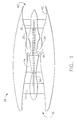
- Fig. 1 is a schematic of a gas turbine engine 20 including a fan 22, a high pressure compressor 24, and a combustor 26.
- the engine 20 also includes a high pressure turbine 28 and a low pressure turbine 30.
- the fan 22 and the turbine 30 are coupled by a first shaft 34, and the high pressure compressor 24 and the turbine 28 are coupled by a second shaft 36.
- the engine 20 is a F414 engine commercially available from GE Aircraft Engines, Evendale, Ohio.
- air received through an inlet end 38 of the engine 20 is compressed by the fan 22 and channeled to the high pressure compressor 24, wherein the compressed air is compressed even further.
- the highly compressed air from the high pressure compressor 22 is channeled to the combustor 26, wherein it is mixed with a fuel and ignited to produce combustion gases.
- the combustion gases are channeled from the combustor 26 to drive the turbines 28 and 30, and exit an outlet end 40 of the engine 20 through an exhaust nozzle assembly 42 to provide thrust.
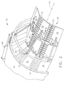
- Fig. 2 is a perspective of a portion of the gas turbine engine 20 illustrating a sector of the exhaust nozzle assembly 42.
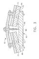
- Fig. 3 is a cross section of the exhaust nozzle assembly 42 taken along line 3-3 of Fig. 2.
- the nozzle assembly 42 includes a plurality of flaps 70 and a plurality of flap seals 72.
- the flaps 70 and the flap seals 72 are arranged circumferentially around a centerline 74 of the exhaust nozzle assembly 42.
- Each flap seal 72 is positioned between a pair of adjacent flaps 70 and radially inwardly with respect to the flaps 70, such that a portion of each flap seal 72 overlaps a portion of each adjacent flap 70.
- each flap 70 includes a body 76 having a sealing surface 78
- each flap seal 72 includes a body, generally referred to by the reference numeral 80, having a sealing surface 82.
- the flap seals 72 overlap adjacent flaps 70 such that during operation of the engine 20 a portion of each flap sealing surface 78 contacts a portion of each corresponding sealing surface 82 generally along an axial length of the flaps 70 and the flap seals 72.
- the flap seal bodies 80 are fabricated from a ceramic matrix composite material.
- the flap seal bodies 80 are fabricated from an oxide-based ceramic matrix composite material.
- the flap bodies 76 are fabricated from a ceramic matrix composite material.
- Respective radially inner surfaces 86 and 88 of the flaps 70 and the flap seals 72 form a generally continuous interior surface defining an exhaust nozzle orifice 90.
- the orifice 90 directs a flowpath of gases received from the turbine 30 (shown in Fig. 1) out of the engine outlet end 40 to produce thrust.
- the exhaust nozzle assembly 42 is a variable geometry exhaust nozzle, wherein a cross-sectional area of the nozzle orifice 90 is adjustable.
- a mounting assembly generally referred to herein with the reference numeral 92, couples each flap seal 72 to adjacent flaps 70.
- the assembly 92 is movably coupled to an outer casing 94 of the engine 20 to facilitate adjustment of the cross-sectional area of the orifice 90.
- the assembly 92 allows relative motion between the flaps 70 and the flap seals 72 to facilitate contact between the sealing surfaces 78 and respective sealing surfaces 82, and to facilitate adjustment of the cross-sectional area of the orifice 90.
- the exhaust nozzle orifice 90 is generally annular, however, it should be understood the orifice 90 may be any suitable shape.
- the exhaust nozzle orifice 90 is generally rectangular.
- a pressure of the flowpath gases exiting through the exhaust nozzle orifice 90 urges the flap seals 72 against the flaps 70, and more specifically, urges the sealing surfaces 82 of the seals 72 in contact with respective sealing surfaces 78 of the flaps 70.
- contact between the sealing surfaces 78 and respective sealing surfaces 82 substantially prevents leakage of gases between the flaps 70 and the flap seals 72.
- Fig. 4 is a perspective of an exemplary flap seal body 80 for use with the exhaust nozzle assembly 42 (shown in Figure 2).
- the body 80 includes a plurality of ends 100, 102, 104, and 106.
- the body 80 also includes the sealing surface 82, the radially inner surface 88, and a plurality of other surfaces 120, 122, 124, and 126. Any of the surfaces 82, 88, 120, 122, 124, and 126 may be designated a first surface or a second surface.
- the body 80 also includes plurality of openings, generally referred to by the reference numeral 128, for attachment to the mounting assembly 92.
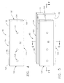
- Fig. 5 is a perspective of the flap seal body 80 after a material removal process.
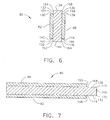
- Fig. 6 is a cross-section of the flap seal body 80 taken along line 6-6 of Fig. 5.
- Fig. 7 is a cross-section of the flap seal body 80 taken along line 7-7 of Fig. 5.
- Material is removed from the body 80 using any suitable machining process, such as, for example, cutting, grinding, planing, facing, and/or milling.
- the body 80 generally includes the ends 100, 102, 104, and 106, the sealing surface 82, the radially inner surface 88, and a plurality of mating surfaces 130, 132, 134, 136, 138, 140, 142, 144, 146, 148, and 150.
- the mating surfaces 130, 134, 138, 140, 142, and 144 are generally perpendicular to the surfaces 132 and 136.
- the mating surfaces 132 and 136 are generally perpendicular to the surfaces 146, 148, and 150. Any of the surfaces 82, 88, 130, 132, 134, 136, 138, 140, 142, 144, 146, 148, and 150 may be designated a first surface or a second surface.
- a plurality of edges 152, 154, 156, 158, 160, 162, 164, 166, 168, 170, 172, and 174 extend between corresponding surfaces 130, 132, 134, 136, 138, 140, 142, 144, 146, 148, and 150 of the body 80. More specifically, the edge 152 is defined at the intersection of the surfaces 130 and 132, the edge 154 is defined at the intersection of the surfaces 132 and 134, the edge 156 is defined at the intersection of the surfaces 134 and 136, and the edge 158 is defined at the intersection of the surfaces 136 and 138.
- the edge 160 is defined at the intersection of the surfaces 140 and 132
- the edge 162 is defined at the intersection of the surfaces 132 and 142
- the edge 164 is defined at the intersection of the surfaces 142 and 136
- the edge 166 is defined at the intersection of the surfaces 136 and 144.
- the edge 168 is defined at the intersection of the surfaces 150 and 136
- the edge 170 is defined at the intersection of the surfaces 136 and 148
- the edge 172 is defined at the intersection of the surfaces 148 and 132
- the edge 174 is defined at the intersection of the surfaces 132 and 146.
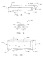
- Fig. 8 is a perspective of an exemplary cover, generally referred to by the reference numeral 180, for use with the flap seal body 80 (shown in Figure 5).
- Fig. 9 is a cross-section of the cover 180 taken along line 9-9 of Fig. 8.
- the cover 180 includes a plurality of outer sides 182, 184, and 186, and a plurality of mating sides 188, 190, 192, 194, and 196.
- the cover 180 also includes end surfaces 198 and 200 generally defining respective ends, generally referred to by the reference numerals 202 and 204, of the cover 180.
- the outer sides 182 and 186 are generally perpendicular to the outer side 184
- the mating sides 188 and 192 are generally perpendicular to the mating sides 190, 194, and 196.
- the cover 180 has a predetermined durability that is greater than a predetermined durability of a portion of the flap seal body 80 adjacent one or more of the flap seal body ends 100, 102, 104, and 106.
- the flap seal body 80 has a substantially uniform durability throughout that is less than the predetermined durability of the cover 180.
- the cover 180 is a metallic wire mesh, however, it should be understood that the cover 180 may be any material, and may be fabricated in any material configuration, having a durability greater than a predetermined durability of a portion of the flap seal body 80, and more specifically, a portion of the flap seal body 80 that includes the cover 180 bonded thereto, as described below.
- the cover 180 is a metallic wire mesh fabricated from a nickel-based alloy, such as, for example, HAYNES® HASTELLOY XTM alloy, commercially available from Haynes International, Inc., Kokomo, Indiana.
- the cover 180 is a metallic wire mesh fabricated from a cobalt-based alloy, such as, for example, HAYNES® alloy 188, commercially available from Haynes International, Inc., Kokomo, Indiana.
- the cover 180 is a metallic wire mesh fabricated from stainless steel, such as, for example, stainless steel grade 316 commercially available from Cleveland Wire Cloth, Cleveland, Ohio.
- Fig. 10 is a perspective view of the flap seal body 80 having a plurality of the covers 180 bonded thereto to increase a durability of the seal body 80 generally adjacent the ends 102, 104, and 106.
- a plurality of the covers 180 are bonded to the seal body 80.
- the seal body 80 may have any number of the covers 180 bonded thereto.
- the body 80 has only one cover 180 bonded thereto.
- the body 80 includes a plurality of the covers 180 that are each bonded to the seal body 80 adjacent a corresponding end 102, 104, and 106.
- the seal body 80 may include a cover 180 bonded thereto adjacent the body end 100.
- the covers 180 are bonded to the seal body 80 using an adhesive.
- the adhesive used to bond the covers 180a, 180b, and 180c to the seal body 80 is a ceramic adhesive, for example, a ceramic adhesive produced by combining a glass powder, for example, SP921® glass powder from Specialty Glass, Florida, and an alumina powder with a silica yielding polymer.
- a ceramic adhesive is Cotronics 901® adhesive, available from Cotronics Corporation, Brooklyn, NY.
- the seal body mating surfaces 130, 132, 134, 136, 138, 140, 142, 144, 146, 148, and 150 are cleaned by slightly sanding the surfaces and applying a solvent, for example acetone or isopropanol, to provide a substantially wetable surface that facilitates adhesion between the adhesive and the mating surfaces.
- a solvent for example acetone or isopropanol
- each cover 180a, 180b, and 180c After cleaning, the adhesive is applied to some or all of the mating sides 188, 190, 192, 194, and 196 of each cover 180a, 180b, and 180c, in addition to the seal body mating surfaces 130, 132, 134, 136, 138, 140, 142, 144, 146, 148, and 150.
- the covers 180a, 180b, and 180c are then positioned on the seal body 80 over the respective ends 102, 104, and 106, as illustrated in Fig. 10.
- the cover 180a is positioned over the end 102 such that the mating sides 188, 190, 192, 194, and 196 of the cover 180a contact the respective mating surfaces 132, 148, 136, 150, and 146 of the body 80, and accordingly, the cover 180a overlaps the seal body edges 168, 170, 172, and 174.
- the cover 180b is positioned over the end 104 such that the mating sides 188, 190, 192, 194, and 196 of the cover 180b contact the respective mating surfaces 132, 134, 136, 138, and 130 of the body 80, and accordingly, the cover 180b overlaps the seal body edges 152, 154, 156, and 158.
- the cover 180c is positioned over the end 106 such that the mating sides 188, 190, 192, 194, and 196 of the cover 180c contact the respective mating surfaces 136, 142, 132, 140, and 144 of the body 80, and accordingly, the cover 180c overlaps the seal body edges 160, 162, 164, and 166. Once dry, the adhesive bonds the covers 180 to the seal body 80.
- the greater durability of the covers 180 with respect to the body 80 facilitates increasing the durability of the seal body ends 102, 104, and 106 by reinforcing the body 80 adjacent the ends 102, 104, and 106.
- the covers 180a, 180b, and 180c each substantially overlap the respective ends 102, 104, and 106. However, it will be understood that the covers 180a, 180b, and 180c may each overlap only a portion of the respective ends 102, 104, and 106. Additionally, in the exemplary embodiment, the covers 180a, 180b, and 180c each substantially overlap the respective edges 168, 170, 172, 174, 152, 154, 156, 158, 160, 162, 164, and 166.
- covers 180a, 180b, and 180c may each overlap only a portion of the respective edges 168, 170, 172, 174, 152, 154, 156, 158, 160, 162, 164, and 166.
- seal body 80 is herein described and illustrated in the exemplary manner, it should be understood that the seal body 80 may include any number of covers 180 each bonded to any portion of the body 80 such that at least one cover 180 overlaps at least a portion of the body 80.
- the above-described cover is cost-effective and reliable for increasing a durability of a ceramic matrix composite material. More specifically, the cover facilitates reinforcing a portion of the ceramic matrix composite material. As a result, the cover may increase the performance and useful life of the ceramic matrix composite material, and thereby reduce replacement costs. Additionally, the cover may increase a wear resistance and a strain to failure ratio of the ceramic matrix composite material, and may allow the ceramic matrix composite material to experience higher thermal gradients without failing. In the exemplary embodiment, the cover facilitates increasing the performance and useful life of a gas turbine engine exhaust seal. As a result, the exemplary cover facilitates reducing a number of exhaust nozzle seals that are replaced within a gas turbine engine to maintain a desired operational efficiency of the engine.
- gas turbine engine exhaust nozzle assemblies are described above in detail.
- the assemblies are not limited to the specific embodiments described herein, but rather, components of each assembly may be utilized independently and separately from other components described herein.
- Each exhaust nozzle assembly component can also be used in combination with other exhaust nozzle assembly components.
Landscapes
- Engineering & Computer Science (AREA)
- Chemical & Material Sciences (AREA)
- Combustion & Propulsion (AREA)
- Mechanical Engineering (AREA)
- General Engineering & Computer Science (AREA)
- Turbine Rotor Nozzle Sealing (AREA)
- Gasket Seals (AREA)
- Ceramic Products (AREA)
Applications Claiming Priority (2)
| Application Number | Priority Date | Filing Date | Title |
|---|---|---|---|
| US10/703,273 US20050097893A1 (en) | 2003-11-07 | 2003-11-07 | Method and apparatus for increasing a durability of a body |
| US703273 | 2003-11-07 |
Publications (1)
| Publication Number | Publication Date |
|---|---|
| EP1529949A1 true EP1529949A1 (en) | 2005-05-11 |
Family
ID=34435568
Family Applications (1)
| Application Number | Title | Priority Date | Filing Date |
|---|---|---|---|
| EP20040256837 Withdrawn EP1529949A1 (en) | 2003-11-07 | 2004-11-04 | Method and apparatus for increasing a durability of an exhaust nozzle flap seal |
Country Status (4)
| Country | Link |
|---|---|
| US (2) | US20050097893A1 (cg-RX-API-DMAC7.html) |
| EP (1) | EP1529949A1 (cg-RX-API-DMAC7.html) |
| JP (1) | JP2005140116A (cg-RX-API-DMAC7.html) |
| CA (1) | CA2486014A1 (cg-RX-API-DMAC7.html) |
Families Citing this family (7)
| Publication number | Priority date | Publication date | Assignee | Title |
|---|---|---|---|---|
| US8047004B2 (en) * | 2008-02-12 | 2011-11-01 | The Boeing Company | Stave and ring CMC nozzle |
| US9840984B2 (en) * | 2013-08-20 | 2017-12-12 | United Technologies Corporation | Linkage to control and restrain flap movement |
| US10451001B2 (en) | 2014-12-09 | 2019-10-22 | Rolls-Royce Corporation | CMC oxide-oxide mixer design |
| US20170159565A1 (en) * | 2015-12-04 | 2017-06-08 | Jetoptera, Inc. | Micro-turbine gas generator and propulsive system |
| US10808576B2 (en) * | 2017-02-06 | 2020-10-20 | General Electric Company | Methods of replacing seals in exhaust frames of turbine systems and related components |
| WO2022140040A2 (en) * | 2020-12-03 | 2022-06-30 | The Government Of The United States Of America, As Represented By The Secretary Of The Navy | Methods and apparatuses for reducing engine noise |
| CN114991991B (zh) * | 2022-05-30 | 2024-04-02 | 中国航发四川燃气涡轮研究院 | 具有冷气可调功能的加力防振隔热屏 |
Citations (10)
| Publication number | Priority date | Publication date | Assignee | Title |
|---|---|---|---|---|
| WO1983000715A1 (en) * | 1981-08-14 | 1983-03-03 | Hastings, Otis, H. | Insulating apparatus and composite laminates employed therein |
| US4441726A (en) * | 1981-12-14 | 1984-04-10 | Shan-Rod, Inc. | Heat and vibration resistant seal |
| EP0366484A2 (en) * | 1988-10-28 | 1990-05-02 | Minnesota Mining And Manufacturing Company | Erosion resistant mounting composite for catalytic converter |
| US4936064A (en) * | 1989-02-16 | 1990-06-26 | Backer Rod Manufacturing And Supply Company | Fireproof panel |
| US5125557A (en) * | 1983-09-30 | 1992-06-30 | Kabushiki Kaisha Toshiba | Ceramics bonded product and method of producing the same |
| US5584173A (en) * | 1993-04-05 | 1996-12-17 | General Electric Company | Nozzle seal assembly with removable baseplate |
| US5686039A (en) * | 1995-06-30 | 1997-11-11 | Minnesota Mining And Manufacturing Company | Methods of making a catalytic converter or diesel particulate filter |
| US6143107A (en) * | 1996-10-31 | 2000-11-07 | Hounsel; Mack A. | Hard-faced insulating refractory fiber linings |
| EP1126221A1 (de) * | 2000-02-17 | 2001-08-22 | Siemens Aktiengesellschaft | Gepolsterter Hitzeschildstein zur Auskleidung einer Gasturbinenbrennkammerwand |
| US6280584B1 (en) * | 1998-07-29 | 2001-08-28 | Applied Materials, Inc. | Compliant bond structure for joining ceramic to metal |
Family Cites Families (14)
| Publication number | Priority date | Publication date | Assignee | Title |
|---|---|---|---|---|
| US4780432A (en) * | 1986-09-02 | 1988-10-25 | United Technologies Corporation | Controlled fiber distribution technique for glass matrix composites |
| US4837230A (en) * | 1987-05-07 | 1989-06-06 | Kaiser Aerotech | Structural ceramic materials having refractory interface layers |
| US4994416A (en) * | 1988-02-04 | 1991-02-19 | Martin Marietta Energy Systems, Inc. | Ceramic composites reinforced with modified silicon carbide whiskers and method for modifying the whiskers |
| US4916092A (en) * | 1988-02-04 | 1990-04-10 | Martin Marietta Energy Systems, Inc. | Ceramic composites reinforced with modified silicon carbide whiskers |
| US5137852A (en) * | 1991-01-11 | 1992-08-11 | Rockwell International Corp. | High temperature ceramic composites |
| US6338906B1 (en) * | 1992-09-17 | 2002-01-15 | Coorstek, Inc. | Metal-infiltrated ceramic seal |
| CA2137528C (en) * | 1994-04-15 | 2001-07-03 | Peter E. D. Morgan | Ceramic composites having a weak bond interphase material selected from monazites and xenotimes |
| US5839663A (en) * | 1996-07-23 | 1998-11-24 | United Technologies Corporation | Gas turbine exhaust nozzle flap and flap seal apparatus |
| US6528190B1 (en) * | 2000-08-02 | 2003-03-04 | Siemens Westinghouse Power Corporation | Fiber coating compounds for reinforced ceramic matrix composites |
| US6471469B2 (en) * | 2000-11-30 | 2002-10-29 | General Electric Company | Methods and apparatus for sealing gas turbine engine variable nozzles |
| US7291407B2 (en) * | 2002-09-06 | 2007-11-06 | Siemens Power Generation, Inc. | Ceramic material having ceramic matrix composite backing and method of manufacturing |
| US20040242095A1 (en) * | 2003-05-27 | 2004-12-02 | Amit Prakash | Composites reinforced by wire net or mesh for lightweight, strength and stiffness |
| US7282274B2 (en) * | 2003-11-07 | 2007-10-16 | General Electric Company | Integral composite structural material |
| US7310949B2 (en) * | 2003-11-07 | 2007-12-25 | General Electric Company | Method and apparatus for arresting a crack within a body |
-
2003
- 2003-11-07 US US10/703,273 patent/US20050097893A1/en not_active Abandoned
-
2004
- 2004-10-28 CA CA 2486014 patent/CA2486014A1/en not_active Abandoned
- 2004-11-04 EP EP20040256837 patent/EP1529949A1/en not_active Withdrawn
- 2004-11-05 JP JP2004321704A patent/JP2005140116A/ja not_active Withdrawn
-
2006
- 2006-04-19 US US11/406,892 patent/US20070117480A1/en not_active Abandoned
Patent Citations (10)
| Publication number | Priority date | Publication date | Assignee | Title |
|---|---|---|---|---|
| WO1983000715A1 (en) * | 1981-08-14 | 1983-03-03 | Hastings, Otis, H. | Insulating apparatus and composite laminates employed therein |
| US4441726A (en) * | 1981-12-14 | 1984-04-10 | Shan-Rod, Inc. | Heat and vibration resistant seal |
| US5125557A (en) * | 1983-09-30 | 1992-06-30 | Kabushiki Kaisha Toshiba | Ceramics bonded product and method of producing the same |
| EP0366484A2 (en) * | 1988-10-28 | 1990-05-02 | Minnesota Mining And Manufacturing Company | Erosion resistant mounting composite for catalytic converter |
| US4936064A (en) * | 1989-02-16 | 1990-06-26 | Backer Rod Manufacturing And Supply Company | Fireproof panel |
| US5584173A (en) * | 1993-04-05 | 1996-12-17 | General Electric Company | Nozzle seal assembly with removable baseplate |
| US5686039A (en) * | 1995-06-30 | 1997-11-11 | Minnesota Mining And Manufacturing Company | Methods of making a catalytic converter or diesel particulate filter |
| US6143107A (en) * | 1996-10-31 | 2000-11-07 | Hounsel; Mack A. | Hard-faced insulating refractory fiber linings |
| US6280584B1 (en) * | 1998-07-29 | 2001-08-28 | Applied Materials, Inc. | Compliant bond structure for joining ceramic to metal |
| EP1126221A1 (de) * | 2000-02-17 | 2001-08-22 | Siemens Aktiengesellschaft | Gepolsterter Hitzeschildstein zur Auskleidung einer Gasturbinenbrennkammerwand |
Also Published As
| Publication number | Publication date |
|---|---|
| JP2005140116A (ja) | 2005-06-02 |
| CA2486014A1 (en) | 2005-05-07 |
| US20050097893A1 (en) | 2005-05-12 |
| US20070117480A1 (en) | 2007-05-24 |
Similar Documents
| Publication | Publication Date | Title |
|---|---|---|
| US11181006B2 (en) | Turbine tip shroud assembly with plural shroud segments having inter-segment seal arrangement | |
| CA2509743C (en) | Turbine vane collar seal | |
| EP3323985B1 (en) | Airfoil, gas turbine engine article, corresponding gas turbine engine and method of assembling an airfoil | |
| EP3543468A1 (en) | Turbine tip shroud assembly with plural shroud segments having inter-segment seal arrangement | |
| US11913645B2 (en) | Combustor assembly for a turbine engine | |
| CA2486237C (en) | Method and apparatus for arresting a crack within a body | |
| EP1892381A2 (en) | Sealing arrangement | |
| EP3486433B1 (en) | Labyrinth seal with different tooth heights | |
| EP1529949A1 (en) | Method and apparatus for increasing a durability of an exhaust nozzle flap seal | |
| EP3323994B1 (en) | Airfoil with seal between endwall and airfoil section | |
| EP3323999A1 (en) | Endwall arc segments with cover across joint | |
| EP2312186A1 (en) | Method of manufacturing a fairing with an integrated seal | |
| CA2486024C (en) | Method and apparatus for arresting a crack within a body | |
| US11796176B2 (en) | Combustor assembly for a turbine engine | |
| US10544699B2 (en) | System and method for minimizing the turbine blade to vane platform overlap gap | |
| US10982855B2 (en) | Combustor cap assembly with cooling microchannels | |
| US12031442B2 (en) | Turbine engine with a floating interstage seal | |
| EP2312125A1 (en) | Fairing seal | |
| CA2682818A1 (en) | Method of manufacturing a fairing with an integrated seal |
Legal Events
| Date | Code | Title | Description |
|---|---|---|---|
| PUAI | Public reference made under article 153(3) epc to a published international application that has entered the european phase |
Free format text: ORIGINAL CODE: 0009012 |
|
| AK | Designated contracting states |
Kind code of ref document: A1 Designated state(s): AT BE BG CH CY CZ DE DK EE ES FI FR GB GR HU IE IS IT LI LU MC NL PL PT RO SE SI SK TR |
|
| AX | Request for extension of the european patent |
Extension state: AL HR LT LV MK YU |
|
| 17P | Request for examination filed |
Effective date: 20051111 |
|
| AKX | Designation fees paid |
Designated state(s): DE FR GB IT SE |
|
| 17Q | First examination report despatched |
Effective date: 20071228 |
|
| STAA | Information on the status of an ep patent application or granted ep patent |
Free format text: STATUS: THE APPLICATION IS DEEMED TO BE WITHDRAWN |
|
| 18D | Application deemed to be withdrawn |
Effective date: 20080708 |