EP1529836B1 - Chambre de traitement de cellules - Google Patents
Chambre de traitement de cellules Download PDFInfo
- Publication number
- EP1529836B1 EP1529836B1 EP04025370A EP04025370A EP1529836B1 EP 1529836 B1 EP1529836 B1 EP 1529836B1 EP 04025370 A EP04025370 A EP 04025370A EP 04025370 A EP04025370 A EP 04025370A EP 1529836 B1 EP1529836 B1 EP 1529836B1
- Authority
- EP
- European Patent Office
- Prior art keywords
- core
- chamber according
- electrodes
- wires
- beaker
- Prior art date
- Legal status (The legal status is an assumption and is not a legal conclusion. Google has not performed a legal analysis and makes no representation as to the accuracy of the status listed.)
- Expired - Lifetime
Links
Images

Classifications
-
- C—CHEMISTRY; METALLURGY
- C12—BIOCHEMISTRY; BEER; SPIRITS; WINE; VINEGAR; MICROBIOLOGY; ENZYMOLOGY; MUTATION OR GENETIC ENGINEERING
- C12M—APPARATUS FOR ENZYMOLOGY OR MICROBIOLOGY; APPARATUS FOR CULTURING MICROORGANISMS FOR PRODUCING BIOMASS, FOR GROWING CELLS OR FOR OBTAINING FERMENTATION OR METABOLIC PRODUCTS, i.e. BIOREACTORS OR FERMENTERS
- C12M35/00—Means for application of stress for stimulating the growth of microorganisms or the generation of fermentation or metabolic products; Means for electroporation or cell fusion
- C12M35/02—Electrical or electromagnetic means, e.g. for electroporation or for cell fusion
Definitions
- the invention relates to a chamber for treating cells contained in a suspension in the electric field.
- the chamber according to the invention serves e.g. the electrofusion of cells.
- electrofusion at least two cells are fused in an electric field that is established between two electrodes.
- the electrofusion can e.g. in three steps.
- a first step pre-alignment
- the cells are aligned by applying a high-frequency AC voltage and brought into contact with each other.
- a second step pulse
- the cell membranes are broken up by means of a short, strong current pulse.
- post-alignment the broken cells are fused by re-applying a high-frequency AC voltage to allow an automatic fusion.
- Cell fusion chambers are known in which a pair of helical grooves on a conical body of non-conductive plastic, two thin platinum wires are wound in parallel, forming the electrodes. Furthermore, the cell fusion chambers have a conical cup into which the plastic body can be screwed. The plastic body has a head projecting beyond the top of the cup, on which a plug is mounted, which is connected to the electrodes. The high-frequency AC voltage can be supplied via the plug.
- the preparation of the cell fusion chambers is complicated and expensive, so that a multiple use of the cell fusion chambers is economically desirable. For this, the cell fusion chambers between different applications have to be cleaned mechanically and with cleaning agents.
- the known cell fusion chambers are not autoclavable or sterilizable, since they are usually no longer functional after appropriate treatment.
- the US-A-4,764,473 discloses a cell treatment chamber having two thin platinum wires on a cylindrical body of polymethacrylate (PMMA). This cell fusion chamber is usually no longer functional after autoclaving or sterilization.
- PMMA polymethacrylate
- the object of the invention is to provide a cell fusion chamber which is autoclavable and / or sterilizable.
- the adjustment has been made so far that the electrodes maintain their position relative to the core over the entire temperature range from ambient (about -21 to +35 ° C) to the typical autoclaving and / or sterilizing temperatures (about +120 to +180 ° C). essentially retained.
- the electrodes essentially maintain their position relative to the core if they do not shift so far that a short circuit occurs.
- the thermal expansion coefficients of the material of the electrodes and of the material of the core are adjusted to one another such that the electrodes reach their position with respect to the core up to the temperatures reached in steam sterilization and / or radiation sterilization (about +120 to + 140 ° C.) do not change significantly.
- the core is cylindrical or conical and / or the cup outside and / or inside cylindrical and / or conical.
- the production of the electrodes is favored by winding wires.
- the space has a uniform depth, which in turn is beneficial for uniform treatment of the cells in the suspension.
- the electrodes are wires that are wound in a multi-threaded helical or ramped manner onto the core.
- the helical course is e.g. in a cylindrical or conical and the ramp-shaped course, e.g. given at a polyhedral core.
- the core has a plurality of helically or ramp-shaped grooves or grooves on the outer side, in which the wires are guided. This additionally prevents slippage of the wires, which could occur due to little remaining differences in the thermal expansion coefficient or due to mechanical action on the wires.
- the wires have angled ends which are inserted in radial bores of the core. As a result, the wires are securely fixed on the core.
- the radial bores also allow the wires to be connected to an HF voltage generator.
- the angled wire ends are fixed in the radial bores by means of a non-cytotoxic adhesive. It is understood that the adhesive is stable in the temperature range in which the chamber is usable.
- the electrodes are arranged on the core conductor tracks.
- the conductor tracks can be produced, for example, by surface coating of the core with an electrically conductive material, partial covering of the areas provided as conductor tracks, and chemical detachment of the uncovered areas of the coating.
- a bonding agent is arranged between the core and the conductor tracks, which reinforces the adhesion of the material of the conductor tracks to the material of the core.
- the tracks run e.g. also more or less helical or parallel to the longitudinal axis of the core.
- the tracks have an interdigital structure, i. comb-like, interlocking areas.
- the core can be fixed in various ways with respect to the cup.
- a fixation takes place directly on the cup.
- the core above the electrodes has an external thread and the cup below an opening has an internal thread for screwing in the external thread.
- the core is then simply screwed into the cup at the end of an axial insertion movement.
- the core has a head above the electrodes.
- the head is usable for handling the core, whereby a contamination of the electrodes is avoidable.
- the head is formed on the circumference in a manner that promotes screwing into the cup.
- the core has a blind bore extending from the upper side, into which the electrodes are guided.
- the electrodes can be contacted by the blind hole from the outside to apply the RF voltage.
- the electrodes are connected to a plug at the top of the core.
- the electrodes are made of platinum.
- platinum is particularly suitable for the treatment of cells in a suspension.
- Both as wires and as printed conductors running electrodes are made of platinum.
- Platinum has a thermal expansion coefficient of 9.0 x 10 -6 1 / K.
- the core is made of glass ceramic.
- a glass-ceramic with a thermal expansion coefficient of 9.3 ⁇ 10 -6 1 / K is available Available.
- Particularly advantageous is the combination of electrodes made of platinum with a core of glass ceramic, since this connects the inert material of the electrodes with a complete approximation of the thermal expansion coefficient. This combination of materials achieves that the electrodes substantially maintain their position relative to the core throughout the temperature range from ambient to autoclaving and / or sterilizing temperatures. Platinum and glass ceramic are also radiation sterilizable.
- the core made of chipable glass ceramic is machined or injection molded from glass ceramic.
- a suitable spanbares material is offered under the product name MACOR ® from Corning.
- ceramic injection molding process ceramic is mixed in the powder state with polymeric matrix and processed into granules.
- an injection molding machine is fed, which supplies a green body. This is sintered to substantially drive off the organic phase and cake the ceramic articles.
- the cup of PC and / or the plug made of PEEK are radiation sterilizable.
- top and bottom is meant the location of elements of the chamber in a typical application situation where the cup is placed with the bottom on a ground and with the opening vertically above the bottom. Accordingly, the coaxially aligned with the cup core is arranged with the head and the plug vertically above the opening of the cup.
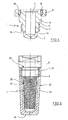
- a core 1 has a slightly conical support section 2, on which two parallel grooves 3, 4 run helically.
- the core 1 has a crowned lower end section 5.
- a threaded portion 6 which has a significantly larger diameter than the adjacent end of the section 2 and an external thread 7.
- the core 1 has a head 8, which is formed in the upper region into a rectangular plate 9. Head 8 and threaded portion 7 are separated by a recess 10 from each other.
- the core 1 has an outgoing from the upper end blind bore 11 which extends in the longitudinal direction of the core 1 into the region of the support section 2.
- the support portion 2 at the lower end two superimposed radial bores 12, 13, which are designed as blind holes.
- the core 1 has two diametrically opposed radial bores 14, 15, which open into the blind bore 11.
- the core 1 has four short axial threaded bores 16, 17, 18, 19.
- Electrodes in the form of wires made of platinum 20, 21 are wound in parallel on the support section 2 and guided with their ends into the radial bores 12, 13 and 14, 15. In the radial bores, they are fixed by means of a suitable, non-cytotoxic adhesive. In the drawing, only two parallel turns of the platinum wires 20, 21 are registered. However, the platinum wires 20, 21 actually extend substantially over the entire length of the grooves 3, 4.
- a - not shown - plug is arranged on the head 8 of the core 1 and there bolted to the threaded holes 16, 17, 18, 19 of the plate 9.
- the plug is electrically connected to the upper ends of the wires 20, 21.
- the electrodes 20, 21 thus consist of platinum wire.
- the core 1 is made of glass ceramic MACOR ® Corning machined.
- the plug is made of PEEK.
- an associated cup 22 has an inner and outer conical jacket 23 whose cone angle corresponds to that of the support portion 2 of the core 1. Further, the cup 22 has a bottom 24 with a flat bottom and this opposite the upper end of an opening 25. Below the opening 25, an internal thread 26 is present.
- the cup 22 is made of PC.
- core 1 and beaker 22 are first autoclaved or steam or radiation sterilized. Due to the used materials this is possible without affecting the functioning of the chamber 1, 22.
- the suspension is filled into the cup 22 and finally the core 1 is axially inserted and screwed.
- the suspension then fills the space 27 between the core 1 and cup 22.
- an RF voltage generator is connected to the plug and the treatment of the cells is performed.
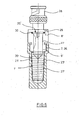
- Fig. 6 are the with the embodiment of Fig. 1 to 5 substantially coincident features denoted by the same reference numerals but which is provided with a paint.
- the core 1 ' has a plug 28 which is fixed at the top of the head 8'.
- the plug 28 has a mounting plate 29 which is screwed to the top of the head 8 ', wherein a sealing ring 30 is interposed.
- the platinum wires 20 ', 21' are connected within the blind bore 11 'with contacts of the plug 28.
- the cup 23 ' is internally conical corresponding to the cone of the core 1'. Outside, the cup 23 'is cylindrical.
Landscapes
- Health & Medical Sciences (AREA)
- Life Sciences & Earth Sciences (AREA)
- Engineering & Computer Science (AREA)
- Wood Science & Technology (AREA)
- Organic Chemistry (AREA)
- Biotechnology (AREA)
- Chemical & Material Sciences (AREA)
- Genetics & Genomics (AREA)
- Bioinformatics & Cheminformatics (AREA)
- Zoology (AREA)
- Microbiology (AREA)
- Sustainable Development (AREA)
- Physics & Mathematics (AREA)
- Biomedical Technology (AREA)
- Cell Biology (AREA)
- Biochemistry (AREA)
- General Engineering & Computer Science (AREA)
- General Health & Medical Sciences (AREA)
- Electromagnetism (AREA)
- Apparatus For Disinfection Or Sterilisation (AREA)
- Physical Or Chemical Processes And Apparatus (AREA)
- Apparatus Associated With Microorganisms And Enzymes (AREA)
Claims (19)
- Chambre de traitement de cellules contenues dans une suspension, dans un champ électrique, comportant- un bécher (22) en matériau non électroconducteur, dans lequel un noyau (1) allongé en matériau non électroconducteur est introduit au moins partiellement dans le sens axial à travers une ouverture (25), un espace (27) pour la réception de la suspension étant formé entre le bécher (22) et le noyau (1),- au moins deux électrodes (20, 21) en matériau électroconducteur, qui sont disposées sur la face extérieure du noyau (1), orientée vers l'espace (27), entre lesquelles, un champ électrique pour le traitement de cellules dans une suspension contenue dans l'espace (27) peut être généré, moyennant l'application d'une tension,- les coefficients de dilatation thermique du matériau des électrodes (20, 21) et du matériau du noyau (1) étant adaptés entre eux de telle sorte que les électrodes (20, 21) ne changent pas nettement leur position par rapport au noyau dans le domaine des températures allant de la température ambiante jusqu'à des températures atteintes lors du traitement en autoclave et/ou lors de la stérilisation.
- Chambre selon la revendication 1, dans laquelle les coefficients de dilatation thermique du matériau des électrodes (20, 21) et du matériau du noyau (1) sont adaptés entre eux de telle sorte que les électrodes (20, 21) ne changent pas nettement leur position par rapport au noyau (1) jusqu'à des températures atteintes lors de la stérilisation par vapeur et/ou par rayonnement.
- Chambre selon la revendication 1 ou 2, dans laquelle le noyau (1) est cylindrique ou conique et/ou le bécher (22) est cylindrique et/ou conique à l'extérieur et/ou à l'intérieur.
- Chambre selon l'une quelconque des revendications 1 à 3, dans laquelle les électrodes (20, 21) sont des fils, qui sont enroulés sur le noyau (1) en plusieurs pas en forme de spirale ou en forme de rampe.
- Chambre selon la revendication 4, dans laquelle le noyau (1) comporte, sur la face extérieure, plusieurs cannelures (3, 4) ou rainures parallèles, qui s'étendent en forme de spirale ou en forme de rampe et dans lesquelles sont guidés les fils (20, 21).
- Chambre selon la revendication 4 ou 5, dans laquelle les fils (20, 21) comportent des extrémités pliées, qui sont insérées dans des forures radiales (12, 13, 14, 15) du noyau (1).
- Chambre selon la revendication 6, dans laquelle les extrémités pliées sont fixées dans la forure radiale (12, 13, 14, 15) au moyen d'une colle non cytotoxique.
- Chambre selon l'une quelconque des revendications 1 à 3, dans laquelle les électrodes (20, 21) sont des bandes conductrices disposées sur le noyau (1).
- Chambre selon la revendication 8, dans laquelle un agent adhésif est disposé entre le noyau (1) et les bandes conductrices.
- Chambre selon la revendication 1 ou 9, dans laquelle les bandes conductrices comportent une structure interdigitale.
- Chambre selon l'une quelconque des revendications 1 à 10, dans laquelle le noyau (1) comporte un filetage extérieur (7) au-dessus des électrodes (20, 21) et le bécher (22) comporte, en dessous d'une ouverture (25), un filetage intérieur (26) pour le vissage du filetage extérieur (7).
- Chambre selon l'une quelconque des revendications 1 à 11, dans laquelle le noyau (1) possède une tête (8) au-dessus des électrodes (20, 21).
- Chambre selon l'une quelconque des revendications 1 à 12, laquelle comporte un trou borgne (11) axial, qui s'étend depuis l'extrémité supérieure du noyau (1) à peu près jusqu'au niveau des électrodes (20, 21).
- Chambre selon l'une quelconque des revendications 1 à 13, dans laquelle les électrodes (20, 21) sont reliés par un connecteur enfichable (28) à la face supérieure du noyau (1).
- Chambre selon l'une quelconque des revendications 1 à 14, dans laquelle les électrodes (20, 21) sont en platine.
- Chambre selon l'une quelconque des revendications 1 à 15, dans laquelle le noyau (1) est en vitrocéramique.
- Chambre selon l'une quelconque des revendications 1 à 16, avec un noyau (1) formé par enlèvement de copeaux dans une vitrocéramique usinable par enlèvement de copeaux ou moulé par injection en vitrocéramique.
- Chambre selon l'une quelconque des revendications 1 à 17, avec un bécher (22) en PC.
- Chambre selon l'une quelconque des revendications 14 à 18, avec un connecteur enfichable (28) en PEEK.
Applications Claiming Priority (2)
| Application Number | Priority Date | Filing Date | Title |
|---|---|---|---|
| DE10351833A DE10351833B4 (de) | 2003-11-06 | 2003-11-06 | Zellbehandlungskammer |
| DE10351833 | 2003-11-06 |
Publications (2)
| Publication Number | Publication Date |
|---|---|
| EP1529836A1 EP1529836A1 (fr) | 2005-05-11 |
| EP1529836B1 true EP1529836B1 (fr) | 2008-04-09 |
Family
ID=34306424
Family Applications (1)
| Application Number | Title | Priority Date | Filing Date |
|---|---|---|---|
| EP04025370A Expired - Lifetime EP1529836B1 (fr) | 2003-11-06 | 2004-10-26 | Chambre de traitement de cellules |
Country Status (4)
| Country | Link |
|---|---|
| US (1) | US7501277B2 (fr) |
| EP (1) | EP1529836B1 (fr) |
| JP (1) | JP4309330B2 (fr) |
| DE (2) | DE10351833B4 (fr) |
Family Cites Families (8)
| Publication number | Priority date | Publication date | Assignee | Title |
|---|---|---|---|---|
| DE3317415A1 (de) * | 1983-05-13 | 1984-11-15 | Kernforschungsanlage Jülich GmbH, 5170 Jülich | Kammer zur behandlung von zellen im elektrischen feld |
| DE8813314U1 (de) * | 1988-10-22 | 1989-01-12 | Erno Raumfahrttechnik Gmbh, 2800 Bremen | Vorrichtung zur Durchführung biologischer Experimente |
| US4921738A (en) * | 1988-12-09 | 1990-05-01 | The United States Of America As Represented By The United States Department Of Energy | Li2 O-Al2 O3 -SiO2 glass ceramic-aluminum containing austenitic stainless steel composite body and a method of producing the same |
| JPH08236654A (ja) * | 1995-02-23 | 1996-09-13 | Matsushita Electric Ind Co Ltd | チップキャリアとその製造方法 |
| US5874268A (en) * | 1996-09-23 | 1999-02-23 | Duke University | Method of introducing exogenous compounds into cells by electroporation and apparatus for same |
| DE19917571B4 (de) * | 1999-04-19 | 2014-03-20 | Robert Poppe | Elektrodenraster für Elektroporationsreaktionsansätze |
| DE10116211A1 (de) * | 2001-03-27 | 2002-10-10 | Eppendorf Ag | Kammer zur Behandlung von in einer Suspension enthaltenen Zellen im elektrischen Feld |
| DE10127247B4 (de) * | 2001-06-05 | 2006-12-07 | Eppendorf Ag | Vorrichtung und Verfahren zur elektrischen Behandlung suspendierter biologischer Partikel |
-
2003
- 2003-11-06 DE DE10351833A patent/DE10351833B4/de not_active Expired - Fee Related
-
2004
- 2004-10-26 DE DE502004006756T patent/DE502004006756D1/de not_active Expired - Lifetime
- 2004-10-26 EP EP04025370A patent/EP1529836B1/fr not_active Expired - Lifetime
- 2004-11-04 US US10/982,630 patent/US7501277B2/en not_active Expired - Fee Related
- 2004-11-05 JP JP2004322368A patent/JP4309330B2/ja not_active Expired - Fee Related
Also Published As
| Publication number | Publication date |
|---|---|
| JP4309330B2 (ja) | 2009-08-05 |
| EP1529836A1 (fr) | 2005-05-11 |
| DE10351833A1 (de) | 2005-06-16 |
| US7501277B2 (en) | 2009-03-10 |
| DE10351833B4 (de) | 2010-03-11 |
| DE502004006756D1 (de) | 2008-05-21 |
| US20050064580A1 (en) | 2005-03-24 |
| JP2005137371A (ja) | 2005-06-02 |
Similar Documents
| Publication | Publication Date | Title |
|---|---|---|
| EP1923094B1 (fr) | Cathéter à électrode destiné à des interventions | |
| DE69326080T2 (de) | Implantierbare elektrode | |
| EP1577378B1 (fr) | Récipient et installation destinée a creer des champs électriques dans des espaces de réaction independents | |
| EP3326436B1 (fr) | Ensemble d'électrodes et source de plasma pour générer un plasma non thermique ainsi que procédé de fonctionnement d'une source de plasma | |
| EP2635218B1 (fr) | Dispositif à électrodes d'un instrument d'électrochirurgie | |
| EP1062970B1 (fr) | Ensemble électrode | |
| WO2006116968A2 (fr) | Neuroelectrode biostable | |
| DE3211510A1 (de) | Implantierbare leitung | |
| EP2823856A1 (fr) | Composant de contact à ressort, douille de prise et composant de prise de contact | |
| EP3213376B1 (fr) | Connecteur implantable | |
| WO1999024109A2 (fr) | Electrode cuff et son procede de production | |
| DE102018221355B4 (de) | Kontaktierungsverfahren und System | |
| DE3518317A1 (de) | Elektrostimulations-elektrode | |
| EP1955729B1 (fr) | Ligne d'électrodes et élément de raccord pour un stimulateur cardiaque implantable | |
| DE3311507A1 (de) | Schnecken-prothesenanordnung und verfahren zum herstellen derselben | |
| EP1245669A1 (fr) | Enceinte pour le traitement de cellules contenues dans une suspension par un champ électrique | |
| EP1354610B1 (fr) | Fil d'électrode constitué d'un polymère électriquement conducteur | |
| DE10351833B4 (de) | Zellbehandlungskammer | |
| DE102010031259B4 (de) | Stützeinrichtung für eine Magnetronanordnung mit einem rotierenden Target | |
| DE102021102864B3 (de) | Federkontaktring | |
| EP2253181B1 (fr) | Broche de raccordement et raccordement électrique | |
| EP2283894B1 (fr) | Conduite d'électrodes de stimulation | |
| DE3424889A1 (de) | Elektrode fuer einen gasentladungsreaktor | |
| EP1722849A1 (fr) | Electrode de stimulation | |
| DE102008010188A1 (de) | Verfahren zur Herstellung eines Isolationsschlauchs und Verfahren zur Herstellung einer Elektrode |
Legal Events
| Date | Code | Title | Description |
|---|---|---|---|
| PUAI | Public reference made under article 153(3) epc to a published international application that has entered the european phase |
Free format text: ORIGINAL CODE: 0009012 |
|
| AK | Designated contracting states |
Kind code of ref document: A1 Designated state(s): AT BE BG CH CY CZ DE DK EE ES FI FR GB GR HU IE IT LI LU MC NL PL PT RO SE SI SK TR |
|
| AX | Request for extension of the european patent |
Extension state: AL HR LT LV MK |
|
| 17P | Request for examination filed |
Effective date: 20050416 |
|
| AKX | Designation fees paid |
Designated state(s): DE FR GB IT |
|
| 17Q | First examination report despatched |
Effective date: 20061005 |
|
| GRAP | Despatch of communication of intention to grant a patent |
Free format text: ORIGINAL CODE: EPIDOSNIGR1 |
|
| GRAS | Grant fee paid |
Free format text: ORIGINAL CODE: EPIDOSNIGR3 |
|
| GRAA | (expected) grant |
Free format text: ORIGINAL CODE: 0009210 |
|
| AK | Designated contracting states |
Kind code of ref document: B1 Designated state(s): DE FR GB IT |
|
| REG | Reference to a national code |
Ref country code: GB Ref legal event code: FG4D Free format text: NOT ENGLISH |
|
| GBT | Gb: translation of ep patent filed (gb section 77(6)(a)/1977) |
Effective date: 20080415 |
|
| REF | Corresponds to: |
Ref document number: 502004006756 Country of ref document: DE Date of ref document: 20080521 Kind code of ref document: P |
|
| ET | Fr: translation filed | ||
| PLBE | No opposition filed within time limit |
Free format text: ORIGINAL CODE: 0009261 |
|
| STAA | Information on the status of an ep patent application or granted ep patent |
Free format text: STATUS: NO OPPOSITION FILED WITHIN TIME LIMIT |
|
| 26N | No opposition filed |
Effective date: 20090112 |
|
| REG | Reference to a national code |
Ref country code: FR Ref legal event code: PLFP Year of fee payment: 12 |
|
| PGFP | Annual fee paid to national office [announced via postgrant information from national office to epo] |
Ref country code: DE Payment date: 20151022 Year of fee payment: 12 Ref country code: IT Payment date: 20151026 Year of fee payment: 12 Ref country code: GB Payment date: 20151021 Year of fee payment: 12 |
|
| PGFP | Annual fee paid to national office [announced via postgrant information from national office to epo] |
Ref country code: FR Payment date: 20151023 Year of fee payment: 12 |
|
| REG | Reference to a national code |
Ref country code: DE Ref legal event code: R119 Ref document number: 502004006756 Country of ref document: DE |
|
| GBPC | Gb: european patent ceased through non-payment of renewal fee |
Effective date: 20161026 |
|
| REG | Reference to a national code |
Ref country code: FR Ref legal event code: ST Effective date: 20170630 |
|
| PG25 | Lapsed in a contracting state [announced via postgrant information from national office to epo] |
Ref country code: GB Free format text: LAPSE BECAUSE OF NON-PAYMENT OF DUE FEES Effective date: 20161026 Ref country code: FR Free format text: LAPSE BECAUSE OF NON-PAYMENT OF DUE FEES Effective date: 20161102 Ref country code: DE Free format text: LAPSE BECAUSE OF NON-PAYMENT OF DUE FEES Effective date: 20170503 |
|
| PG25 | Lapsed in a contracting state [announced via postgrant information from national office to epo] |
Ref country code: IT Free format text: LAPSE BECAUSE OF NON-PAYMENT OF DUE FEES Effective date: 20161026 |