EP1529667B1 - Ball and socket hitch - Google Patents
Ball and socket hitch Download PDFInfo
- Publication number
- EP1529667B1 EP1529667B1 EP03025220A EP03025220A EP1529667B1 EP 1529667 B1 EP1529667 B1 EP 1529667B1 EP 03025220 A EP03025220 A EP 03025220A EP 03025220 A EP03025220 A EP 03025220A EP 1529667 B1 EP1529667 B1 EP 1529667B1
- Authority
- EP
- European Patent Office
- Prior art keywords
- ball
- hitch
- bracket
- trailer
- spherical cap
- Prior art date
- Legal status (The legal status is an assumption and is not a legal conclusion. Google has not performed a legal analysis and makes no representation as to the accuracy of the status listed.)
- Expired - Lifetime
Links
- IHQKEDIOMGYHEB-UHFFFAOYSA-M sodium dimethylarsinate Chemical class [Na+].C[As](C)([O-])=O IHQKEDIOMGYHEB-UHFFFAOYSA-M 0.000 claims 1
- 230000008878 coupling Effects 0.000 description 24
- 238000010168 coupling process Methods 0.000 description 24
- 238000005859 coupling reaction Methods 0.000 description 24
- 230000006978 adaptation Effects 0.000 description 1
- 230000000149 penetrating effect Effects 0.000 description 1
Images


Classifications
-
- B—PERFORMING OPERATIONS; TRANSPORTING
- B60—VEHICLES IN GENERAL
- B60D—VEHICLE CONNECTIONS
- B60D1/00—Traction couplings; Hitches; Draw-gear; Towing devices
- B60D1/58—Auxiliary devices
- B60D1/583—Holding down means, e.g. holding down retainers
-
- B—PERFORMING OPERATIONS; TRANSPORTING
- B60—VEHICLES IN GENERAL
- B60D—VEHICLE CONNECTIONS
- B60D1/00—Traction couplings; Hitches; Draw-gear; Towing devices
- B60D1/01—Traction couplings or hitches characterised by their type
- B60D1/06—Ball-and-socket hitches, e.g. constructional details, auxiliary devices, their arrangement on the vehicle
-
- B—PERFORMING OPERATIONS; TRANSPORTING
- B60—VEHICLES IN GENERAL
- B60D—VEHICLE CONNECTIONS
- B60D1/00—Traction couplings; Hitches; Draw-gear; Towing devices
- B60D1/48—Traction couplings; Hitches; Draw-gear; Towing devices characterised by the mounting
- B60D1/54—Traction couplings; Hitches; Draw-gear; Towing devices characterised by the mounting collapsible or retractable when not in use, e.g. hide-away hitches
- B60D2001/542—Traction couplings; Hitches; Draw-gear; Towing devices characterised by the mounting collapsible or retractable when not in use, e.g. hide-away hitches characterised by the number of pivot axis
- B60D2001/544—Traction couplings; Hitches; Draw-gear; Towing devices characterised by the mounting collapsible or retractable when not in use, e.g. hide-away hitches characterised by the number of pivot axis one pivot axis
Definitions
- the invention relates to a towing hitch for towing vehicles - as used for example in agriculture and forestry - with a connectable to a towing vehicle or connected clutch carrier and in the clutch carrier about a rotational axis extending in the direction of rotation ball carrier with a coupling ball for a a trailer connectable or connected Kugelkalotte and a hold-down for the coupling ball in the coupling state cross-spherical calotte, which is also referred to as Switzerlandkugel.
- the invention is based on the technical problem of providing a hitch of the embodiment described above, in which the access point for the spherical cap is maintained under any pivot angle even when turning the pulling or drawn spherical cap.
- the invention in a generic trailer coupling in that the axis of rotation of the ball carrier passes through the ball center of the coupling ball.
- the invention further teaches that the ball carrier is mounted in the coupling carrier with a pivot pin extending in the pulling direction and the center axis of the pivot pin forms the axis of rotation passing through the ball center point.
- the pivot can be assigned an adjustable rotation lock, z. At 100 kpm.
- This rotation lock is effective when turning the spherical cap when the edge of the spherical cap presses on a side surrounding the hitch ball flank.
- the anti-rotation device ensures that the vehicle connection is maintained when the vehicle or trailer overturns.
- the ball carrier preferably has a broad side assigned to the coupling ball mouth-like centering surface for the spherical cap, which has degrees of freedom in all directions and yet undergoes a centering in the region of the centering surface, over which the swing-down down holding device is located.
- the central and one-piece ball carrier according to the invention can be easily mounted in any coupling supports and is therefore suitable for height-adjustable flange plates as well as mounting flanges.
- a trailer coupling for towing vehicles such as in particular vehicles of agriculture and forestry shown.
- This trailer coupling has a coupling carrier 1 which can be connected to a towing vehicle and a ball carrier 3 which is rotatably mounted in the coupling carrier 1 about a rotational axis 2 extending in the direction of pull, with a coupling ball 4 for a spherical cap 5 which can be connected to a trailer. Further, a hold-down 6 is provided for the coupling ball 4 in the coupling state cross-spherical calotte 5.
- This hold-down device 6 is pivotally mounted in the ball carrier 3 by means of a bearing pin, 7 about a vertical axis 8 and by means of a ball carrier 3 and the bearing pin 7 transversely penetrating and retractable locking bolt 9 locked in hold-down position.
- the coupling ball 4 is mounted interchangeably by means of a bearing pin 10 in the ball carrier 3 and secured by a nut 11 on the underside of the ball carrier 3.
- the axis of rotation 2 of the ball carrier extends through the center of the ball M of the coupling ball 4, so that as it were a central ball carrier 3 is realized.
- the ball carrier 3 is mounted with a pivot pin 12 extending in the pulling direction in the coupling carrier 1, wherein the center axis of the pivot pin 12 forms the axis of rotation 2 extending through the ball center point M.
- a bearing ring 13 is welded onto the pivot pin 12 for securing the ball carrier 3.
- the pivot 12 is associated with an adjustable anti-rotation 14.
- This rotation lock 14 is in a simple embodiment, an adjusting screw 15 which operates on a pivot pin 12 associated spring element 16.
- the ball carrier 3 has on its coupling side of the ball 4 associated broadside a mouth-like centering surface 17 for the spherical cap 5, which can be fixed by means of a rotationally fixed shaft 18 to a trailer.
- the coupling carrier 1 may be formed as a mounting flange 1 a or height-adjustable flange plate 1 b.
Landscapes
- Engineering & Computer Science (AREA)
- Transportation (AREA)
- Mechanical Engineering (AREA)
- Pivots And Pivotal Connections (AREA)
- Agricultural Machines (AREA)
- Radiation-Therapy Devices (AREA)
- Pens And Brushes (AREA)
- Closures For Containers (AREA)
- Catching Or Destruction (AREA)
- Joints Allowing Movement (AREA)
- Vehicle Body Suspensions (AREA)
- Automatic Cycles, And Cycles In General (AREA)
Abstract
Description
Die Erfindung betrifft eine Anhängekupplung für Zugfahrzeuge - wie sie beispielsweise in der Land- und Forstwirtschaft eingesetzt werden - mit einem an ein Zugfahrzeug anschließbaren bzw. angeschlossenen Kupplungsträger und einem in dem Kupplungsträger um eine in Zugrichtung verlaufende Drehachse drehbar gelagerten Kugelträger mit einer Kupplungskugel für eine an einen Anhänger anschließbare bzw. angeschlossene Kugelkalotte und einem Niederhalter für die die Kupplungskugel im Kupplungszustand übergreifende Kugelkalotte, die auch als Zugkugel bezeichnet wird.The invention relates to a towing hitch for towing vehicles - as used for example in agriculture and forestry - with a connectable to a towing vehicle or connected clutch carrier and in the clutch carrier about a rotational axis extending in the direction of rotation ball carrier with a coupling ball for a a trailer connectable or connected Kugelkalotte and a hold-down for the coupling ball in the coupling state cross-spherical calotte, which is also referred to as Zugkugel.
Es ist eine derartige Anhängekupplung bekannt, bei welcher die Kugelkalotte als Adapter ausgebildet ist, um eine einfache Anpassung an verschiedene Anhänger ohne aufwändige Umrüstarbeiten zu erreichen (vgl. EP 1 236 590 A1, US 2003/052472, WO 01/32451). Diese Ausführungsform hat sich an sich bewährt und ermöglicht verschiedene Schwenkwinkel um die Längsachse/Querachse und Hochachse der gleichsam Kugelkopfkupplung. - Hier setzt die Erfindung ein.It is known such a trailer coupling, in which the spherical cap is designed as an adapter in order to achieve a simple adaptation to different trailers without costly retooling (cf ..
Der Erfindung liegt das technische Problem zugrunde eine Anhängekupplung der eingangs beschriebenen Ausführungsform zu schaffen, bei welcher der Zugangriffspunkt für die Kugelkalotte auch beim Verdrehen der ziehenden bzw. gezogenen Kugelkalotte unter jeden beliebigen Schwenkwinkel erhalten bleibt.The invention is based on the technical problem of providing a hitch of the embodiment described above, in which the access point for the spherical cap is maintained under any pivot angle even when turning the pulling or drawn spherical cap.
Dieses Problem löst die Erfindung bei einer gattungsgemäßen Anhängekupplung dadurch, dass die Drehachse des Kugelträgers durch den Kugelmittelpunkt der Kupplungskugel verläuft. In diesem Zusammenhang lehrt die Erfindung weiter, dass der Kugelträger mit einem in Zugrichtung verlaufenden Drehzapfen in dem Kupplungsträger gelagert ist und die Mittenachse des Drehzapfens die durch den Kugelmittelpunkt verlaufende Drehachse bildet. - Diese Maßnahmen der Erfindung haben zur Folge, dass der Zugangriffspunkt für die Kugelkalotte auch beim Verdrehen der ziehenden bzw. gezogenen Kugelkalotte unter jedem beliebigen Schwenkwinkel erhalten bleibt. Tatsächlich wird durch die erfindungsgemäßen Maßnahmen im Gegensatz zu sonst drehbar gelagerten Kugelkalotten erreicht, dass eine relativ große Stützlast über den Schaft der nicht länger drehbar gelagerten Kugelkalotte übertragen werden kann, wobei also die Kugelkalotte über einen drehfesten Schaft an dem Anhänger befestigt ist. Dadurch lässt sich ein sehr viel dickerer bzw. stärkerer Schaft für die Kugelkalotte als bei einer drehbar gelagerten Ausführungsform verwirklichen.This problem is solved by the invention in a generic trailer coupling in that the axis of rotation of the ball carrier passes through the ball center of the coupling ball. In this context, the invention further teaches that the ball carrier is mounted in the coupling carrier with a pivot pin extending in the pulling direction and the center axis of the pivot pin forms the axis of rotation passing through the ball center point. - These measures of the invention have the consequence that the access point for the spherical cap is maintained even when turning the pulling or drawn spherical cap at any pivot angle. In fact, achieved by the inventive measures in contrast to otherwise rotatably mounted Kugelkalotten that a relatively large support load on the shaft of the no longer rotatably mounted Kugelkalotte can be transmitted, ie, the spherical cap is attached via a rotationally fixed shaft to the trailer. This makes it possible to realize a much thicker or stronger shaft for the spherical cap than in a rotatably mounted embodiment.
Weitere erfindungswesentliche Maßnahmen sind im Folgenden aufgeführt. So kann dem Drehzapfen eine einstellbare Drehsicherung zugeordnet sein, z. B. auf 100 kpm. Diese Drehsicherung wird beim Verdrehen der Kugelkalotte wirksam, wenn der Rand der Kugelkalotte auf eine die Kupplungskugel fußseitig umgebende Flanke drückt. Tatsächlich wird durch die Drehsicherung sicher gestellt, dass die Fahrzeugverbindung beim Umstürzen des Fahrzeuges bzw. des Anhängers erhalten bleibt. Vorzugsweise weist der Kugelträger auf seiner der Kupplungskugel zugeordneten Breitseite eine maulartige Zentrierfläche für die Kugelkalotte auf, die Freiheitsgrade in sämtlichen Richtungen hat und dennoch eine Zentrierung im Bereich der Zentrierfläche erfährt, über welcher sich der seitlich ausschwenkbare Niederhalter befindet. - Ferner kann der erfindungsgemäße zentrale und einteilige Kugelträger unschwer in beliebigen Kupplungsträgern montiert werden und ist damit für höhenverstellbare Flanschplatten ebenso wie für Befestigungsflansche geeignet.Other inventive measures are listed below. Thus, the pivot can be assigned an adjustable rotation lock, z. At 100 kpm. This rotation lock is effective when turning the spherical cap when the edge of the spherical cap presses on a side surrounding the hitch ball flank. In fact, the anti-rotation device ensures that the vehicle connection is maintained when the vehicle or trailer overturns. The ball carrier preferably has a broad side assigned to the coupling ball mouth-like centering surface for the spherical cap, which has degrees of freedom in all directions and yet undergoes a centering in the region of the centering surface, over which the swing-down down holding device is located. - Furthermore, the central and one-piece ball carrier according to the invention can be easily mounted in any coupling supports and is therefore suitable for height-adjustable flange plates as well as mounting flanges.
Im Folgenden wird die Erfindung anhand einer lediglich ein Ausführungsbeispiel darstellenden Zeichnung näher erläutert. Es zeigen:
- Fig. 1
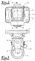
- einen Kupplungsträger in Flanschausführung mit einem Kugelträger und Niederhalter in perspektivischer Darstellung,
- Fig. 2
- den Gegenstand nach Fig. 1 in Frontansicht,
- Fig. 3
- den Gegenstand nach Fig. 2 in Draufsicht,
- Fig. 4
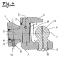
- einen Schnitt AA durch den Gegenstand nach Fig. 2 und
- Fig. 5
- eine abgewandelte Ausführungsform des Gegenstandes nach Fig. 1 mit Kugelkalotte in perspektivischer Darstellung.
- Fig. 1
- a coupling carrier in flange design with a ball carrier and hold-down in perspective view,
- Fig. 2
- the object of FIG. 1 in front view,
- Fig. 3
- the article of FIG. 2 in plan view,
- Fig. 4
- a section AA through the article of FIG. 2 and
- Fig. 5
- a modified embodiment of the article according to Fig. 1 with spherical cap in a perspective view.
In den Figuren ist eine Anhängekupplung für Zugfahrzeuge wie insbesondere Fahrzeuge der Land- und Forstwirtschaft dargestellt. Diese Anhängekupplung weist einen an ein Zugfahrzeug anschließbaren Kupplungsträger 1 und einen in dem Kupplungsträger 1 um eine in Zugrichtung verlaufende Drehachse 2 drehbar gelagerten Kugelträger 3 mit einer Kupplungskugel 4 für eine an einen Anhänger anschließbare Kugelkalotte 5 auf. Ferner ist ein Niederhalter 6 für die die Kupplungskugel 4 im Kupplungszustand übergreifende Kugelkalotte 5 vorgesehen. Dieser Niederhalter 6 ist in dem Kugelträger 3 mittels eines Lagerzapfens, 7 um eine Vertikalachse 8 schwenkbar gelagert und mittels eines den Kugelträger 3 und den Lagerzapfen 7 quer durchdringenden und ziehbaren Verriegelungsbolzens 9 in Niederhalteposition verriegelbar. Die Kupplungskugel 4 ist mittels eines Lagerzapfens 10 in dem Kugelträger 3 austauschbar gelagert und mittels einer Nutmutter 11 auf der Unterseite des Kugelträgers 3 gesichert. Die Drehachse 2 des Kugelträgers verläuft durch den Kugelmittelpunkt M der Kupplungskugel 4, so dass gleichsam ein zentraler Kugelträger 3 verwirklicht wird. Dazu ist der Kugelträger 3 mit einem in Zugrichtung verlaufenden Drehzapfen 12 in dem Kupplungsträger 1 gelagert, wobei die Mittenachse des Drehzapfens 12 die durch den Kugelmittelpunkt M verlaufende Drehachse 2 bildet. Auf der Rückseite des Kupplungsträgers 1 ist zur Sicherung des Kugelträgers 3 ein Lagerring 13 auf den Drehzapfen 12 aufgeschweißt. Dem Drehzapfen 12 ist eine einstellbare Drehsicherung 14 zugeordnet. Bei dieser Drehsicherung 14 handelt es sich in einfacher Ausführungsform um eine Stellschraube 15, die auf ein dem Drehzapfen 12 zugeordnetes Federelement 16 arbeitet.In the figures, a trailer coupling for towing vehicles such as in particular vehicles of agriculture and forestry shown. This trailer coupling has a
Der Kugelträger 3 weist auf seiner der Kupplungskugel 4 zugeordneten Breitseite eine maulartige Zentrierfläche 17 für die Kugelkalotte 5 auf, die mittels eines drehfesten Schaftes 18 an einem Anhänger befestigt werden kann. - Der Kupplungsträger 1 kann als Befestigungsflansch 1a oder höhenverstellbare Flanschplatte 1b ausgebildet sein.The
Claims (6)
- A trailer hitch for tractors with a hitch bracket (1) that can be connected to a tractor and a ball bracket (3) with a hitch ball (4) for a spherical cap (5) that can be connected to a trailer, wherein said ball bracket is supported in the hitch bracket (1) such that it can be turned about an axis of rotation (2) extending in the direction of traction, and with a hold-down device (6) for the spherical cap (5) engaging over the hitch ball (4) in the coupled state, characterized in that the axis of rotation (2) of the ball bracket (3) extends through the center (M) of the hitch ball (4).
- The trailer hitch according to Claim 1, characterized in that the ball bracket (3) is supported in the hitch bracket (1) with a pivot (12) extending in the direction of traction, and in that the center line of the pivot (12) forms the axis of rotation (2) extending through the center (M) of the ball.
- The trailer hitch according to Claim 1 or 2, characterized in that an adjustable rotary lock (14) is assigned to the pivot (12).
- The trailer hitch according to one of Claims 1-3, characterized in that the ball bracket (3) has a mouth-like centering surface (17) for the spherical cap (5) on its broadsides assigned to the hitch ball (4).
- The trailer hitch according to one of Claims 1-4, characterized in that the spherical cap (5) can be mounted on a trailer by means of a non-rotatable shaft (18).
- The trailer hitch according to one of Claims 1-5, characterized in that the hitch bracket (1) is realized in the form of a mounting flange (1a) or a height-adjustable flange plate (1b).
Priority Applications (4)
| Application Number | Priority Date | Filing Date | Title |
|---|---|---|---|
| EP03025220A EP1529667B8 (en) | 2003-11-05 | 2003-11-05 | Ball and socket hitch |
| AT03025220T ATE321676T1 (en) | 2003-11-05 | 2003-11-05 | BALL COUPLING |
| DE50302794T DE50302794D1 (en) | 2003-11-05 | 2003-11-05 | ball coupling |
| DE20318531U DE20318531U1 (en) | 2003-11-05 | 2003-11-29 | Towing |
Applications Claiming Priority (1)
| Application Number | Priority Date | Filing Date | Title |
|---|---|---|---|
| EP03025220A EP1529667B8 (en) | 2003-11-05 | 2003-11-05 | Ball and socket hitch |
Publications (3)
| Publication Number | Publication Date |
|---|---|
| EP1529667A1 EP1529667A1 (en) | 2005-05-11 |
| EP1529667B1 true EP1529667B1 (en) | 2006-03-29 |
| EP1529667B8 EP1529667B8 (en) | 2006-06-21 |
Family
ID=31985192
Family Applications (1)
| Application Number | Title | Priority Date | Filing Date |
|---|---|---|---|
| EP03025220A Expired - Lifetime EP1529667B8 (en) | 2003-11-05 | 2003-11-05 | Ball and socket hitch |
Country Status (3)
| Country | Link |
|---|---|
| EP (1) | EP1529667B8 (en) |
| AT (1) | ATE321676T1 (en) |
| DE (2) | DE50302794D1 (en) |
Families Citing this family (4)
| Publication number | Priority date | Publication date | Assignee | Title |
|---|---|---|---|---|
| ITMO20040145A1 (en) | 2004-06-08 | 2004-09-08 | Cbm Spa | TOWING DEVICE FOR TRAILERS, TOOLS AND MACHINES IN GENERAL. |
| EP1820672B1 (en) * | 2006-02-17 | 2009-04-15 | GKN Walterscheid Cramer GmbH | Trailer hitch for towing vehicles |
| DE102018132070B4 (en) | 2018-12-13 | 2021-10-14 | Pfanzelt Maschinenbau Gmbh | trailer hitch |
| CN111591092B (en) * | 2020-06-02 | 2021-07-20 | 唐山观畴科技有限公司 | Trailer connecting device convenient to split |
Family Cites Families (5)
| Publication number | Priority date | Publication date | Assignee | Title |
|---|---|---|---|---|
| WO1989004260A1 (en) * | 1987-11-13 | 1989-05-18 | Lynline Pty Limited | Coupling arrangement |
| US5853187A (en) * | 1996-11-22 | 1998-12-29 | Maier; James P. | Snowmobile hitch |
| WO2001032451A1 (en) * | 1999-10-29 | 2001-05-10 | Wing Enterprises, Inc. | Pivoting, underslung, stowaway, hitch mount |
| EP1145876A1 (en) * | 2000-04-10 | 2001-10-17 | PEKA Fahrzeugbau GmbH & Co | Moter vehicle trailer coupling |
| US6974148B2 (en) * | 2000-04-27 | 2005-12-13 | B & W Custom Truck Beds, Inc. | Low-profile, hitch-concealing mount |
-
2003
- 2003-11-05 DE DE50302794T patent/DE50302794D1/en not_active Expired - Lifetime
- 2003-11-05 AT AT03025220T patent/ATE321676T1/en active
- 2003-11-05 EP EP03025220A patent/EP1529667B8/en not_active Expired - Lifetime
- 2003-11-29 DE DE20318531U patent/DE20318531U1/en not_active Expired - Lifetime
Also Published As
| Publication number | Publication date |
|---|---|
| DE20318531U1 (en) | 2004-03-04 |
| EP1529667B8 (en) | 2006-06-21 |
| EP1529667A1 (en) | 2005-05-11 |
| DE50302794D1 (en) | 2006-05-18 |
| ATE321676T1 (en) | 2006-04-15 |
Similar Documents
| Publication | Publication Date | Title |
|---|---|---|
| EP1435305B1 (en) | Trailer coupling | |
| EP1380445B2 (en) | Trailer traction device | |
| EP1529667B1 (en) | Ball and socket hitch | |
| EP2660082B1 (en) | Trailer coupling with a screw-on fixing element | |
| DE102004044912A1 (en) | Trailer coupling for motor vehicle, has storage component fixed to carrier part of motor vehicle and ball joint transferring forces arising between vehicle and trailer in operating position | |
| DE3918387A1 (en) | FENDER ADJUSTABLE IN DIFFERENT DIRECTIONS | |
| DE202004006666U1 (en) | Motor vehicle trailer coupling has hitch arm with motorized retractable mounting and rotary bearing to support arm with respect to chassis | |
| DE102006051096A1 (en) | Tow coupling for motor vehicle and bicycle, has coupling arm pivotable from use position to idle position and vice-versa, where arm is pivotable around central point and around not fixed axis, which runs through central point | |
| DE10347816B4 (en) | Trailer coupling with load-free pivot bearing device | |
| EP1398185B1 (en) | Trailer coupling | |
| DE3702699C2 (en) | Device for stabilizing a trailer | |
| DE19609910C2 (en) | Bicycle trailer coupling | |
| EP2265451B1 (en) | Pivotable trailer coupling | |
| EP3666558B1 (en) | Trailer coupling | |
| EP2705739B1 (en) | Reversible plough | |
| DE102013012525A1 (en) | Trailer coupling system for motor vehicles | |
| DE2643308C2 (en) | Trailer coupling for connecting a trailer to a towing vehicle | |
| DE102014210165B4 (en) | LOCKING UNIT FOR A VEHICLE SEAT AND VEHICLE SEAT | |
| EP2671739A2 (en) | Actuation system for a trailer coupling of a motor vehicle | |
| DE102021208912B3 (en) | lifting glasses for vehicles | |
| EP1634774B1 (en) | Load carrier for retractable hitch | |
| DE102016225560A1 (en) | Single-track vehicle with locking module | |
| DE102004012483B4 (en) | Coupling device for connecting a towing vehicle with a trailer | |
| DE202004006228U1 (en) | Trailer coupling for a vehicle | |
| DE10251395B3 (en) | Trailer coupling for pulling trailer with traction vehicle has spherical-surfaced component able to turn about axis |
Legal Events
| Date | Code | Title | Description |
|---|---|---|---|
| PUAI | Public reference made under article 153(3) epc to a published international application that has entered the european phase |
Free format text: ORIGINAL CODE: 0009012 |
|
| AK | Designated contracting states |
Kind code of ref document: A1 Designated state(s): AT BE BG CH CY CZ DE DK EE ES FI FR GB GR HU IE IT LI LU MC NL PT RO SE SI SK TR |
|
| AX | Request for extension of the european patent |
Extension state: AL LT LV MK |
|
| GRAP | Despatch of communication of intention to grant a patent |
Free format text: ORIGINAL CODE: EPIDOSNIGR1 |
|
| 17P | Request for examination filed |
Effective date: 20050729 |
|
| GRAS | Grant fee paid |
Free format text: ORIGINAL CODE: EPIDOSNIGR3 |
|
| AKX | Designation fees paid |
Designated state(s): AT BE BG CH CY CZ DE DK EE ES FI FR GB GR HU IE IT LI LU MC NL PT RO SE SI SK TR |
|
| GRAA | (expected) grant |
Free format text: ORIGINAL CODE: 0009210 |
|
| AK | Designated contracting states |
Kind code of ref document: B1 Designated state(s): AT BE BG CH CY CZ DE DK EE ES FI FR GB GR HU IE IT LI LU MC NL PT RO SE SI SK TR |
|
| PG25 | Lapsed in a contracting state [announced via postgrant information from national office to epo] |
Ref country code: SK Free format text: LAPSE BECAUSE OF FAILURE TO SUBMIT A TRANSLATION OF THE DESCRIPTION OR TO PAY THE FEE WITHIN THE PRESCRIBED TIME-LIMIT Effective date: 20060329 Ref country code: IT Free format text: LAPSE BECAUSE OF FAILURE TO SUBMIT A TRANSLATION OF THE DESCRIPTION OR TO PAY THE FEE WITHIN THE PRESCRIBED TIME-LIMIT;WARNING: LAPSES OF ITALIAN PATENTS WITH EFFECTIVE DATE BEFORE 2007 MAY HAVE OCCURRED AT ANY TIME BEFORE 2007. THE CORRECT EFFECTIVE DATE MAY BE DIFFERENT FROM THE ONE RECORDED. Effective date: 20060329 Ref country code: SI Free format text: LAPSE BECAUSE OF FAILURE TO SUBMIT A TRANSLATION OF THE DESCRIPTION OR TO PAY THE FEE WITHIN THE PRESCRIBED TIME-LIMIT Effective date: 20060329 Ref country code: IE Free format text: LAPSE BECAUSE OF FAILURE TO SUBMIT A TRANSLATION OF THE DESCRIPTION OR TO PAY THE FEE WITHIN THE PRESCRIBED TIME-LIMIT Effective date: 20060329 Ref country code: RO Free format text: LAPSE BECAUSE OF FAILURE TO SUBMIT A TRANSLATION OF THE DESCRIPTION OR TO PAY THE FEE WITHIN THE PRESCRIBED TIME-LIMIT Effective date: 20060329 |
|
| REG | Reference to a national code |
Ref country code: GB Ref legal event code: FG4D Free format text: NOT ENGLISH |
|
| REG | Reference to a national code |
Ref country code: CH Ref legal event code: EP |
|
| REG | Reference to a national code |
Ref country code: IE Ref legal event code: FG4D Free format text: LANGUAGE OF EP DOCUMENT: GERMAN |
|
| REF | Corresponds to: |
Ref document number: 50302794 Country of ref document: DE Date of ref document: 20060518 Kind code of ref document: P |
|
| RAP2 | Party data changed (patent owner data changed or rights of a patent transferred) |
Owner name: GKN WALTERSCHEID CRAMER GMBH |
|
| PG25 | Lapsed in a contracting state [announced via postgrant information from national office to epo] |
Ref country code: BG Free format text: LAPSE BECAUSE OF FAILURE TO SUBMIT A TRANSLATION OF THE DESCRIPTION OR TO PAY THE FEE WITHIN THE PRESCRIBED TIME-LIMIT Effective date: 20060629 Ref country code: DK Free format text: LAPSE BECAUSE OF FAILURE TO SUBMIT A TRANSLATION OF THE DESCRIPTION OR TO PAY THE FEE WITHIN THE PRESCRIBED TIME-LIMIT Effective date: 20060629 Ref country code: SE Free format text: LAPSE BECAUSE OF FAILURE TO SUBMIT A TRANSLATION OF THE DESCRIPTION OR TO PAY THE FEE WITHIN THE PRESCRIBED TIME-LIMIT Effective date: 20060629 |
|
| REG | Reference to a national code |
Ref country code: GB Ref legal event code: 732E |
|
| PG25 | Lapsed in a contracting state [announced via postgrant information from national office to epo] |
Ref country code: ES Free format text: LAPSE BECAUSE OF FAILURE TO SUBMIT A TRANSLATION OF THE DESCRIPTION OR TO PAY THE FEE WITHIN THE PRESCRIBED TIME-LIMIT Effective date: 20060710 |
|
| NLT2 | Nl: modifications (of names), taken from the european patent patent bulletin |
Owner name: GKN WALTERSCHEID CRAMER GMBH Effective date: 20060607 |
|
| GBT | Gb: translation of ep patent filed (gb section 77(6)(a)/1977) |
Effective date: 20060712 |
|
| PG25 | Lapsed in a contracting state [announced via postgrant information from national office to epo] |
Ref country code: PT Free format text: LAPSE BECAUSE OF FAILURE TO SUBMIT A TRANSLATION OF THE DESCRIPTION OR TO PAY THE FEE WITHIN THE PRESCRIBED TIME-LIMIT Effective date: 20060829 |
|
| REG | Reference to a national code |
Ref country code: HU Ref legal event code: AG4A Ref document number: E000639 Country of ref document: HU |
|
| REG | Reference to a national code |
Ref country code: IE Ref legal event code: FD4D |
|
| PGFP | Annual fee paid to national office [announced via postgrant information from national office to epo] |
Ref country code: HU Payment date: 20061117 Year of fee payment: 4 |
|
| ET | Fr: translation filed | ||
| PG25 | Lapsed in a contracting state [announced via postgrant information from national office to epo] |
Ref country code: BE Free format text: LAPSE BECAUSE OF NON-PAYMENT OF DUE FEES Effective date: 20061130 Ref country code: MC Free format text: LAPSE BECAUSE OF NON-PAYMENT OF DUE FEES Effective date: 20061130 |
|
| NLS | Nl: assignments of ep-patents |
Owner name: GKN WALTERSCHEID CRAMER GMBH Effective date: 20061120 |
|
| PLBE | No opposition filed within time limit |
Free format text: ORIGINAL CODE: 0009261 |
|
| STAA | Information on the status of an ep patent application or granted ep patent |
Free format text: STATUS: NO OPPOSITION FILED WITHIN TIME LIMIT |
|
| 26N | No opposition filed |
Effective date: 20070102 |
|
| BERE | Be: lapsed |
Owner name: CRAMER KUPPLUNG G.M.B.H. & CO. KG Effective date: 20061130 |
|
| PG25 | Lapsed in a contracting state [announced via postgrant information from national office to epo] |
Ref country code: CZ Free format text: LAPSE BECAUSE OF FAILURE TO SUBMIT A TRANSLATION OF THE DESCRIPTION OR TO PAY THE FEE WITHIN THE PRESCRIBED TIME-LIMIT Effective date: 20060329 Ref country code: GR Free format text: LAPSE BECAUSE OF FAILURE TO SUBMIT A TRANSLATION OF THE DESCRIPTION OR TO PAY THE FEE WITHIN THE PRESCRIBED TIME-LIMIT Effective date: 20060630 |
|
| PG25 | Lapsed in a contracting state [announced via postgrant information from national office to epo] |
Ref country code: EE Free format text: LAPSE BECAUSE OF FAILURE TO SUBMIT A TRANSLATION OF THE DESCRIPTION OR TO PAY THE FEE WITHIN THE PRESCRIBED TIME-LIMIT Effective date: 20060329 Ref country code: FI Free format text: LAPSE BECAUSE OF FAILURE TO SUBMIT A TRANSLATION OF THE DESCRIPTION OR TO PAY THE FEE WITHIN THE PRESCRIBED TIME-LIMIT Effective date: 20060329 |
|
| PG25 | Lapsed in a contracting state [announced via postgrant information from national office to epo] |
Ref country code: HU Free format text: LAPSE BECAUSE OF NON-PAYMENT OF DUE FEES Effective date: 20071106 Ref country code: LI Free format text: LAPSE BECAUSE OF NON-PAYMENT OF DUE FEES Effective date: 20071130 Ref country code: TR Free format text: LAPSE BECAUSE OF FAILURE TO SUBMIT A TRANSLATION OF THE DESCRIPTION OR TO PAY THE FEE WITHIN THE PRESCRIBED TIME-LIMIT Effective date: 20060329 Ref country code: LU Free format text: LAPSE BECAUSE OF NON-PAYMENT OF DUE FEES Effective date: 20061105 Ref country code: CH Free format text: LAPSE BECAUSE OF NON-PAYMENT OF DUE FEES Effective date: 20071130 |
|
| REG | Reference to a national code |
Ref country code: CH Ref legal event code: PL |
|
| PG25 | Lapsed in a contracting state [announced via postgrant information from national office to epo] |
Ref country code: CY Free format text: LAPSE BECAUSE OF FAILURE TO SUBMIT A TRANSLATION OF THE DESCRIPTION OR TO PAY THE FEE WITHIN THE PRESCRIBED TIME-LIMIT Effective date: 20060329 |
|
| PGFP | Annual fee paid to national office [announced via postgrant information from national office to epo] |
Ref country code: NL Payment date: 20081120 Year of fee payment: 6 |
|
| PGFP | Annual fee paid to national office [announced via postgrant information from national office to epo] |
Ref country code: IT Payment date: 20081125 Year of fee payment: 6 |
|
| PGFP | Annual fee paid to national office [announced via postgrant information from national office to epo] |
Ref country code: GB Payment date: 20081121 Year of fee payment: 6 |
|
| REG | Reference to a national code |
Ref country code: NL Ref legal event code: V1 Effective date: 20100601 |
|
| GBPC | Gb: european patent ceased through non-payment of renewal fee |
Effective date: 20091105 |
|
| PG25 | Lapsed in a contracting state [announced via postgrant information from national office to epo] |
Ref country code: NL Free format text: LAPSE BECAUSE OF NON-PAYMENT OF DUE FEES Effective date: 20100601 |
|
| PG25 | Lapsed in a contracting state [announced via postgrant information from national office to epo] |
Ref country code: GB Free format text: LAPSE BECAUSE OF NON-PAYMENT OF DUE FEES Effective date: 20091105 |
|
| PG25 | Lapsed in a contracting state [announced via postgrant information from national office to epo] |
Ref country code: IT Free format text: LAPSE BECAUSE OF NON-PAYMENT OF DUE FEES Effective date: 20091105 |
|
| REG | Reference to a national code |
Ref country code: FR Ref legal event code: PLFP Year of fee payment: 13 |
|
| REG | Reference to a national code |
Ref country code: FR Ref legal event code: PLFP Year of fee payment: 14 |
|
| REG | Reference to a national code |
Ref country code: FR Ref legal event code: PLFP Year of fee payment: 15 |
|
| REG | Reference to a national code |
Ref country code: DE Ref legal event code: R082 Ref document number: 50302794 Country of ref document: DE Representative=s name: NEUMANN MUELLER OBERWALLENEY & PARTNER PATENTA, DE Ref country code: DE Ref legal event code: R081 Ref document number: 50302794 Country of ref document: DE Owner name: WALTERSCHEID GMBH, DE Free format text: FORMER OWNER: GKN WALTERSCHEID CRAMER GMBH, 53797 LOHMAR, DE |
|
| PGFP | Annual fee paid to national office [announced via postgrant information from national office to epo] |
Ref country code: FR Payment date: 20221118 Year of fee payment: 20 Ref country code: DE Payment date: 20221121 Year of fee payment: 20 Ref country code: AT Payment date: 20221117 Year of fee payment: 20 |
|
| REG | Reference to a national code |
Ref country code: DE Ref legal event code: R071 Ref document number: 50302794 Country of ref document: DE |
|
| REG | Reference to a national code |
Ref country code: AT Ref legal event code: MK07 Ref document number: 321676 Country of ref document: AT Kind code of ref document: T Effective date: 20231105 |