EP1529478A2 - Power scrubber - Google Patents
Power scrubber Download PDFInfo
- Publication number
- EP1529478A2 EP1529478A2 EP04012739A EP04012739A EP1529478A2 EP 1529478 A2 EP1529478 A2 EP 1529478A2 EP 04012739 A EP04012739 A EP 04012739A EP 04012739 A EP04012739 A EP 04012739A EP 1529478 A2 EP1529478 A2 EP 1529478A2
- Authority
- EP
- European Patent Office
- Prior art keywords
- scrubbing
- head
- fluid
- scrubbing device
- support
- Prior art date
- Legal status (The legal status is an assumption and is not a legal conclusion. Google has not performed a legal analysis and makes no representation as to the accuracy of the status listed.)
- Granted
Links
Images


Classifications
-
- A—HUMAN NECESSITIES
- A47—FURNITURE; DOMESTIC ARTICLES OR APPLIANCES; COFFEE MILLS; SPICE MILLS; SUCTION CLEANERS IN GENERAL
- A47L—DOMESTIC WASHING OR CLEANING; SUCTION CLEANERS IN GENERAL
- A47L11/00—Machines for cleaning floors, carpets, furniture, walls, or wall coverings
- A47L11/40—Parts or details of machines not provided for in groups A47L11/02 - A47L11/38, or not restricted to one of these groups, e.g. handles, arrangements of switches, skirts, buffers, levers
-
- A—HUMAN NECESSITIES
- A47—FURNITURE; DOMESTIC ARTICLES OR APPLIANCES; COFFEE MILLS; SPICE MILLS; SUCTION CLEANERS IN GENERAL
- A47L—DOMESTIC WASHING OR CLEANING; SUCTION CLEANERS IN GENERAL
- A47L11/00—Machines for cleaning floors, carpets, furniture, walls, or wall coverings
- A47L11/02—Floor surfacing or polishing machines
- A47L11/03—Floor surfacing or polishing machines characterised by having provisions for supplying cleaning or polishing agents
-
- A—HUMAN NECESSITIES
- A47—FURNITURE; DOMESTIC ARTICLES OR APPLIANCES; COFFEE MILLS; SPICE MILLS; SUCTION CLEANERS IN GENERAL
- A47L—DOMESTIC WASHING OR CLEANING; SUCTION CLEANERS IN GENERAL
- A47L11/00—Machines for cleaning floors, carpets, furniture, walls, or wall coverings
- A47L11/28—Floor-scrubbing machines, motor-driven
- A47L11/282—Floor-scrubbing machines, motor-driven having rotary tools
-
- A—HUMAN NECESSITIES
- A47—FURNITURE; DOMESTIC ARTICLES OR APPLIANCES; COFFEE MILLS; SPICE MILLS; SUCTION CLEANERS IN GENERAL
- A47L—DOMESTIC WASHING OR CLEANING; SUCTION CLEANERS IN GENERAL
- A47L11/00—Machines for cleaning floors, carpets, furniture, walls, or wall coverings
- A47L11/40—Parts or details of machines not provided for in groups A47L11/02 - A47L11/38, or not restricted to one of these groups, e.g. handles, arrangements of switches, skirts, buffers, levers
- A47L11/4036—Parts or details of the surface treating tools
- A47L11/4038—Disk shaped surface treating tools
-
- A—HUMAN NECESSITIES
- A47—FURNITURE; DOMESTIC ARTICLES OR APPLIANCES; COFFEE MILLS; SPICE MILLS; SUCTION CLEANERS IN GENERAL
- A47L—DOMESTIC WASHING OR CLEANING; SUCTION CLEANERS IN GENERAL
- A47L11/00—Machines for cleaning floors, carpets, furniture, walls, or wall coverings
- A47L11/40—Parts or details of machines not provided for in groups A47L11/02 - A47L11/38, or not restricted to one of these groups, e.g. handles, arrangements of switches, skirts, buffers, levers
- A47L11/4075—Handles; levers
-
- A—HUMAN NECESSITIES
- A47—FURNITURE; DOMESTIC ARTICLES OR APPLIANCES; COFFEE MILLS; SPICE MILLS; SUCTION CLEANERS IN GENERAL
- A47L—DOMESTIC WASHING OR CLEANING; SUCTION CLEANERS IN GENERAL
- A47L11/00—Machines for cleaning floors, carpets, furniture, walls, or wall coverings
- A47L11/40—Parts or details of machines not provided for in groups A47L11/02 - A47L11/38, or not restricted to one of these groups, e.g. handles, arrangements of switches, skirts, buffers, levers
- A47L11/408—Means for supplying cleaning or surface treating agents
- A47L11/4088—Supply pumps; Spraying devices; Supply conduits
Definitions
- the present invention relates to cleaning devices and, more particularly, to a battery operated scrubbing device.
- a scrubbing device which includes a power source for rotating the cleaning member such as a brush, sponge or the like.
- a cleaning device is illustrated in U.S. Patent No. 5,289,605.
- the scrubbing device includes a battery pack, which is mounted onto the user.
- U.S. Patent D451,288 illustrates a scrubbing device. This device includes a telescoping handle. While these devices enable the user to clean various surfaces, designers strive to improve the art.
- the present invention provides a scrubbing device that is battery operated and has a separate source of water as well as cleaning solution.
- the present invention provides a scrubber, which includes a cleaning solution reservoir, which may be permanently or removably attached to the scrubber.
- the scrubber includes a pivoted head which may be locked in position or which may be in a tree motion position. The head of the scrubber is submersible into a liquid.
- a scrubbing device comprises a scrubbing head with a cleaning member and an electric motor driving the cleaning member.
- a support member is coupled with the scrubbing head.
- a handle is coupled with the support member and includes a switch to activate the electric motor.
- a first fluid source is coupled with the scrubbing head for spraying the first fluid on a surface to be cleaned.
- a second fluid source is coupled with the scrubbing head to spray a second fluid on the surface to be cleaned.
- the scrubbing head is submersible into a liquid.
- the fluid reservoir is coupled with the support member.
- a fluid line couples the fluid reservoir with the second fluid source coupled with the scrubbing head.
- a hose is coupled with the first fluid source.
- the first fluid source includes a fluid conduit extending from the handle to the scrubbing head.
- the handle includes a hose receiving member and a hose retention member.
- the handle includes an aperture for receiving the battery.
- the first and second fluid sources each include a nozzle on the scrubbing head to enable spraying of the fluids onto the surface.
- a pivot locking mechanism couples the support with the scrubbing head. The pivot locking mechanism enables locking of the scrubbing head with respect to the support in a first position. Also, the pivot lock enables free motion of the scrubbing head with respect to the support in the second position.
- the support is telescopic.
- the cleaning mechanism includes a retention member with a circumferential wall defining a bore.
- a flange projects from the inner surface of the wall into the bore to couple the cleaning member with a motor shaft.
- the wall is divided into sections forming at least one finger with the flange to retain the cleaning member.
- the scrubbing head includes a housing to receive a portion of the first and second fluid sources.
- a pump is provided in the handle to deliver a fluid to the second fluid source.
- the pump and switch is coupled with the reservoir to spray the second fluid onto the cleaning surface.
- the scrubbing device includes a head 12, a support member 14 and a handle 16.
- the handle 16 includes a coupling member 18 to connect the scrubbing device 10 with a hose 20.
- the handle 16 includes a clamshell housing 22 with a grip portion 24, as well as an aperture 26 to enable the users hand to pass through the aperture and secure on the grip portion 24.
- a battery 28 is inserted through an aperture 30 at one end of the housing 22.
- the handle 16 includes a hose retention member 32.
- the hose retention member includes a latch 34 and an arcuate groove 36 which receives the hose 20.
- the latch 34 extends over the hose 20 locking the hose in the groove 36 so that the hose does not place a large bending moment on the hose connecting element 18.
- the hose connecting element 18 is connected to a conduit 40.
- the conduit 40 passes water from the hose to the scrubbing head 12.
- a switch 42 on the handle 16 controls the power to the motor.
- the motor may be turned on and off by switch 42.
- a valve 41 integrated with element 18, associated with the conduit 40 enables variable volumes of the water to pass to the scrubbing head so that the amount of water can be controlled to the surface to be cleaned.
- An air pump 44 is positioned within the handle 16. See Figure 9.
- the air pump 44 can be controlled by switch 46.
- the air pump is electrically coupled with the battery pack 28.
- the air pump 44 controls the amount of fluid sprayed out of the second fluid source.
- the support 14 includes a number of sections 50 to enable telescoping of the support 14. Further, a gripping member 52 may be positioned on the outside of the support member.
- the conduit 40 is positioned between the gripping member 52 and the support 14 until it reaches a spacer 54.
- the conduit 40 includes a spiral conduit portion 56 which elongates to enable telescoping of the support 14.
- the spiral conduit portion 56 connects with a lower conduit portion of the first fluid source.
- a spiraled wire 60, as well as air hose 62, are inside of the sections 50 of the support 14.
- the wire 60 is electrically connected with switch 42 and, in turn, battery 28 to drive the electric motor 64 and in turn the scrubbing device on the scrubber head 12.
- the air hose 62 extends from one of the support sections 50 and passes into the reservoir 66 of the lower portion 58.
- the lower portion 58 includes the cleaning solution reservoir 66, as well as a fork portion 68 which couples with the head 12.
- the cleaning solution reservoir 66 may be removable from the lower portion 58.
- the air hose 62 couples with an inlet to the cleaning solution reservoir 66.
- the cleaning solution reservoir 66 includes an outlet 70 which includes another conduit 72 which passes into the scrubber head 12 and connects with the nozzle 74. Thus, fluid cleaning solution is moved from the reservoir 66, via the pump 44, and sprays out the nozzle 74.
- the fork 68 of the lower portion pivotally secures with the head 12.
- the fork portion 68 includes a pivot locking mechanism 80 which enables the head 12 to be locked in at least one position and also enables free motion of the head about the fork 68.
- the head housing 100 includes a boss 120 having a cam retention area 122 and a pivot pin 124.
- the cam retention area 122 includes a plurality of recesses 126 and projections 128 which receive a head locking gear 130.
- the head locking gear 130 is a metal gear including a plurality of projections 132 and recesses 134.
- the projections 132 and recesses 134 mate with the boss recesses and projections 126 and 128 so that the head locking gear 130 is secured in position in the boss 120.
- One of the recesses 134 includes a wedge 136, which projects through a slot 138 in the boss 120.
- the wedge 136 acts as a stop to halt the rotation of the fork 68 on the head 12, which will be explained herein.
- the pivot locking mechanism 80 includes a rotatable knob 142 and a sliding cam plate 144.
- the rotatable knob 142 includes an offset receiving portion 143 to retain the knob 142 onto the pivot 124.
- the knob 142 includes an eccentric cam surface 146.
- the cam surface 146 abuts against a tab 148 of the sliding cam plate 144.
- the cam plate 144 includes a tab 145 which retains a plurality of pins 150 which mate in the recesses 134 of the head locking gear 130.
- the pins 150 are loaded by springs 152, which are retained in a housing portion 154 of the fork 68.
- a plate 155 secures the sliding cam plate 144 in the housing portion 154.
- the housing portion 154 includes an arcuate portion 156 and a rectangular portion 158.
- the arcuate portion 156 fits around the cylindrical boss 120 enabling the fork 68 to rotate about the boss 120.
- the arcuate portion 156 has ends 160 and 161 which act as stops and abut the wedge 136 stopping rotation of the fork 68.
- the wedge 136 acts as a stop to limit the rotation in both directions of the fork 68 (see Figure 7).
- the sliding cam plate 144, with pins 150 biased by springs 152, are positioned in the rectangular portion 158 of the housing 154. As the knob 142 is rotated, with eccentric cam surface 146 abutting against tab 148, the sliding cam plate 144, as well as pins 150, is moved in the housing portion 158.
- This movement removes the pins 150 from the recesses 134 of the head locking gear 130.
- the knob 142 is rotated in a reverse direction to enable the pins 150 to engage different recesses 134 in the head locking gear 130 to lock the fork 68 in a different position with respect to the head 12.
- the knob 142 is rotated, which, in turn, moves the sliding cam plate 144, as well as pins 150, away from the head locking gear 130 out of engagement with recesses 134.
- the pins 150 do not extend into the recesses 134.
- the fork 68 can rotate until the stops 160 and 161 contact wedge 136 halting the rotation of the fork 68.
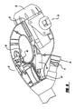
- the head 12 is submersible into a liquid such as water and has a water tight seal. Thus, the head 12 may be placed into a bucket of water or the like when in use.
- the head 12 includes housing 100 surrounding the motor 64 positioned within the housing 100.
- a cleaning device such as a brush 102, is secured to a motor shaft 104 of the motor 64.
- the housing 100 includes passageways 106 to enable the soap and water conduits to pass to the nozzles 74 and 108.
- the nozzle 108 is coupled with the water conduit 40.
- the cleaning member 102 includes a retention member 110 which has a circumferential wall 112.
- the wall 112 defines a bore 114.
- a circumferential flange 116 is positioned on the interior surface of the bore 114.
- the circumferential wall includes slots forming sections which, in turn, form fingers 118 to retain the cleaning member 102 onto the motor shaft 104.
- the wall 112 is placed on the shaft and is expanded due to the flange. Once the flange intercepts the groove, the wall is secured on the shaft.
- the scrubbing device 10 includes a first fluid source which includes the hose connection 18, conduit 40 and nozzle 108.
- the valve 41 connected with the conduit 40 is open to enable fluid from the hose to pass into the conduit 40. This fluid passes through the conduit 40 through the spiral section and out of nozzle 108.
- the switch 46 activates the pump 44. This forces air into the hose 62 which, in turn, pressurizes the reservoir 66. As the reservoir 66 pressurizes, cleaning solution in the reservoir is passed through hose 72 and out of nozzle 74.
- the switch 42 can activate the cleaning device at any time during these operations. Thus, cleaning solution and water are separately ejected from the scrubber and are not mixed with one another prior to ejection onto the surface to be cleaned.
- a cleaning device which may be extended to reach vertical heights above the user. Also, the device may be positioned in a free motion pivoting position so that the head may continue to follow the surface as it is scrubbed. Further, the invention provides a lightweight battery operated scrubbing device, which is easily manipulated by the user.
Landscapes
- Cleaning By Liquid Or Steam (AREA)
- Brushes (AREA)
- Gas Separation By Absorption (AREA)
- Glass Compositions (AREA)
- Reciprocating, Oscillating Or Vibrating Motors (AREA)
Abstract
Description
Claims (17)
- A scrubbing device comprising:a scrubbing head including a cleaning member and an electrical motor driving said cleaning member;a support member coupled with said scrubbing head;a handle coupled with said support member;a switch for activating said electric motor,a first fluid source coupled with said scrubbing head for spraying a first fluid on a surface to be cleaned;a second fluid source coupled with said scrubbing head for spraying a second fluid on the surface to be cleaned.
- The scrubbing device according to Claim 1 wherein said scrubbing head is submersible into a liquid.
- The scrubbing device according to Claim 1 wherein said handle includes an aperture for receiving a battery.
- The scrubbing device according to Claim 1 wherein a fluid reservoir is coupled with said support member.
- The scrubbing device according to Claim 4 wherein a fluid line couples said fluid reservoir in said second fluid source coupled with said scrubbing head.
- The scrubbing device according to Claim 1 wherein a hose is coupled with said first fluid source.
- The scrubbing device according to Claim 6 wherein said first fluid source includes a fluid line extending from said handle to said scrubbing head.
- The scrubbing device according to Claim 1 wherein said first and second fluid sources each include a nozzle on said scrubbing head.
- The scrubbing device according to Claim 6 wherein said handle includes a hose receiving member and a hose retention member.
- The scrubbing device according to Claim 1 wherein a pivot locking mechanism couples said support with said scrubbing head, said pivot locking mechanism enabling locking of the scrubbing head with respect to the support in a first position and enabling free motion of the scrubbing head with respect to the support in a second position.
- The scrubbing device according to Claim 1 wherein said support is a telescoping support.
- The scrubbing device according to Claim 1 wherein said cleaning mechanism includes a retention member having a bore and a flange projecting from a wall of said bore for coupling with a groove in a motor shaft.
- The scrubbing device according to Claim 12 wherein said wall is divided into sections forming at least one finger having said flange for retaining said cleaning member.
- The scrubbing device according to Claim 1 wherein said scrubbing head including a housing for receiving a portion of said first and second fluid sources.
- The scrubbing device according to Claim 1 wherein a pump and switch are provided in said handle for delivering a fluid through said second fluid source.
- The scrubbing device according to Claim 15 wherein said pump is coupled with said reservoir for spraying said second fluid onto the surface.
- The scrubbing device according to Claim 10 wherein said pivot locking mechanism includes a stop for contacting said support for limiting rotational movement of said support with respect to said scrubbing head.
Applications Claiming Priority (2)
| Application Number | Priority Date | Filing Date | Title |
|---|---|---|---|
| US703376 | 2003-11-07 | ||
| US10/703,376 US20040237228A1 (en) | 2003-05-29 | 2003-11-07 | Power scrubber |
Publications (3)
| Publication Number | Publication Date |
|---|---|
| EP1529478A2 true EP1529478A2 (en) | 2005-05-11 |
| EP1529478A3 EP1529478A3 (en) | 2006-02-08 |
| EP1529478B1 EP1529478B1 (en) | 2007-04-25 |
Family
ID=34435572
Family Applications (1)
| Application Number | Title | Priority Date | Filing Date |
|---|---|---|---|
| EP04012739A Expired - Lifetime EP1529478B1 (en) | 2003-11-07 | 2004-05-28 | Power scrubber |
Country Status (4)
| Country | Link |
|---|---|
| EP (1) | EP1529478B1 (en) |
| AT (1) | ATE360390T1 (en) |
| DE (1) | DE602004006066T2 (en) |
| ES (1) | ES2283902T3 (en) |
Cited By (7)
| Publication number | Priority date | Publication date | Assignee | Title |
|---|---|---|---|---|
| EP1913858A2 (en) | 2006-10-19 | 2008-04-23 | Black & Decker, Inc. | Pole Scrubber |
| CN105640447A (en) * | 2016-04-06 | 2016-06-08 | 于宝林 | Electric mop capable of automatically moving forward and automatically cleaning mop cloth |
| CN110340042A (en) * | 2018-04-02 | 2019-10-18 | 苏州宝时得电动工具有限公司 | Water-driven brush and the cleaning machine for using the water-driven brush |
| CN112536262A (en) * | 2019-09-20 | 2021-03-23 | 苏州宝时得电动工具有限公司 | DC cleaning machine |
| WO2022083447A1 (en) * | 2020-10-22 | 2022-04-28 | 北京石头世纪科技股份有限公司 | Mopping module and cleaning head |
| EP4101361A3 (en) * | 2021-05-19 | 2023-02-22 | Techtronic Cordless GP | Fluid dispensing scrubber |
| US12178311B2 (en) | 2020-11-03 | 2024-12-31 | Techtronic Cordless Gp | Drive coupler for power scrubber |
Families Citing this family (2)
| Publication number | Priority date | Publication date | Assignee | Title |
|---|---|---|---|---|
| EP2783615B1 (en) | 2013-03-27 | 2016-05-04 | Walter Jobb | Device for cleaning smooth surfaces |
| DE102013005234B3 (en) * | 2013-03-27 | 2014-08-28 | Walter Jobb | Apparatus for cleaning smooth surfaces, particularly windscreens of truck, has wiper element and pump, which are designed as electric motor that is supplied with electricity by power source and spray nozzle to act cleaning liquid by pump |
Family Cites Families (5)
| Publication number | Priority date | Publication date | Assignee | Title |
|---|---|---|---|---|
| US5289605A (en) * | 1991-12-10 | 1994-03-01 | Armbruster Joseph M | DC powered scrubber |
| FR2715875B1 (en) * | 1994-02-08 | 1996-04-12 | Dms | Cleaning device, method implemented by the device and device applications. |
| US6374447B1 (en) * | 1999-04-16 | 2002-04-23 | Joseph M. Armbruster | Cordless rechargeable powered washing system |
| USD451288S1 (en) * | 2000-09-26 | 2001-12-04 | International Concepts, Inc. | Hand-held washer |
| US6748619B2 (en) * | 2002-03-22 | 2004-06-15 | Trung Thieu Quach | Hand held, electric cleaning device |
-
2004
- 2004-05-28 DE DE602004006066T patent/DE602004006066T2/en not_active Expired - Lifetime
- 2004-05-28 EP EP04012739A patent/EP1529478B1/en not_active Expired - Lifetime
- 2004-05-28 AT AT04012739T patent/ATE360390T1/en not_active IP Right Cessation
- 2004-05-28 ES ES04012739T patent/ES2283902T3/en not_active Expired - Lifetime
Cited By (13)
| Publication number | Priority date | Publication date | Assignee | Title |
|---|---|---|---|---|
| EP1913858A3 (en) * | 2006-10-19 | 2008-07-09 | Black & Decker, Inc. | Pole Scrubber |
| EP2030555A1 (en) * | 2006-10-19 | 2009-03-04 | Black & Decker, Inc. | Pole Scrubber |
| EP1913858A2 (en) | 2006-10-19 | 2008-04-23 | Black & Decker, Inc. | Pole Scrubber |
| CN105640447A (en) * | 2016-04-06 | 2016-06-08 | 于宝林 | Electric mop capable of automatically moving forward and automatically cleaning mop cloth |
| CN105640447B (en) * | 2016-04-06 | 2018-03-27 | 于宝林 | A kind of automatic advance and the electric mop of automatic mop cleaning |
| CN110340042B (en) * | 2018-04-02 | 2022-06-14 | 苏州宝时得电动工具有限公司 | Water-driven brush and cleaning machine adopting same |
| CN110340042A (en) * | 2018-04-02 | 2019-10-18 | 苏州宝时得电动工具有限公司 | Water-driven brush and the cleaning machine for using the water-driven brush |
| CN112536262A (en) * | 2019-09-20 | 2021-03-23 | 苏州宝时得电动工具有限公司 | DC cleaning machine |
| WO2022083447A1 (en) * | 2020-10-22 | 2022-04-28 | 北京石头世纪科技股份有限公司 | Mopping module and cleaning head |
| US12178311B2 (en) | 2020-11-03 | 2024-12-31 | Techtronic Cordless Gp | Drive coupler for power scrubber |
| US12383052B2 (en) | 2020-11-03 | 2025-08-12 | Techtronic Cordless Gp | Drive coupler for power scrubber |
| EP4101361A3 (en) * | 2021-05-19 | 2023-02-22 | Techtronic Cordless GP | Fluid dispensing scrubber |
| US12274353B2 (en) | 2021-05-19 | 2025-04-15 | Techtronic Cordless Gp | Fluid dispensing scrubber |
Also Published As
| Publication number | Publication date |
|---|---|
| ATE360390T1 (en) | 2007-05-15 |
| EP1529478A3 (en) | 2006-02-08 |
| DE602004006066D1 (en) | 2007-06-06 |
| DE602004006066T2 (en) | 2008-01-03 |
| ES2283902T3 (en) | 2007-11-01 |
| EP1529478B1 (en) | 2007-04-25 |
Similar Documents
| Publication | Publication Date | Title |
|---|---|---|
| US20040237228A1 (en) | Power scrubber | |
| US4461052A (en) | Scrubbing brush, rinse and sweeping equipment | |
| CN101801253B (en) | Surface treating implement | |
| US9629513B2 (en) | Floor cleaning machine | |
| US4734954A (en) | Pool scrubber device | |
| US20150082566A1 (en) | Floor mop with concentrated cleaning feature | |
| WO2019192482A1 (en) | Water-driven brush and cleaning machine employing water-driven brush | |
| EP3302207B1 (en) | Surface treatment apparatuses and methods | |
| EP1529478B1 (en) | Power scrubber | |
| WO2008123856A1 (en) | Shower enclosure and bathtub cleaning system | |
| US6792639B2 (en) | Portable cleaning apparatus | |
| US12370564B2 (en) | Outdoor surface cleaning apparatus with spray mechanism | |
| EP4101361B1 (en) | Fluid dispensing scrubber | |
| US11420235B2 (en) | Powered scrubbing wand assembly | |
| US20090045271A1 (en) | Handheld electric pressure washer | |
| US7143460B1 (en) | Portable rotary brush cleaning device | |
| US20120079668A1 (en) | Combined Hand Held Surface Cleaning and Powered Spray Device | |
| CN110340042B (en) | Water-driven brush and cleaning machine adopting same | |
| KR200302253Y1 (en) | Soapy water and water sprayer | |
| KR20050081076A (en) | Bath room cleaner | |
| CN115707424B (en) | Wet surface cleaning equipment | |
| KR20040037634A (en) | Soapy water and water sprayer |
Legal Events
| Date | Code | Title | Description |
|---|---|---|---|
| PUAI | Public reference made under article 153(3) epc to a published international application that has entered the european phase |
Free format text: ORIGINAL CODE: 0009012 |
|
| AK | Designated contracting states |
Kind code of ref document: A2 Designated state(s): AT BE BG CH CY CZ DE DK EE ES FI FR GB GR HU IE IT LI LU MC NL PL PT RO SE SI SK TR |
|
| AX | Request for extension of the european patent |
Extension state: AL HR LT LV MK |
|
| PUAL | Search report despatched |
Free format text: ORIGINAL CODE: 0009013 |
|
| AK | Designated contracting states |
Kind code of ref document: A3 Designated state(s): AT BE BG CH CY CZ DE DK EE ES FI FR GB GR HU IE IT LI LU MC NL PL PT RO SE SI SK TR |
|
| AX | Request for extension of the european patent |
Extension state: AL HR LT LV MK |
|
| 17P | Request for examination filed |
Effective date: 20060223 |
|
| AKX | Designation fees paid |
Designated state(s): AT BE BG CH CY CZ DE DK EE ES FI FR GB GR HU IE IT LI LU MC NL PL PT RO SE SI SK TR |
|
| GRAP | Despatch of communication of intention to grant a patent |
Free format text: ORIGINAL CODE: EPIDOSNIGR1 |
|
| GRAS | Grant fee paid |
Free format text: ORIGINAL CODE: EPIDOSNIGR3 |
|
| GRAA | (expected) grant |
Free format text: ORIGINAL CODE: 0009210 |
|
| AK | Designated contracting states |
Kind code of ref document: B1 Designated state(s): AT BE BG CH CY CZ DE DK EE ES FI FR GB GR HU IE IT LI LU MC NL PL PT RO SE SI SK TR |
|
| PG25 | Lapsed in a contracting state [announced via postgrant information from national office to epo] |
Ref country code: FI Free format text: LAPSE BECAUSE OF FAILURE TO SUBMIT A TRANSLATION OF THE DESCRIPTION OR TO PAY THE FEE WITHIN THE PRESCRIBED TIME-LIMIT Effective date: 20070425 |
|
| REG | Reference to a national code |
Ref country code: GB Ref legal event code: FG4D |
|
| REG | Reference to a national code |
Ref country code: IE Ref legal event code: FG4D |
|
| REG | Reference to a national code |
Ref country code: CH Ref legal event code: EP |
|
| REF | Corresponds to: |
Ref document number: 602004006066 Country of ref document: DE Date of ref document: 20070606 Kind code of ref document: P |
|
| REG | Reference to a national code |
Ref country code: SE Ref legal event code: TRGR |
|
| REG | Reference to a national code |
Ref country code: CH Ref legal event code: NV Representative=s name: E. BLUM & CO. AG PATENT- UND MARKENANWAELTE VSP |
|
| PG25 | Lapsed in a contracting state [announced via postgrant information from national office to epo] |
Ref country code: PT Free format text: LAPSE BECAUSE OF FAILURE TO SUBMIT A TRANSLATION OF THE DESCRIPTION OR TO PAY THE FEE WITHIN THE PRESCRIBED TIME-LIMIT Effective date: 20070925 |
|
| ET | Fr: translation filed | ||
| REG | Reference to a national code |
Ref country code: ES Ref legal event code: FG2A Ref document number: 2283902 Country of ref document: ES Kind code of ref document: T3 |
|
| PG25 | Lapsed in a contracting state [announced via postgrant information from national office to epo] |
Ref country code: PL Free format text: LAPSE BECAUSE OF FAILURE TO SUBMIT A TRANSLATION OF THE DESCRIPTION OR TO PAY THE FEE WITHIN THE PRESCRIBED TIME-LIMIT Effective date: 20070425 |
|
| PG25 | Lapsed in a contracting state [announced via postgrant information from national office to epo] |
Ref country code: MC Free format text: LAPSE BECAUSE OF NON-PAYMENT OF DUE FEES Effective date: 20070531 Ref country code: CZ Free format text: LAPSE BECAUSE OF FAILURE TO SUBMIT A TRANSLATION OF THE DESCRIPTION OR TO PAY THE FEE WITHIN THE PRESCRIBED TIME-LIMIT Effective date: 20070425 Ref country code: SI Free format text: LAPSE BECAUSE OF FAILURE TO SUBMIT A TRANSLATION OF THE DESCRIPTION OR TO PAY THE FEE WITHIN THE PRESCRIBED TIME-LIMIT Effective date: 20070425 Ref country code: DK Free format text: LAPSE BECAUSE OF FAILURE TO SUBMIT A TRANSLATION OF THE DESCRIPTION OR TO PAY THE FEE WITHIN THE PRESCRIBED TIME-LIMIT Effective date: 20070425 Ref country code: BG Free format text: LAPSE BECAUSE OF FAILURE TO SUBMIT A TRANSLATION OF THE DESCRIPTION OR TO PAY THE FEE WITHIN THE PRESCRIBED TIME-LIMIT Effective date: 20070725 |
|
| PG25 | Lapsed in a contracting state [announced via postgrant information from national office to epo] |
Ref country code: SK Free format text: LAPSE BECAUSE OF FAILURE TO SUBMIT A TRANSLATION OF THE DESCRIPTION OR TO PAY THE FEE WITHIN THE PRESCRIBED TIME-LIMIT Effective date: 20070425 |
|
| PLBE | No opposition filed within time limit |
Free format text: ORIGINAL CODE: 0009261 |
|
| STAA | Information on the status of an ep patent application or granted ep patent |
Free format text: STATUS: NO OPPOSITION FILED WITHIN TIME LIMIT |
|
| 26N | No opposition filed |
Effective date: 20080128 |
|
| PG25 | Lapsed in a contracting state [announced via postgrant information from national office to epo] |
Ref country code: GR Free format text: LAPSE BECAUSE OF FAILURE TO SUBMIT A TRANSLATION OF THE DESCRIPTION OR TO PAY THE FEE WITHIN THE PRESCRIBED TIME-LIMIT Effective date: 20070726 |
|
| PG25 | Lapsed in a contracting state [announced via postgrant information from national office to epo] |
Ref country code: RO Free format text: LAPSE BECAUSE OF FAILURE TO SUBMIT A TRANSLATION OF THE DESCRIPTION OR TO PAY THE FEE WITHIN THE PRESCRIBED TIME-LIMIT Effective date: 20070425 |
|
| PGFP | Annual fee paid to national office [announced via postgrant information from national office to epo] |
Ref country code: CH Payment date: 20080530 Year of fee payment: 5 |
|
| PGFP | Annual fee paid to national office [announced via postgrant information from national office to epo] |
Ref country code: BE Payment date: 20080624 Year of fee payment: 5 |
|
| PGFP | Annual fee paid to national office [announced via postgrant information from national office to epo] |
Ref country code: IE Payment date: 20080528 Year of fee payment: 5 Ref country code: SE Payment date: 20080529 Year of fee payment: 5 |
|
| PG25 | Lapsed in a contracting state [announced via postgrant information from national office to epo] |
Ref country code: EE Free format text: LAPSE BECAUSE OF FAILURE TO SUBMIT A TRANSLATION OF THE DESCRIPTION OR TO PAY THE FEE WITHIN THE PRESCRIBED TIME-LIMIT Effective date: 20070425 |
|
| PG25 | Lapsed in a contracting state [announced via postgrant information from national office to epo] |
Ref country code: CY Free format text: LAPSE BECAUSE OF FAILURE TO SUBMIT A TRANSLATION OF THE DESCRIPTION OR TO PAY THE FEE WITHIN THE PRESCRIBED TIME-LIMIT Effective date: 20070425 |
|
| PGFP | Annual fee paid to national office [announced via postgrant information from national office to epo] |
Ref country code: ES Payment date: 20090526 Year of fee payment: 6 |
|
| PG25 | Lapsed in a contracting state [announced via postgrant information from national office to epo] |
Ref country code: LU Free format text: LAPSE BECAUSE OF NON-PAYMENT OF DUE FEES Effective date: 20070528 |
|
| PGFP | Annual fee paid to national office [announced via postgrant information from national office to epo] |
Ref country code: AT Payment date: 20090505 Year of fee payment: 6 |
|
| PG25 | Lapsed in a contracting state [announced via postgrant information from national office to epo] |
Ref country code: TR Free format text: LAPSE BECAUSE OF FAILURE TO SUBMIT A TRANSLATION OF THE DESCRIPTION OR TO PAY THE FEE WITHIN THE PRESCRIBED TIME-LIMIT Effective date: 20070425 Ref country code: HU Free format text: LAPSE BECAUSE OF FAILURE TO SUBMIT A TRANSLATION OF THE DESCRIPTION OR TO PAY THE FEE WITHIN THE PRESCRIBED TIME-LIMIT Effective date: 20071026 |
|
| BERE | Be: lapsed |
Owner name: BLACK & DECKER INC. Effective date: 20090531 |
|
| REG | Reference to a national code |
Ref country code: CH Ref legal event code: PL |
|
| PG25 | Lapsed in a contracting state [announced via postgrant information from national office to epo] |
Ref country code: CH Free format text: LAPSE BECAUSE OF NON-PAYMENT OF DUE FEES Effective date: 20090531 Ref country code: LI Free format text: LAPSE BECAUSE OF NON-PAYMENT OF DUE FEES Effective date: 20090531 |
|
| PG25 | Lapsed in a contracting state [announced via postgrant information from national office to epo] |
Ref country code: IE Free format text: LAPSE BECAUSE OF NON-PAYMENT OF DUE FEES Effective date: 20090528 |
|
| PG25 | Lapsed in a contracting state [announced via postgrant information from national office to epo] |
Ref country code: BE Free format text: LAPSE BECAUSE OF NON-PAYMENT OF DUE FEES Effective date: 20090531 |
|
| PG25 | Lapsed in a contracting state [announced via postgrant information from national office to epo] |
Ref country code: AT Free format text: LAPSE BECAUSE OF NON-PAYMENT OF DUE FEES Effective date: 20100528 |
|
| PG25 | Lapsed in a contracting state [announced via postgrant information from national office to epo] |
Ref country code: SE Free format text: LAPSE BECAUSE OF NON-PAYMENT OF DUE FEES Effective date: 20090529 |
|
| REG | Reference to a national code |
Ref country code: ES Ref legal event code: FD2A Effective date: 20110711 |
|
| PG25 | Lapsed in a contracting state [announced via postgrant information from national office to epo] |
Ref country code: ES Free format text: LAPSE BECAUSE OF NON-PAYMENT OF DUE FEES Effective date: 20110629 |
|
| PG25 | Lapsed in a contracting state [announced via postgrant information from national office to epo] |
Ref country code: ES Free format text: LAPSE BECAUSE OF NON-PAYMENT OF DUE FEES Effective date: 20100529 |
|
| REG | Reference to a national code |
Ref country code: FR Ref legal event code: PLFP Year of fee payment: 13 |
|
| REG | Reference to a national code |
Ref country code: FR Ref legal event code: PLFP Year of fee payment: 14 |
|
| PGFP | Annual fee paid to national office [announced via postgrant information from national office to epo] |
Ref country code: NL Payment date: 20170512 Year of fee payment: 14 |
|
| PGFP | Annual fee paid to national office [announced via postgrant information from national office to epo] |
Ref country code: IT Payment date: 20170522 Year of fee payment: 14 |
|
| REG | Reference to a national code |
Ref country code: FR Ref legal event code: PLFP Year of fee payment: 15 |
|
| PGFP | Annual fee paid to national office [announced via postgrant information from national office to epo] |
Ref country code: FR Payment date: 20180411 Year of fee payment: 15 |
|
| REG | Reference to a national code |
Ref country code: NL Ref legal event code: MM Effective date: 20180601 |
|
| PG25 | Lapsed in a contracting state [announced via postgrant information from national office to epo] |
Ref country code: NL Free format text: LAPSE BECAUSE OF NON-PAYMENT OF DUE FEES Effective date: 20180601 Ref country code: IT Free format text: LAPSE BECAUSE OF NON-PAYMENT OF DUE FEES Effective date: 20180528 |
|
| PGFP | Annual fee paid to national office [announced via postgrant information from national office to epo] |
Ref country code: DE Payment date: 20190514 Year of fee payment: 16 |
|
| PGFP | Annual fee paid to national office [announced via postgrant information from national office to epo] |
Ref country code: GB Payment date: 20190522 Year of fee payment: 16 |
|
| PG25 | Lapsed in a contracting state [announced via postgrant information from national office to epo] |
Ref country code: FR Free format text: LAPSE BECAUSE OF NON-PAYMENT OF DUE FEES Effective date: 20190531 |
|
| REG | Reference to a national code |
Ref country code: DE Ref legal event code: R119 Ref document number: 602004006066 Country of ref document: DE |
|
| GBPC | Gb: european patent ceased through non-payment of renewal fee |
Effective date: 20200528 |
|
| PG25 | Lapsed in a contracting state [announced via postgrant information from national office to epo] |
Ref country code: GB Free format text: LAPSE BECAUSE OF NON-PAYMENT OF DUE FEES Effective date: 20200528 |
|
| PG25 | Lapsed in a contracting state [announced via postgrant information from national office to epo] |
Ref country code: DE Free format text: LAPSE BECAUSE OF NON-PAYMENT OF DUE FEES Effective date: 20201201 |