EP1529467B1 - Improved wall hanger, for neck scarves and lightweight textiles - Google Patents
Improved wall hanger, for neck scarves and lightweight textiles Download PDFInfo
- Publication number
- EP1529467B1 EP1529467B1 EP04380218A EP04380218A EP1529467B1 EP 1529467 B1 EP1529467 B1 EP 1529467B1 EP 04380218 A EP04380218 A EP 04380218A EP 04380218 A EP04380218 A EP 04380218A EP 1529467 B1 EP1529467 B1 EP 1529467B1
- Authority
- EP
- European Patent Office
- Prior art keywords
- magnet
- pendulum
- small dish
- parallel
- axis
- Prior art date
- Legal status (The legal status is an assumption and is not a legal conclusion. Google has not performed a legal analysis and makes no representation as to the accuracy of the status listed.)
- Active
Links
Images

Classifications
-
- A—HUMAN NECESSITIES
- A47—FURNITURE; DOMESTIC ARTICLES OR APPLIANCES; COFFEE MILLS; SPICE MILLS; SUCTION CLEANERS IN GENERAL
- A47G—HOUSEHOLD OR TABLE EQUIPMENT
- A47G25/00—Household implements used in connection with wearing apparel; Dress, hat or umbrella holders
- A47G25/10—Hat holders; Hat racks
-
- A—HUMAN NECESSITIES
- A47—FURNITURE; DOMESTIC ARTICLES OR APPLIANCES; COFFEE MILLS; SPICE MILLS; SUCTION CLEANERS IN GENERAL
- A47G—HOUSEHOLD OR TABLE EQUIPMENT
- A47G25/00—Household implements used in connection with wearing apparel; Dress, hat or umbrella holders
- A47G25/74—Necktie holders ; Belt holders
- A47G25/746—Necktie holders ; Belt holders mounted on wall, ceiling or the like
Definitions
- the invention is based on a simple mechanism for easy use, whereby the positive results of sorting and displaying needed are achieved, avoiding any possibility of deterioration of the items to which it applies.
- One form of embodiment is disclosed, which must be understood as being an example only and in no way restrictive and, in order to help provide a better understanding of how it is made and its advantages, the drawings attached herewith will be used and reference will be made to them via the numbers and letters indicated therein.
- the embodiment disclosed in the invention is comprised of a single hanging element which does not, in practice, preclude any number of such elements deemed appropriate from being grouped together. From this point of view, it can be considered as being a modular device wherein the module is a single hanger.
- FIGs. 1 and 2 Unlike the other aforementioned references, the invention presented (Figs. 1 and 2) consists in a physical pendulum whose centre of suspension "S" is produced by a support (b), which can be fixed to a vertical surface or wall, and by a horizontal axis (c) whereon the arm (a), which can swing freely, is articulated, by its upper end (a1).
- the pendulum described hangs by its upper end (a1) from the axis (c) of the support (b) and at its lower end, the flat surface (e1) of the permanent magnet (e) rests on the flat surface (g1) of a part (g) of ferromagnetic material which can be attached to the same vertical surface or wall to which the support (b) is attached.
- the arm (a) has a swinging movement in its middle part and the surface (g1) of the part (g) is separate from the surface to which it is fastened for a certain distance, and thus when the surfaces (e1) and (g1) come into contact, the uprights which pass through the centres of suspension “S” and centres of swing “P” will not coincide, maintaining a certain separation "D” and the pendulum will not be able to reach its lowest position, with a horizontal gravitational force emerging which will push the part (e) against the part (g); and in view of the magnetic attraction between them, we can conclude that both forces, gravitational and magnetic, will contribute towards (e) and (g) remaining firmly joined together.
- the materials foreseen are those normally used in carrying out standard mechanical work.
Landscapes
- Holders For Apparel And Elements Relating To Apparel (AREA)
- Supports Or Holders For Household Use (AREA)
- Hooks, Suction Cups, And Attachment By Adhesive Means (AREA)
Abstract
Description
- In commercial establishments which sell clothing for domestic use only, it is frequently felt that there is a need for a hanging device to provide a quick and convenient means for holding, placing and sorting small, lightweight garments, which allows them to be fully displayed and contemplated simultaneously, with a plurality thereof, and which, as a result, allows the subsequent choice of the most appropriate garment. The invention presented claims to cover said necessity and we could classify it among those devices which provide rational organization for things, in this case, lightweight textiles, in general, and neck scarves in particular.
- In the past, this has involved offering a solution to this need via different devices, generally levers or pegs worked by springs, which, at times, are combined with rings and hooks, on other occasions a sort of membrane is used, formed by a type of elastomer which is more or less rigid, wherein two perpendicular cuts have been made and between the edges whereof a part of the garment is inserted. Such a device is known e.g. from US 2003/0146178 A1. The drawback usually presented by these systems is the poor treatment the garments are subjected to, which are usually made of delicate textiles that do not stand up well to the wear produced by repeated hanging.
- Document US 2003/0106913 A1 shows a hanger including a hanger body having an external peripheral shape to which clothing is hung up and a magnet on the rear side of the hanger body for rendering the hanger attached to a suspending place. No device, such as the one presented herein, is known to be used for such a function.
- The invention is based on a simple mechanism for easy use, whereby the positive results of sorting and displaying needed are achieved, avoiding any possibility of deterioration of the items to which it applies. One form of embodiment is disclosed, which must be understood as being an example only and in no way restrictive and, in order to help provide a better understanding of how it is made and its advantages, the drawings attached herewith will be used and reference will be made to them via the numbers and letters indicated therein.
-
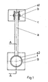
- Figure 1 shows a plan view,
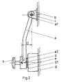
- Figure 2 shows an elevational side view and
- Figure 3 shows a partial section of the part with which the prehensile effect is obtained for holding the garment.
- The embodiment disclosed in the invention is comprised of a single hanging element which does not, in practice, preclude any number of such elements deemed appropriate from being grouped together. From this point of view, it can be considered as being a modular device wherein the module is a single hanger.
- Unlike the other aforementioned references, the invention presented (Figs. 1 and 2) consists in a physical pendulum whose centre of suspension "S" is produced by a support (b), which can be fixed to a vertical surface or wall, and by a horizontal axis (c) whereon the arm (a), which can swing freely, is articulated, by its upper end (a1).
- On the lower end of the arm (a) is a part which widens out (a2) in the form of a partially-open small dish (Figs. 1 and 2) wherein (Fig. 3) a permanent magnet (e) is housed which can freely swing at a certain angle "x" in both directions on a horizontal axis (d) joined to the small dish and parallel to the hanging of the pendulum; this magnet has a flat surface (e1) parallel to its axis of rotation, which faces towards the open part of the small dish (a2), from which it protrudes; inserted in the outer part of the closed part of the small dish is a handle or knob (f).
- The mass of the small dish (a2) added to that of the parts (d), (e) and (f) has a much larger value than the rest of the arm (a) which is why the centre of swing "P" of the physical pendulum (Fig. 2) will be considerably displaced towards the lower part thereof.
- At rest, the pendulum described hangs by its upper end (a1) from the axis (c) of the support (b) and at its lower end, the flat surface (e1) of the permanent magnet (e) rests on the flat surface (g1) of a part (g) of ferromagnetic material which can be attached to the same vertical surface or wall to which the support (b) is attached.
- The arm (a) has a swinging movement in its middle part and the surface (g1) of the part (g) is separate from the surface to which it is fastened for a certain distance, and thus when the surfaces (e1) and (g1) come into contact, the uprights which pass through the centres of suspension "S" and centres of swing "P" will not coincide, maintaining a certain separation "D" and the pendulum will not be able to reach its lowest position, with a horizontal gravitational force emerging which will push the part (e) against the part (g); and in view of the magnetic attraction between them, we can conclude that both forces, gravitational and magnetic, will contribute towards (e) and (g) remaining firmly joined together.
- The effectiveness of this join will be strengthened because the free swinging action of the part (e) on the axis (d) will automatically enable the surfaces (e1) and (g1) to have full coplanar contact, in the case described, which will increase the effectiveness of their mutual magnetic attraction.
- In accordance with the above, the invention will function as follows:
- It is assumed that the device described is at rest, with no hanging garments. In such circumstances, the parts (e) and (g) will be firmly joined together.
- Pulling the handle (f) will separate the parts (e) and (g) and the garment to be hung will be placed between them which, when the handle (f) is released, the garment will remain fixed by the friction action produced between itself and the surfaces (e1) and (g1) caused by the forces of attraction and gravitation that exist between the parts (e) and (g), which will have rounded edges so as not to damage the fabric of the garments.
- Positioning of the garment fabric hanging between the parts (e) and (g), not allowing them to be in direct contact, will weaken the magnetic force which draws them together, but will also increase the horizontal gravitational force which will push one against the other. Also contributing towards compensating for the reduction in the magnetic attraction caused by said positioning of the garment, is the ability of the part (e) to swing, which will enable the flat facing surfaces (e1) and (g1) to position themselves in a closely parallel position meaning that, first, the magnetic field produced by (e) will be used to the maximum and, second, the friction between said surfaces and the garment will be optimized, as well as ensuring that the right pressure is exerted against the garment so that its edges cannot damage the fabric.
- The invention is not strictly limited to the form of embodiment illustrated but may include any other variation of embodiment within the scope of the appended claim.
- The materials foreseen are those normally used in carrying out standard mechanical work.
Claims (1)
- IMPROVED WALL HANGER FOR NECK SCARVES AND LIGHTWEIGHT TEXTILES of the type which make use of the effect produced by two parts which are forced to press one against another; it may comprised modularly by a single hanger (or module) or by a set of several hangers; characterized in that each module comprises a physical pendulum where its pendular mass is mainly gathered in the free end of its arm (a) which is formed by a part which widens out in the form of a partially-open small dish (a2) that houses a magnet (e) which is permanent mounted on a horizontal axis (d) joined to the small dish (a2) and parallel to the hanging of the pendulum, whereon said magnet (e) can freely swing at a certain angle "x" in either direction; the magnet (e) has a flat surface (e1) parallel to its axis of rotation, which faces towards the open part of the small dish (a2) from which its protrudes; hanging and at rest, the lower part of the pendulum rests on a fixed part (g) of ferromagnetic material which has a flat surface (g1) facing that of the magnet (e) and parallel to the latter's axis of rotation; the arm (a) of the pendulum has a swinging action in its centre part which, together with the specific positioning of the ferromagnetic part (g), make the flat part (g1) of the latter and that of the magnet, when resting against one another, have coplanar contact before the pendulum reaches its lowest point, a position at which the above configuration would not let it reach; in the outer part of the closed part of the small dish (a2), a handle (f) or knob is inserted.
Applications Claiming Priority (2)
| Application Number | Priority Date | Filing Date | Title |
|---|---|---|---|
| ES200302565U | 2003-11-07 | ||
| ES200302565U ES1056037Y (en) | 2003-11-07 | 2003-11-07 | PERFECTED WALL HANGER, FOR LIGHT TEXTILES AND HANDSCAPES. |
Publications (2)
| Publication Number | Publication Date |
|---|---|
| EP1529467A1 EP1529467A1 (en) | 2005-05-11 |
| EP1529467B1 true EP1529467B1 (en) | 2006-06-21 |
Family
ID=31897193
Family Applications (1)
| Application Number | Title | Priority Date | Filing Date |
|---|---|---|---|
| EP04380218A Active EP1529467B1 (en) | 2003-11-07 | 2004-11-03 | Improved wall hanger, for neck scarves and lightweight textiles |
Country Status (5)
| Country | Link |
|---|---|
| US (1) | US20050109906A1 (en) |
| EP (1) | EP1529467B1 (en) |
| AT (1) | ATE330517T1 (en) |
| DE (1) | DE602004001313D1 (en) |
| ES (1) | ES1056037Y (en) |
Families Citing this family (3)
| Publication number | Priority date | Publication date | Assignee | Title |
|---|---|---|---|---|
| US20070194187A1 (en) * | 2005-12-08 | 2007-08-23 | Amron Scott L | Refrigerator magnet with clipping action |
| US20100252587A1 (en) * | 2009-04-02 | 2010-10-07 | Boles Alex R | Hookless clothes hanger system |
| US11122924B2 (en) * | 2019-08-27 | 2021-09-21 | Staybill, LLC | Bracket system for hats |
Family Cites Families (6)
| Publication number | Priority date | Publication date | Assignee | Title |
|---|---|---|---|---|
| US3823855A (en) * | 1973-01-31 | 1974-07-16 | H Dohring | Garment hanger |
| US5337459A (en) * | 1993-03-16 | 1994-08-16 | Security Tag Systems, Inc. | Magnetically releasable clamp |
| US5411231A (en) * | 1993-12-14 | 1995-05-02 | Buck; Richard F. | Magnetic attachment means of non-magnetic accessories to metal doors |
| US20020088909A1 (en) * | 2001-01-10 | 2002-07-11 | Ted Chen | Hanger assembly |
| JP4621409B2 (en) * | 2001-09-29 | 2011-01-26 | 龍之 河野 | Hanger with attachment and clothes hanging method using this hanger |
| US6769555B2 (en) * | 2002-02-01 | 2004-08-03 | Yvonne M. Brady | Clothing accessory hanging apparatus |
-
2003
- 2003-11-07 ES ES200302565U patent/ES1056037Y/en not_active Expired - Fee Related
-
2004
- 2004-11-03 AT AT04380218T patent/ATE330517T1/en not_active IP Right Cessation
- 2004-11-03 EP EP04380218A patent/EP1529467B1/en active Active
- 2004-11-03 DE DE602004001313T patent/DE602004001313D1/en active Active
- 2004-11-05 US US10/983,065 patent/US20050109906A1/en not_active Abandoned
Also Published As
| Publication number | Publication date |
|---|---|
| ES1056037U (en) | 2004-02-16 |
| ATE330517T1 (en) | 2006-07-15 |
| ES1056037Y (en) | 2004-06-01 |
| DE602004001313D1 (en) | 2006-08-03 |
| EP1529467A1 (en) | 2005-05-11 |
| US20050109906A1 (en) | 2005-05-26 |
Similar Documents
| Publication | Publication Date | Title |
|---|---|---|
| JP4621409B2 (en) | Hanger with attachment and clothes hanging method using this hanger | |
| US4632285A (en) | Convertible necktie and belt hanger apparatus | |
| EP1529467B1 (en) | Improved wall hanger, for neck scarves and lightweight textiles | |
| US2983014A (en) | Clothespin | |
| US3108723A (en) | Hat and garment holder | |
| US2946493A (en) | Garment hanger | |
| DE502004011401D1 (en) | DEVICE FOR MOUNTING A TRACK-ARMED CROSSBAR | |
| US2849168A (en) | Garment hanger units | |
| CN210013021U (en) | Easily hang anticreep clothes-horse | |
| US20120062087A1 (en) | Organizer for sorting jewelry by color or style | |
| US6227422B1 (en) | Mounting structure for neckties | |
| US892218A (en) | Display-rack for clothing. | |
| JP3066405U (en) | Jewelry decoration | |
| US2440024A (en) | Necktie holder | |
| GB2432523A (en) | Jewellery hanger for use on doors | |
| JP3041038U (en) | Trouser hanging hanger | |
| US797983A (en) | Hanger or supporting device. | |
| CN218922272U (en) | Multifunctional metal clothes hook | |
| CA2657822C (en) | Hanger saver | |
| US3089265A (en) | Trousers pressing device | |
| US2415642A (en) | Man's valet | |
| CN109881452B (en) | Easy-to-hang anti-drop clothes-horse | |
| US4930693A (en) | Body relief display device | |
| US1289658A (en) | Garment-display hanger. | |
| US7341767B1 (en) | System and method for displaying pom pons |
Legal Events
| Date | Code | Title | Description |
|---|---|---|---|
| PUAI | Public reference made under article 153(3) epc to a published international application that has entered the european phase |
Free format text: ORIGINAL CODE: 0009012 |
|
| AK | Designated contracting states |
Kind code of ref document: A1 Designated state(s): AT BE BG CH CY CZ DE DK EE ES FI FR GB GR HU IE IS IT LI LU MC NL PL PT RO SE SI SK TR |
|
| AX | Request for extension of the european patent |
Extension state: AL HR LT LV MK YU |
|
| GRAP | Despatch of communication of intention to grant a patent |
Free format text: ORIGINAL CODE: EPIDOSNIGR1 |
|
| 17P | Request for examination filed |
Effective date: 20051109 |
|
| AKX | Designation fees paid |
Designated state(s): AT BE BG CH CY CZ DE DK EE ES FI FR GB GR HU IE IS IT LI LU MC NL PL PT RO SE SI SK TR |
|
| GRAS | Grant fee paid |
Free format text: ORIGINAL CODE: EPIDOSNIGR3 |
|
| GRAA | (expected) grant |
Free format text: ORIGINAL CODE: 0009210 |
|
| AK | Designated contracting states |
Kind code of ref document: B1 Designated state(s): AT BE BG CH CY CZ DE DK EE ES FI FR GB GR HU IE IS IT LI LU MC NL PL PT RO SE SI SK TR |
|
| PG25 | Lapsed in a contracting state [announced via postgrant information from national office to epo] |
Ref country code: IT Free format text: LAPSE BECAUSE OF FAILURE TO SUBMIT A TRANSLATION OF THE DESCRIPTION OR TO PAY THE FEE WITHIN THE PRESCRIBED TIME-LIMIT;WARNING: LAPSES OF ITALIAN PATENTS WITH EFFECTIVE DATE BEFORE 2007 MAY HAVE OCCURRED AT ANY TIME BEFORE 2007. THE CORRECT EFFECTIVE DATE MAY BE DIFFERENT FROM THE ONE RECORDED. Effective date: 20060621 Ref country code: SI Free format text: LAPSE BECAUSE OF FAILURE TO SUBMIT A TRANSLATION OF THE DESCRIPTION OR TO PAY THE FEE WITHIN THE PRESCRIBED TIME-LIMIT Effective date: 20060621 Ref country code: AT Free format text: LAPSE BECAUSE OF FAILURE TO SUBMIT A TRANSLATION OF THE DESCRIPTION OR TO PAY THE FEE WITHIN THE PRESCRIBED TIME-LIMIT Effective date: 20060621 Ref country code: LI Free format text: LAPSE BECAUSE OF FAILURE TO SUBMIT A TRANSLATION OF THE DESCRIPTION OR TO PAY THE FEE WITHIN THE PRESCRIBED TIME-LIMIT Effective date: 20060621 Ref country code: SK Free format text: LAPSE BECAUSE OF FAILURE TO SUBMIT A TRANSLATION OF THE DESCRIPTION OR TO PAY THE FEE WITHIN THE PRESCRIBED TIME-LIMIT Effective date: 20060621 Ref country code: NL Free format text: LAPSE BECAUSE OF FAILURE TO SUBMIT A TRANSLATION OF THE DESCRIPTION OR TO PAY THE FEE WITHIN THE PRESCRIBED TIME-LIMIT Effective date: 20060621 Ref country code: RO Free format text: LAPSE BECAUSE OF FAILURE TO SUBMIT A TRANSLATION OF THE DESCRIPTION OR TO PAY THE FEE WITHIN THE PRESCRIBED TIME-LIMIT Effective date: 20060621 Ref country code: PL Free format text: LAPSE BECAUSE OF FAILURE TO SUBMIT A TRANSLATION OF THE DESCRIPTION OR TO PAY THE FEE WITHIN THE PRESCRIBED TIME-LIMIT Effective date: 20060621 Ref country code: CH Free format text: LAPSE BECAUSE OF FAILURE TO SUBMIT A TRANSLATION OF THE DESCRIPTION OR TO PAY THE FEE WITHIN THE PRESCRIBED TIME-LIMIT Effective date: 20060621 Ref country code: FI Free format text: LAPSE BECAUSE OF FAILURE TO SUBMIT A TRANSLATION OF THE DESCRIPTION OR TO PAY THE FEE WITHIN THE PRESCRIBED TIME-LIMIT Effective date: 20060621 Ref country code: BE Free format text: LAPSE BECAUSE OF FAILURE TO SUBMIT A TRANSLATION OF THE DESCRIPTION OR TO PAY THE FEE WITHIN THE PRESCRIBED TIME-LIMIT Effective date: 20060621 Ref country code: CZ Free format text: LAPSE BECAUSE OF FAILURE TO SUBMIT A TRANSLATION OF THE DESCRIPTION OR TO PAY THE FEE WITHIN THE PRESCRIBED TIME-LIMIT Effective date: 20060621 |
|
| REG | Reference to a national code |
Ref country code: GB Ref legal event code: FG4D |
|
| REG | Reference to a national code |
Ref country code: CH Ref legal event code: EP |
|
| REG | Reference to a national code |
Ref country code: IE Ref legal event code: FG4D |
|
| REF | Corresponds to: |
Ref document number: 602004001313 Country of ref document: DE Date of ref document: 20060803 Kind code of ref document: P |
|
| PG25 | Lapsed in a contracting state [announced via postgrant information from national office to epo] |
Ref country code: DK Free format text: LAPSE BECAUSE OF FAILURE TO SUBMIT A TRANSLATION OF THE DESCRIPTION OR TO PAY THE FEE WITHIN THE PRESCRIBED TIME-LIMIT Effective date: 20060921 Ref country code: SE Free format text: LAPSE BECAUSE OF FAILURE TO SUBMIT A TRANSLATION OF THE DESCRIPTION OR TO PAY THE FEE WITHIN THE PRESCRIBED TIME-LIMIT Effective date: 20060921 |
|
| PG25 | Lapsed in a contracting state [announced via postgrant information from national office to epo] |
Ref country code: DE Free format text: LAPSE BECAUSE OF FAILURE TO SUBMIT A TRANSLATION OF THE DESCRIPTION OR TO PAY THE FEE WITHIN THE PRESCRIBED TIME-LIMIT Effective date: 20060922 |
|
| PG25 | Lapsed in a contracting state [announced via postgrant information from national office to epo] |
Ref country code: ES Free format text: LAPSE BECAUSE OF FAILURE TO SUBMIT A TRANSLATION OF THE DESCRIPTION OR TO PAY THE FEE WITHIN THE PRESCRIBED TIME-LIMIT Effective date: 20061002 |
|
| PG25 | Lapsed in a contracting state [announced via postgrant information from national office to epo] |
Ref country code: IE Free format text: LAPSE BECAUSE OF NON-PAYMENT OF DUE FEES Effective date: 20061103 |
|
| PG25 | Lapsed in a contracting state [announced via postgrant information from national office to epo] |
Ref country code: PT Free format text: LAPSE BECAUSE OF FAILURE TO SUBMIT A TRANSLATION OF THE DESCRIPTION OR TO PAY THE FEE WITHIN THE PRESCRIBED TIME-LIMIT Effective date: 20061121 |
|
| PG25 | Lapsed in a contracting state [announced via postgrant information from national office to epo] |
Ref country code: MC Free format text: LAPSE BECAUSE OF NON-PAYMENT OF DUE FEES Effective date: 20061130 |
|
| NLV1 | Nl: lapsed or annulled due to failure to fulfill the requirements of art. 29p and 29m of the patents act | ||
| REG | Reference to a national code |
Ref country code: CH Ref legal event code: PL |
|
| PLBE | No opposition filed within time limit |
Free format text: ORIGINAL CODE: 0009261 |
|
| STAA | Information on the status of an ep patent application or granted ep patent |
Free format text: STATUS: NO OPPOSITION FILED WITHIN TIME LIMIT |
|
| EN | Fr: translation not filed | ||
| 26N | No opposition filed |
Effective date: 20070322 |
|
| PG25 | Lapsed in a contracting state [announced via postgrant information from national office to epo] |
Ref country code: FR Free format text: LAPSE BECAUSE OF FAILURE TO SUBMIT A TRANSLATION OF THE DESCRIPTION OR TO PAY THE FEE WITHIN THE PRESCRIBED TIME-LIMIT Effective date: 20070504 Ref country code: GR Free format text: LAPSE BECAUSE OF FAILURE TO SUBMIT A TRANSLATION OF THE DESCRIPTION OR TO PAY THE FEE WITHIN THE PRESCRIBED TIME-LIMIT Effective date: 20060922 |
|
| PG25 | Lapsed in a contracting state [announced via postgrant information from national office to epo] |
Ref country code: EE Free format text: LAPSE BECAUSE OF FAILURE TO SUBMIT A TRANSLATION OF THE DESCRIPTION OR TO PAY THE FEE WITHIN THE PRESCRIBED TIME-LIMIT Effective date: 20060621 Ref country code: BG Free format text: LAPSE BECAUSE OF FAILURE TO SUBMIT A TRANSLATION OF THE DESCRIPTION OR TO PAY THE FEE WITHIN THE PRESCRIBED TIME-LIMIT Effective date: 20060921 |
|
| PG25 | Lapsed in a contracting state [announced via postgrant information from national office to epo] |
Ref country code: LU Free format text: LAPSE BECAUSE OF NON-PAYMENT OF DUE FEES Effective date: 20061103 Ref country code: IS Free format text: LAPSE BECAUSE OF FAILURE TO SUBMIT A TRANSLATION OF THE DESCRIPTION OR TO PAY THE FEE WITHIN THE PRESCRIBED TIME-LIMIT Effective date: 20060621 Ref country code: HU Free format text: LAPSE BECAUSE OF FAILURE TO SUBMIT A TRANSLATION OF THE DESCRIPTION OR TO PAY THE FEE WITHIN THE PRESCRIBED TIME-LIMIT Effective date: 20061222 Ref country code: TR Free format text: LAPSE BECAUSE OF FAILURE TO SUBMIT A TRANSLATION OF THE DESCRIPTION OR TO PAY THE FEE WITHIN THE PRESCRIBED TIME-LIMIT Effective date: 20060621 |
|
| PG25 | Lapsed in a contracting state [announced via postgrant information from national office to epo] |
Ref country code: CY Free format text: LAPSE BECAUSE OF FAILURE TO SUBMIT A TRANSLATION OF THE DESCRIPTION OR TO PAY THE FEE WITHIN THE PRESCRIBED TIME-LIMIT Effective date: 20060621 Ref country code: FR Free format text: LAPSE BECAUSE OF FAILURE TO SUBMIT A TRANSLATION OF THE DESCRIPTION OR TO PAY THE FEE WITHIN THE PRESCRIBED TIME-LIMIT Effective date: 20060621 |
|
| GBPC | Gb: european patent ceased through non-payment of renewal fee |
Effective date: 20081103 |
|
| PG25 | Lapsed in a contracting state [announced via postgrant information from national office to epo] |
Ref country code: GB Free format text: LAPSE BECAUSE OF NON-PAYMENT OF DUE FEES Effective date: 20081103 |