EP1529379B1 - Protocole de creation et de gestion d'un reseau - Google Patents
Protocole de creation et de gestion d'un reseau Download PDFInfo
- Publication number
- EP1529379B1 EP1529379B1 EP03784356.2A EP03784356A EP1529379B1 EP 1529379 B1 EP1529379 B1 EP 1529379B1 EP 03784356 A EP03784356 A EP 03784356A EP 1529379 B1 EP1529379 B1 EP 1529379B1
- Authority
- EP
- European Patent Office
- Prior art keywords
- type
- description
- message
- networked
- device type
- Prior art date
- Legal status (The legal status is an assumption and is not a legal conclusion. Google has not performed a legal analysis and makes no representation as to the accuracy of the status listed.)
- Expired - Lifetime
Links
Images


Classifications
-
- H—ELECTRICITY
- H04—ELECTRIC COMMUNICATION TECHNIQUE
- H04L—TRANSMISSION OF DIGITAL INFORMATION, e.g. TELEGRAPHIC COMMUNICATION
- H04L12/00—Data switching networks
- H04L12/28—Data switching networks characterised by path configuration, e.g. LAN [Local Area Networks] or WAN [Wide Area Networks]
-
- G—PHYSICS
- G06—COMPUTING; CALCULATING OR COUNTING
- G06F—ELECTRIC DIGITAL DATA PROCESSING
- G06F40/00—Handling natural language data
- G06F40/10—Text processing
- G06F40/12—Use of codes for handling textual entities
- G06F40/14—Tree-structured documents
- G06F40/143—Markup, e.g. Standard Generalized Markup Language [SGML] or Document Type Definition [DTD]
-
- G—PHYSICS
- G06—COMPUTING; CALCULATING OR COUNTING
- G06F—ELECTRIC DIGITAL DATA PROCESSING
- G06F40/00—Handling natural language data
- G06F40/10—Text processing
- G06F40/12—Use of codes for handling textual entities
- G06F40/14—Tree-structured documents
- G06F40/146—Coding or compression of tree-structured data
-
- H—ELECTRICITY
- H04—ELECTRIC COMMUNICATION TECHNIQUE
- H04L—TRANSMISSION OF DIGITAL INFORMATION, e.g. TELEGRAPHIC COMMUNICATION
- H04L9/00—Cryptographic mechanisms or cryptographic arrangements for secret or secure communications; Network security protocols
- H04L9/40—Network security protocols
Definitions
- This invention relates to a network protocol, and in particular to implementations of the protocol.
- a prior art protocol for network management is universal plug and play (UPnP), which is very useful for internet applications where bandwidth, battery consumption, and to an extent cost, are not an issue.
- Implementations of the protocol in consumer electronics (CE) do exist, such as for example disclosed in US patent application No. US 2002/029256 A1 , but because of the extent of the protocol, such implementations impose a heavy load especially on the simplest devices that otherwise would require only minimal processing capability.
- PCT patent application No. WO99/57837 A2 discloses a method and system for performing a service on a home network.
- a system comprising: a plurality of networked devices each having a transceiver for sending and receiving network messages; at least one networked device arranged to send a simple device query message to other devices and to receive and interpret simple device description messages subsequently received from the other devices; at least one networked device arranged to send an extended device query message to other devices and to receive and
- each of the networked devices being arranged to respond to an incoming simple device query message from another of the devices by sending a simple device description message of defined length including a device type value representing the type of the device; and at least one of the networked devices is arranged to respond to an incoming extended device query message from another of the devices by sending an extended device description message.
- HUCL home uniform control language
- the Simple Device Description includes a small or moderate number of predetermined fields each field being of fixed length. In general, the same fields will be used for each message, although there may be some variation.
- a composite device may include an additional integer field including the number of sub-devices as explained below.
- the simple device description message is in the form of a token-compressed message compressed from a human-readable message format, the message including a device type value representing the type of the other device; the device type value being selected from a device type hierarchy having predetermined top level elements including a controller device type and a basic device type, and at least one further level of subsidiary device types depending from the basic device type and inheriting properties of higher level device types on which the subsidiary device type depends, but not including any further level of subsidiary device types depending from the controller device type.
- the underlying message format is a human readable format, such as XML.
- messages are passed between networked devices in compressed form.
- a networked device is nevertheless able to process such compressed messages, because the compression method used is token compression, which replaces common strings with tokens.
- the networked device can thus recognise the compressed tokens without decompression, at least enough to recognise a query requiring a response of a simple device description, and then respond with a simple device description.
- a networked device can be implemented with little overhead.
- the plurality of networked devices include at least one simple device without the capability to decompress messages and accordingly which interprets directly compressed messages and at least one complex device including a message decompression arrangement for decompressing the messages and a message interpreter for interpreting the decompressed messages.
- the invention relates to an individual networked device capable of responding to both simple and extended device description query message.
- a networked device including:
- the invention also relates to devices generating device query messages and processing the results.
- a networked device including a transceiver for sending and receiving messages:
- the invention also relates to the methods of operation of the devices of the second and third aspects.
- the invention relates to a method of operation of a networked device, including: sending a simple device description query message to one of the other devices requesting a simple device description; receiving from the other device a simple device description message of defined length including a device type value representing the type of the other device and a field indicating whether an extended device description is available; testing the simple device description message to determine whether an extended device description is available, and if so sending an extended device description query message to the other device requesting an extended device description from the other device; and receiving from the other device an extended device description of variable length.
- the invention relates to a method of operation of a networked device, including:
- the device type value may be selected from a device type hierarchy having predetermined top level elements including a controller device type and a basic device type, and at least one further level of subsidiary device types depending from the basic device type and inheriting properties of higher level device types on which the subsidiary device type depends, but not including any further level of subsidiary device types depending from the controller device type.
- a controller device preferably includes a control input, and controls other devices based on signals received on the control input. Further, the controller device may implement one or more ways of determining what devices the controller can control.
- One approach to deal with the lack of information when a device is a controller device type is for the controller device to have the functionality to respond to an incoming controller query message querying whether the controller can control a predetermined device type by responding with the lowest level of device type in the list of device types that can be controlled by the networked device that either is the predetermined device type or is a higher level device type from which the predetermined device type depends.
- the controller device can then send control signals selected from a predetermined list of control signals to other devices in accordance with signals received on the control input.
- the device may be a controlled device having a device type of the basic device type or a device type depending from the basic device type; the networked device having the capability of responding to basic device instructions sent by a controller, the instructions including at least a predetermined base set of instructions.
- the predetermined top level elements may include a composite device type with the functionality of a predetermined number of other device types, and arranged to respond to an incoming device query message requiring a simple device description by sending a simple device description including the device type as a composite device and the instantaneous number of other device types.
- the networked device may include a memory storing a predetermined simple device description message, wherein the description message is a message pre-compressed from a message in human readable form including a device type; a flag indicating if the sending device has an extended device description available; and a predetermined number of additional flags identifying a predetermined number of additional status settings.
- a suitable message is pre-stored and sent out when required.
- the invention also relates to a computer program for controlling a networked device.
- the system may include a number of simple devices, with simple functionality and no capability to decompress messages, and more complex devices that decompress messages to interpret them and operate on them.
- the more complex devices can have much more complex functionality, at the expense of increased overhead and processor power requirement.
- the protocol HUCL is a lightweight, low bandwidth control protocol primarily designed for wireless systems.
- the messaging format is based on XML, and messages are compressed prior to transmission.
- XML provides an extensible and scalable solution with the compression reducing the data sent, so reducing the amount of time the transmitter is on and consuming power.
- a light switch 2 and a light fitting 4 are provided.
- the light switch 2 has a physical rocker switch 6 operated by the user, together with an RF transceiver 8 and battery 10, together with control circuitry 12 and memory 14.
- the light fitting also has an RF transceiver 8 and memory 14, but is mains powered and has the control circuitry 20 to apply power to the light bulb 22.
- the light switch 2 is thus an example of a controller which has a control input 6 (the switch), whereas the light fitting is an example of a controlled device 4.
- the memory 14 in the controller includes a list 24 of device types that the controller can control, and control functions appertaining to the device types.
- the memory 14 in both controlled 4 and controller 2 devices also contains code 26 for causing the control circuitry to carry out the methods that will be described in more detail below.
- Figure 2 shows a representation of the software that resides on each of the devices in memory 14.
- the control application 30 communicates with the HUCL Software Stack 32 when certain events occur.
- the HUCL Software Stack 32 communicates with the RF Software Stack 34, and the RF Software Stack 34 will communicate back to the HUCL Software Stack 32 when certain events occur e.g. on receipt of data.
- the messages 36 are sent and received.
- the messages may be of a number of types, including a simple device description query message, or any of a number of other message types.
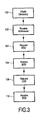
- the operation of the devices will now be described with reference to Figure 3 .
- the first phase in the operation of this pair of devices is for the switch to discover the address of the fitting. This is known as device discovery, and it is a requirement of the underlying RF transport stack that device discovery is either provided (in the RF Software Stack), or that it is possible to implement device discovery on top of the transport stack (in the lower layer of the HUCL Software Stack).
- the discovery process is initiated 100 by the Control Application (possibly as a result of some user interaction) by performing a call into the HUCL Software Stack requesting firstly the number of known devices, and then the network addresses of those devices. These device addresses are returned.
- the network addresses may be established in some other way.
- the end result of the device discovery phase is that the Control Application is supplied 102 with a list of addresses of all devices known by the RF Stack. At this point in the process the Control Application knows nothing more about each other device other than its address.
- the second phase in the pairing process is for the Control Application to gather information on the devices for which it has addresses. This information is called the device description.
- the control application does this by making a call into the HUCL Software Stack, passing the address of the device that it requires the device description from.
- the request for the simple device description is then passed 104 over the RF link to the destination device, so in the switch / fitting example described above the request is transmitted from the switch to the fitting.
- the HUCL Software Stack at the destination device makes a call in to the Control Application requesting the device description.
- the format of the description is defined. If not already in a compressed form the description is compressed before being transmitted back to the sender of the request.
- the HUCL Software Stack on the requesting device receives 106 the device description, it is passed up to the Control Application. At this point the application has some basic information about the device and can make the decision as to whether it wished to communicate further with this device.
- a design goal of HUCL is that it is suitable to operate on very simple devices, however the information necessary to fully describing a device is potentially quite complex.
- the list below shows the sort of information a device might want to provide as part of its description.
- the way in which this is overcome in HUCL is that the device description is split into two tiers of information.
- the first tier is a simplistic description of the device but identifying if further information is available. It does not contain any free text fields so the overall length of it is deterministic.
- the second tier of extended information is optional but provides additional information.
- the Simple Device Description message 230 includes as fields the device type 232, a field 238 to indicate if Extended Device Description available and other fields 236 identifying key information e.g. a flag to indicate if event subscription is available.
- Optional integer field 234 represents the number of sub-devices of a composite device.
- the skilled person will appreciate that the message 230 may also include a header and footer which are omitted for simplicity.
- the message will include compressed XML tokens which are likewise omitted for clarity.
- the fields of the Simple Device Description are all of fixed length, so that they can be dealt with readily without decompression.
- the controller device Control Application may issue a "GetExtendedDescription" request 108 back to the device.
- the HUCL Stack on the device receiving this request makes a Get Extended Description call into the Control Application requesting the Extended Device Description.
- the Extended Device Description is passed back to the HUCL Stack, and makes its way back to the Control Application on the device that requested it.
- the Extended Description is then returned 110 to the requesting device.
- the switch requests from the fitting its Simple Device Description. On receiving this it provides sufficient information such that the switch knows that it is talking to a light fitting that conforms to the standard fitting command set, it also knows that (for example) the fitting can't provide any Extended Device Description.
- the device type field 232 that identifies the type of the device, e.g. TV, DVD, Light Fitting etc.
- the Device Type field 232 will identify to the controller (requesting the Simple Device Description) the instruction set that the device conforms to.
- HUCL devices identify themselves simply by their type identifier, they do not then go on to send messages to describe how they are controlled; there is no 'runtime' service description concept in HUCL. If a device identifies itself as a light fitting then the command set that can be called on this device is identified in the HUCL specification for a Light Fitting type device.
- Top level elements 58 include in this example the controller device type 52, a basic device type 54 for controlled devices and an alarm device type 56.
- Subsidiary device types 68 depend from the basic device type. In the example, these include a TV device type 64, a dimmable light device type 62 and a PVR device 60.
- the Device Type Classification was to produce a system aims to allow a simple controller to identify whether it could control a device to the extent of the controllers' capabilities.
- a simple switch could be paired with a light fitting to turn on and off a light, but one might argue that the control functionality of the switch, that is its ability to turn a device on or off should be applicable to any device than can accept an on / off concept e.g. a TV, Heater, Printer.
- the switch One way in which this could be implemented is for the switch to have a list of all of the devices it knows how to control (turn On or Off), so when it requests the Simple Device Description for a device, it can look at the Device Type field in the returned description and determine if it is within its list of device types it knows how to control.
- the switch is a very simple device and it is undesirable for the application within it to have to hold a list of all possible devices that it could control, which would be quite large; secondly if a new type of device is created after the switch is produced (which can accept simple On Off functionality), then the switch will not have this new device type in its list, and will not believe it can control it i.e. it is not extensible.
- HUCL classifies devices in a hierarchical way, shown in Figure 4 .
- the Device Type field 232 ( Figure 15) identifies the device within the hierarchy and so even if new devices were created, as long as it is derived from an the appropriate point within the hierarchy, a simple switch would still know that it could control it to an extent.
- the key benefit of the Device Type hierarchy is that even if the controller has no knowledge of the specific device type itself, it can determine the device from which it is derived, of which it may have some knowledge and hence may be able to control the device to some lesser extent (from the perspective of the device).
- a light switch obtains the address of a device, it requests from this device the Simple Device Description; the Device Type field identifies the device as TV, but the switch does not recognise this as a device it knows about. However the switch can also establish from the description that it is a derivative of the 'Basic Device', which it does know about. The net result is that the switch can control the TV, to the extent of the controllers capabilities i.e. On and Off, despite knowing nothing about the device itself.
- the device could be a brand new category of device called an 'XYZ' invented long after the switch was manufactured, but so long as it is derived from a Basic Device the switch can still control it to an extent.
- the Device Type Hierarchy may have just two tiers, and controller and basic device top level elements, at least one further tier and/or top level element is desirable. This caters for devices that would not comply with the functionality shown above in the Basic Device that is devices that do not have basic 'Turn On' 'Turn Off functionality, e.g. an alarm.
- an 'Alarm' type device 56 has been shown in Figure 4 and understandably this 'Alarm' device does not want to implement the normal On /Off functions that devices that are derived from Basic Device must have; it therefore sits at the same top level 58 in the hierarchy as the Basic Device 54 itself.
- a second extension to the hierarchy is also shown in Figure 4 i.e. the Enhanced TV Device 66 below the normal TV Device 64.
- the Enhanced TV Device inherits all of the functionality of both the Basic Device 54 and the TV Device 64, but also includes some extended functionality that is not present in a normal TV.
- a regular TV remote control designed to operate a normal TV Device can operate the Enhanced TV Device to the level of a normal TV Device functionality, but can't control the extended functionality.
- the HUCL protocol accordingly provides an extensible mechanism for describing the Device Type and the devices above it from which it inherits functionality. Whilst the idea of a hierarchy of many layers might seem appealing, extending it beyond three or four levels will start to impact the size of the Simple Device Description.
- HUCL it is possible to request a device description from a controller as well as a controllable device.
- a controller device e.g. a switch
- a Simple Device Description that contains a Device Type of "Controller”.
- the controller device may also make available an Extended Device Description which provides further information such as the manufacturer, model number etc.
- Controller 52 there is no hierarchy of different controller type devices defined in the device type tree. The reason for this is again trying to keep the protocol and messages sizes small and simple. It might be felt that it would be possible to have different controller types derived from the basic Controller such as a Switch, TV Remote Control, PVR Remote Control, etc. However a problem would occur with intelligent controllers such as Universal Remote Controller that are capable of controlling a wide range of devices. To include all of the possible controller types in a simple device description would result in a potentially large message, which goes against the ideal of trying to make the initial Simple Device Description simple. To determine the exact capabilities of a controller device different mechanisms are employed.
- the first means of determining the capabilities of a controller device is by the Extended Device Description which is permitted on a controller device and may contain information such as the device name e.g. "Universal Remote Control" and whilst this is textual information and is not directly interpretable by application software, it can be presented to the user to assist in making an informed choice about a controller.
- the second means for a device to determine more about a controller is by querying it.
- querying is a powerful mechanism for drip-feeding information about a device that would otherwise, if supplied en-mass, overload the requestor.
- Each device of controller type provides a means for other devices to query 120 whether it is able to control a specific Device Type ( Figure 5 ).
- the device type passed in the query is the same field as is used in the Simple Device Description i.e. as defined in the Device Type Hierarchy.
- the controller returns 122 the level to which it can control the device, by returning the lowest device type in a list stored in the controller memory 14 that is the device type passed in the query or from which that device type depends. For example, a simple switch is queried whether it can control an Enhanced TV Device. Based on the hierarchy illustrated in Figure 4 above the reply is that it can control it to the level of Basic Device.
- the switch would typically itself know nothing about a device type of Enhanced TV Device, but since the Device Type also includes the inherited devices it would be able to identify the Basic Device and return this as the lowest hierarchically superior device type it is capable of controlling.
- the controller also implements an algorithm to determine if the switch can control a device type that is returned to it in a Simple Device Description ( Figure 6 ).
- a switch discovers the address of a device it asks 124 the device for its simple device description, on receiving this information 126 the switch tests 128 whether it can control a device of this type to any degree, which is the same question it needs to respond to as a result of the querying process 120.
- the result is that the two query processes 120, 122, 124, 126, 128 do not add too much to the complexity of the simple switch device. The same applies to other simple devices.
- a device may be a composition of a number of discrete devices all accessed via the same physical address e.g. all co-located on a single RF transceiver.
- Examples of this type of device are a bank of individually switchable lights controlled through a single RF transceiver, or a TV with integrated alarm clock where both components are remotely controllable again through the same transceiver.
- Figure 7 illustrates the discovery process.
- the switch initially obtains the addresses of all devices known by the underlying transport medium, this includes the single address of the four individually controllable lights.
- the switch issues 140 a Get Simple Description command to the light bank, and the question that arises is what should the reply be? If four device descriptions are returned then this would be four times as much data than the switch would be expecting to receive. Returning multiple Simple Device Descriptions is not very scalable, and would, for example cause problems if there were 20 lights in the lighting bank.
- the solution for this provided by HUCL is a specific Device Type for composite devices.
- the composite device returns 142 its Simple Device Description including in the Device Type field 232 its device type as a "Composite Device".
- the Simple Device Description also identifies in field 234 that there are, in this example, four embedded devices within this single device.
- the controller makes 144 further Get Simple Description requests to the composite device but addressing the requests to the specific embedded devices.
- the embedded devices return 146 their device descriptions.
- An example is a single device that consists of a lamp with integral switch, where the functionality of switch is exposed so as to be able to control other devices.
- This device when queried for its Simple Device Description exhibits itself as a composite device, but when queried further one embedded device would be found to be a controller, and the other a controllable i.e. a Light Device.
- a number of such devices could be configured in such a way that operating the switch on any one of the devices causes the lights to be turned On / Off on all the devices e.g. turning on any one table lamp in the lounge causes all the table lamps in the lounge to come on.
- VCR TV + video cassette recorder
- DVD DVD and VCR
- a Device consists of the core device plus zero or more sub-components, e.g. a TV Device 60 may for example consist of the TV Device 60 itself plus Tuner 64, Audio 66 and Display 68 sub-components (see Figure 8 ).
- a single device may have more than one instance of a sub-component e.g. a TV / VCR Combi Device may have two tuners 62, 64, one for the TV and one for the VCR (see Figure 9 ), as well as audio 66 and display 68 components.
- a TV / VCR Combi Device may have two tuners 62, 64, one for the TV and one for the VCR (see Figure 9 ), as well as audio 66 and display 68 components.
- Using a tagged compression technique on the XML takes the relatively verbose protocol back down in size towards that of a traditional pure binary-based protocol, with some additional overhead to retain the content structure.
- the HUCL specification defines that the messages is always transmitted through the transport medium in its compressed form.
- the application may operate directly on compressed messages, so eliminating the need on that device for the presence of the compression / de-compression software within the HUCL Software Stack.
- the application would store (as part of the application image in ROM) the simple device description in its pre-compressed form, it would have a parser for the compressed protocol messages that it receives which would be similar in nature to any other binary protocol parser; any response messages would also need to be stored in their compressed form.
- the simplest devices such as the light switch and light fitting example used throughout this section can be implemented with a reduced software stack, and given that the number of commands that a simple device would need to understand and send is relatively small (turn light on, turn light off, toggle, get current state, get device description etc.) the overhead on the application software is minimal.
- Figure 10 illustrates how the components that make up HUCL fit together. It will be appreciated that the components are software components recorded in memory.
- HUCL does not rely on a specific transport protocol (unlike for example TCP/IP) but instead sits directly on top of a transport stack 34.
- Different transport stacks 34 will by their nature offer differing services to applications and through differing API's; the HUCL Transport Adaption Layer 180 acts as a buffer to the specific transport layer.
- the Transport Adaption Layer 180 provides to the higher layers in the HUCL stack a consistent transport independent set of services. The requirements of this layer are defined in detail in the Protocol Specification.
- the messaging layer 182 provides the bulk of the functionality of the HUCL Software Stack. Applications communicate with this layer through .the HUCL API and it will perform the calls back in to the application when necessary (e.g. when data is received).
- the messaging layer 182 also handles any initial error reporting and if necessary acknowledgements. Message ID's and Transaction ID's used to check for missing messages and for coupling messages to replies are also handled fully by this layer.
- the Messaging layer 182 also makes use of the Compression / Decompression services 184 as and when a message needs to be compressed or decompressed. As discussed earlier an application deals exclusively with messages in their compressed form, no calls are made to these services and they can be removed from the runtime stack.
- the compression and decompression services provide the message layer with the means to convert the HUCL messages between their compressed and decompressed forms. It is possible for this component of the system to be absent in low-end devices where all data exchanges with the application are made with compressed messages.
- the application programming interface API 186 is the interface through which all applications communicate with the HUCL software Stack. Communication is bi-directional in that the HUCL stack will make asynchronous calls back to the application as a result of certain events occurring in the lower layers e.g. message received via the transport stack.
- HUCL is transport stack 34 independent, and what this means is that the HUCL messaging protocol can be built on top of a variety of transport stacks, both wired and wireless.
- HUCL is designed as a lightweight protocol it is therefore most suited to lightweight transport stacks as well such as the emerging Zigbee (802.15.4) standard, but it can sit equally well on top of TCP & UDP /IP which opens up a wide range of other protocols, both wired (e.g. Ethernet) and wireless (e.g. 802.11 b).
- wired e.g. Ethernet
- wireless e.g. 802.11 b
- a HUCL For a HUCL to be implemented on a transport stack 34 it must be possible to provide a number of services to the messaging layer of the HUCL stack. This means that these services can either be present in the transport stack itself or it must be possible to implement any missing services in the Transport Abstraction Layer of the HUCL stack. These services may cover aspects such as addressing, message delivery and device discovery (e.g. discovering the addresses of other devices on the network).
- the protocol itself is a document recorded on a medium 214, including the following information as shown in Figure 11 :
Landscapes
- Engineering & Computer Science (AREA)
- Theoretical Computer Science (AREA)
- Physics & Mathematics (AREA)
- General Engineering & Computer Science (AREA)
- Artificial Intelligence (AREA)
- Audiology, Speech & Language Pathology (AREA)
- Computational Linguistics (AREA)
- General Health & Medical Sciences (AREA)
- General Physics & Mathematics (AREA)
- Health & Medical Sciences (AREA)
- Signal Processing (AREA)
- Computer Networks & Wireless Communication (AREA)
- Computer Security & Cryptography (AREA)
- Selective Calling Equipment (AREA)
- Small-Scale Networks (AREA)
- Communication Control (AREA)
- Computer And Data Communications (AREA)
Claims (19)
- Procédé de fonctionnement d'un dispositif en réseau dans un réseau possédant au moins un autre dispositif, le procédé comprenant :l'envoi (104) d'un message d'interrogation de description de dispositif simple à au moins un autre dispositif demandant une description de dispositif simple ; etla réception (106), à partir de l'autre dispositif, d'un message de description de dispositif simple de longueur définie comprenant une valeur de type de dispositif représentant le type de l'autre dispositif et un champ indiquant si une description de dispositif approfondie est disponible ;le procédé étant caractérisé par :le test du message de description de dispositif simple pour déterminer si une description de dispositif approfondie est disponible ;l'envoi (108) d'un message d'interrogation de description de dispositif approfondie à l'autre dispositif demandant une description de dispositif approfondie à partir de l'autre dispositif ; etla réception (110), à partir de l'autre dispositif, d'une description de dispositif approfondie de longueur variable si la description de dispositif approfondie est disponible.
- Procédé selon la revendication 1, comprenant en outre l'établissement (102) de l'adresse de réseau d'un autre dispositif ou d'autres dispositifs avant l'étape de l'envoi (104) d'une description de dispositif simple à au moins un autre dispositif.
- Procédé selon la revendication 1 ou 2, dans lequel le message de description de dispositif simple (230) est sous forme de message compressé à jetons compressé à partir d'un format de message lisible par humain, le message comprenant une valeur de type de dispositif (232) représentant le type de l'autre dispositif ; la valeur de type de dispositif étant sélectionnée parmi une hiérarchie de type de dispositif possédant des éléments de haut niveau prédéterminés comprenant un type de dispositif d'organe de commande (52) et un type de dispositif de base (54), et au moins un niveau supplémentaire de types de dispositif subsidiaires dépendant du type de dispositif de base et héritant des propriétés de types de dispositif de niveau plus élevé dont le type de dispositif subsidiaire dépend, mais ne comprenant pas de niveau supplémentaire de types de dispositif subsidiaires dépendant du type de dispositif d'organe de commande.
- Procédé selon la revendication 3, dans lequel le dispositif en réseau est un dispositif d'organe de commande (2) comprenant une liste (24) de types de dispositif que l'organe de commande peut commander.
- Procédé selon la revendication 4, le procédé comprenant en outre la détermination que le dispositif en réseau peut commander un autre dispositif ou non en :déterminant le niveau le plus bas de type de dispositif qui est le type de dispositif de l'autre dispositif ou est un type de dispositif de niveau plus élevé dont le type de dispositif de l'autre dispositif dépend, dans la liste de types de dispositif qui peuvent être commandés par l'organe de commande, pour déterminer la mesure selon laquelle le dispositif en réseau peut commander l'autre dispositif.
- Procédé selon la revendication 5, comprenant en outre :la réception d'un message d'interrogation d'organe de commande à partir d'un autre dispositif comprenant une valeur de type de dispositif demandée pour demander si l'organe de commande est capable de commander un dispositif du type de dispositif demandé ; etla réponse avec un message de réponse d'organe de commande comprenant une valeur de type de dispositif représentant le niveau le plus bas de type de dispositif dans la liste de types de dispositif qui est le type de dispositif demandé ou est un type de dispositif de niveau plus élevé dont le type de dispositif demandé dépend.
- Procédé selon la revendication 2 dans lequel les éléments de haut niveau prédéterminés dans la hiérarchie de type de dispositif comprennent en outre un type de dispositif composite, et le dispositif en réseau est du type de dispositif composite possédant la fonctionnalité d'un nombre entier d'autres dispositifs, le procédé comprenant en outre :la réponse à un message reçu d'interrogation de description de dispositif simple en envoyant un message de description de dispositif simple (230) comprenant la valeur de type de dispositif (232) représentant le dispositif en tant que dispositif composite et en outre un nombre entier de sous-dispositifs qui est le nombre (234) d'autres dispositifs.
- Procédé de fonctionnement d'un dispositif en réseau, comprenant :la réception (104) d'un message d'interrogation de description de dispositif simple à partir d'un des autres dispositifs demandant une description de dispositif simple ;l'envoi (106), à l'autre dispositif, d'un message de description de dispositif simple de longueur définie comprenant une valeur de type de dispositif représentant le type du dispositif en réseau et un champ indiquant si une description de dispositif approfondie est disponible ;la réception (108) d'un message d'interrogation de description de dispositif approfondie à partir de l'autre dispositif demandant une description de dispositif approfondie à partir du dispositif en réseau ; etl'envoi (110), à l'autre dispositif, d'une description de dispositif approfondie de longueur variable si la description de dispositif approfondie est disponible.
- Dispositif en réseau, comprenant :un émetteur-récepteur (8) pour envoyer et recevoir des messages ; etun gestionnaire de message (26, 182) agencé pour réaliser l'étape de :lors de la réception (104) d'un message d'interrogation de description de dispositif simple à partir d'un des autres dispositifs, l'envoi (106), à l'autre dispositif, d'un message de description de dispositif simple de longueur définie comprenant une valeur de type de dispositif représentant le type du dispositif en réseau, et un champ indiquant si une description de dispositif approfondie est disponible ; et étant caractérisé par :lors de la réception (108) d'un message d'interrogation de description de dispositif approfondie à partir d'un autre dispositif, l'envoi (110), à l'autre dispositif, d'une description de dispositif approfondie de longueur variable si la description de dispositif approfondie est disponible.
- Dispositif en réseau selon la revendication 9, dans lequel le message de description de dispositif simple (230) est sous forme de message compressé à jetons compressé à partir d'un format de message lisible par humain, le message comprenant une valeur de type de dispositif (232) représentant le type de l'autre dispositif ;
la valeur de type de dispositif étant sélectionnée parmi une hiérarchie de type de dispositif possédant des éléments de haut niveau prédéterminés comprenant un type de dispositif d'organe de commande (52) et un type de dispositif de base (54), et au moins un niveau supplémentaire de types de dispositif subsidiaires dépendant du type de dispositif de base et héritant des propriétés de types de dispositif de niveau plus élevé dont le type de dispositif subsidiaire dépend, mais ne comprenant pas de niveau supplémentaire de types de dispositif subsidiaires dépendant du type de dispositif d'organe de commande. - Dispositif en réseau, comprenant :un émetteur-récepteur (8) pour envoyer et recevoir des messages ;un gestionnaire de message (26, 182) agencé pour réaliser les étapes de :l'envoi d'un message d'interrogation de description de dispositif simple à un autre dispositif demandant une description de dispositif simple ; etla réception, à partir de l'autre dispositif, d'un message de description de dispositif simple de longueur fixe comprenant une valeur de type de dispositif représentant le type de l'autre dispositif et un champ indiquant si une description de dispositif approfondie est disponible ;et caractérisé en ce qu'il est en outre agencé pour réaliser les étapes de :le test du message de description de dispositif simple pour déterminer si une description de dispositif approfondie est disponible ;l'envoi d'un message d'interrogation de description de dispositif approfondie à l'autre dispositif demandant une description de dispositif approfondie à partir de l'autre dispositif ; etla réception, à partir de l'autre dispositif, d'une description de dispositif approfondie de longueur variable, si la description de dispositif approfondie est disponible.
- Dispositif en réseau selon la revendication 11, dans lequel le message de description de dispositif simple (230) est sous forme de message compressé à jetons compressé à partir d'un format de message lisible par humain, le message comprenant une valeur de type de dispositif (232) représentant le type de l'autre dispositif ;
la valeur de type de dispositif étant sélectionnée parmi une hiérarchie de type de dispositif possédant des éléments de haut niveau prédéterminés comprenant un type de dispositif d'organe de commande (52) et un type de dispositif de base (54), et au moins un niveau supplémentaire de types de dispositif subsidiaires dépendant du type de dispositif de base et héritant des propriétés de types de dispositif de niveau plus élevé dont le type de dispositif subsidiaire dépend, mais ne comprenant pas de niveau supplémentaire de types de dispositif subsidiaires dépendant du type de dispositif d'organe de commande. - Dispositif en réseau selon la revendication 12, dans lequel le dispositif en réseau comporte le type de dispositif d'organe de commande,
dans lequel le dispositif en réseau comprend une liste de types de dispositif qui peuvent être commandés par le dispositif en réseau, pour que le dispositif en réseau puisse déterminer la mesure selon laquelle le dispositif en réseau peut commander un autre dispositif en déterminant le niveau le plus bas de type de dispositif qui est le type de dispositif de l'autre dispositif ou est un type de dispositif de niveau plus élevé dont le type de dispositif de l'autre dispositif dépend, dans la liste de types de dispositif qui peuvent être commandés par l'organe de commande. - Dispositif en réseau selon la revendication 13, dans lequel le gestionnaire de message est agencé :pour recevoir un message d'interrogation d'organe de commande à partir d'un autre dispositif comprenant une valeur de type de dispositif demandée pour demander si l'organe de commande est capable de commander un dispositif du type de dispositif demandé ; etpour répondre avec un message de réponse d'organe de commande comprenant une valeur de type de dispositif représentant le niveau le plus bas de type de dispositif dans la liste de types de dispositif qui est le type de dispositif demandé ou est un type de dispositif de niveau plus élevé dont le type de dispositif demandé dépend.
- Système, comprenant un dispositif en réseau selon la revendication 9 et un dispositif en réseau selon la revendication 11.
- Système selon la revendication 15, dans lequel la pluralité de dispositifs en réseau comprennent au moins un dispositif simple sans la capacité de décompresser des messages et d'interpréter des messages directement compressés et au moins un dispositif complexe comprenant un agencement de décompression de message (184) pour décompresser les messages et un interpréteur de message pour interpréter les messages décompressés.
- Système selon la revendication 15 ou 16, dans lequel les éléments de haut niveau prédéterminés comprennent en outre un type de dispositif composite ;
le système comprend au moins un dispositif en réseau du type de dispositif composite possédant la fonctionnalité d'un nombre prédéterminé d'autres dispositifs, le nombre prédéterminé étant un nombre entier supérieur ou égal à 2 ; et
chacun de l'au moins un dispositif en réseau du type de dispositif composite répond à un message entrant d'interrogation de dispositif nécessitant une description de dispositif simple en envoyant une description de dispositif simple (230) comprenant le type de dispositif (232) en tant que dispositif composite et un nombre de sous-dispositifs (234) représentant le nombre prédéterminé d'autres dispositifs. - Programme d'ordinateur pour commander un dispositif en réseau, le programme d'ordinateur étant agencé pour entraîner la réalisation, par le dispositif en réseau, des étapes d'un procédé selon une quelconque des revendications 1 à 8.
- Programme d'ordinateur selon la revendication 18 enregistré sur un support de données (14).
Applications Claiming Priority (5)
| Application Number | Priority Date | Filing Date | Title |
|---|---|---|---|
| GBGB0218174.1A GB0218174D0 (en) | 2002-08-06 | 2002-08-06 | A network establishment and management protocol |
| GB0218174 | 2002-08-06 | ||
| GB0309401 | 2003-04-25 | ||
| GB0309401 | 2003-04-25 | ||
| PCT/IB2003/003307 WO2004015956A2 (fr) | 2002-08-06 | 2003-07-24 | Protocole de creation et de gestion d'un reseau |
Publications (2)
| Publication Number | Publication Date |
|---|---|
| EP1529379A2 EP1529379A2 (fr) | 2005-05-11 |
| EP1529379B1 true EP1529379B1 (fr) | 2013-07-17 |
Family
ID=31716913
Family Applications (1)
| Application Number | Title | Priority Date | Filing Date |
|---|---|---|---|
| EP03784356.2A Expired - Lifetime EP1529379B1 (fr) | 2002-08-06 | 2003-07-24 | Protocole de creation et de gestion d'un reseau |
Country Status (9)
| Country | Link |
|---|---|
| US (2) | US8078742B2 (fr) |
| EP (1) | EP1529379B1 (fr) |
| JP (1) | JP2005535247A (fr) |
| KR (1) | KR101058065B1 (fr) |
| CN (1) | CN100525223C (fr) |
| AU (1) | AU2003249528A1 (fr) |
| DK (1) | DK1529379T3 (fr) |
| ES (1) | ES2428356T3 (fr) |
| WO (1) | WO2004015956A2 (fr) |
Families Citing this family (8)
| Publication number | Priority date | Publication date | Assignee | Title |
|---|---|---|---|---|
| GB0411528D0 (en) * | 2004-05-24 | 2004-06-23 | Koninkl Philips Electronics Nv | Device abstraction layer for local networking system |
| KR100702516B1 (ko) * | 2006-04-07 | 2007-04-02 | 삼성전자주식회사 | 디.엘.엔.에이 네트워크를 이용한 데이터 저장 방법 및 그장치 |
| US20120311070A1 (en) * | 2011-05-31 | 2012-12-06 | Fanhattan Llc | Intelligent application adapted to multiple devices |
| PT2944104T (pt) | 2012-11-12 | 2021-09-15 | Empi Inc | Sistemas e métodos para emparelhamento sem fios e comunicação para eletroestimulação |
| US10313831B2 (en) | 2014-05-09 | 2019-06-04 | Futurewei Technologies, Inc. | Extensible solution for device to device discovery message size |
| US10623244B2 (en) * | 2014-12-19 | 2020-04-14 | Emerson Process Management Lllp | Data transfer on an industrial process network |
| KR102442428B1 (ko) * | 2015-09-24 | 2022-09-14 | 삼성전자주식회사 | 다바이스의 액세스 토큰 발급 방법 및 이를 지원하는 장치 |
| CN111061207A (zh) * | 2019-12-25 | 2020-04-24 | 湖南舞龙软件开发有限公司 | 一种基于数据驱动的设备描述方法 |
Family Cites Families (12)
| Publication number | Priority date | Publication date | Assignee | Title |
|---|---|---|---|---|
| EP0990349A1 (fr) * | 1997-06-16 | 2000-04-05 | Telefonaktiebolaget Lm Ericsson | Systeme de gestion de performances en telecommunications |
| US5991713A (en) * | 1997-11-26 | 1999-11-23 | International Business Machines Corp. | Efficient method for compressing, storing, searching and transmitting natural language text |
| CN1115824C (zh) | 1998-05-07 | 2003-07-23 | 三星电子株式会社 | 网络中的装置对装置命令与控制的方法和系统 |
| US7603408B1 (en) * | 1999-05-10 | 2009-10-13 | 3Com Corporation | Method and system for network management |
| US6910068B2 (en) | 1999-06-11 | 2005-06-21 | Microsoft Corporation | XML-based template language for devices and services |
| US7171475B2 (en) * | 2000-12-01 | 2007-01-30 | Microsoft Corporation | Peer networking host framework and hosting API |
| US6832273B2 (en) * | 2000-12-21 | 2004-12-14 | Microsoft Corporation | System and method to specify extended configuration descriptor information in USB devices |
| WO2003021978A1 (fr) * | 2001-08-10 | 2003-03-13 | Strix Systems, Inc. | Liaison virtuelle faisant appel a un dispositif sans fil |
| US7299304B2 (en) * | 2001-11-20 | 2007-11-20 | Intel Corporation | Method and architecture to support interaction between a host computer and remote devices |
| US7058734B2 (en) * | 2002-02-25 | 2006-06-06 | Hewlett-Packard Development Company, Lp. | Variable-function or multi-function apparatus and methods |
| US6930958B2 (en) * | 2002-04-02 | 2005-08-16 | Nate Goergen | Method and apparatus for synchronizing timekeeping devices |
| US8312132B2 (en) * | 2004-08-20 | 2012-11-13 | Core Wireless Licensing S.A.R.L. | Context data in UPNP service information |
-
2003
- 2003-07-24 JP JP2004527168A patent/JP2005535247A/ja active Pending
- 2003-07-24 US US10/523,377 patent/US8078742B2/en active Active
- 2003-07-24 AU AU2003249528A patent/AU2003249528A1/en not_active Abandoned
- 2003-07-24 CN CNB038188570A patent/CN100525223C/zh not_active Expired - Lifetime
- 2003-07-24 ES ES03784356T patent/ES2428356T3/es not_active Expired - Lifetime
- 2003-07-24 WO PCT/IB2003/003307 patent/WO2004015956A2/fr active Application Filing
- 2003-07-24 KR KR1020057002136A patent/KR101058065B1/ko active IP Right Grant
- 2003-07-24 DK DK03784356.2T patent/DK1529379T3/da active
- 2003-07-24 EP EP03784356.2A patent/EP1529379B1/fr not_active Expired - Lifetime
-
2011
- 2011-11-09 US US13/292,211 patent/US8943213B2/en active Active
Also Published As
| Publication number | Publication date |
|---|---|
| CN1675886A (zh) | 2005-09-28 |
| US8078742B2 (en) | 2011-12-13 |
| KR101058065B1 (ko) | 2011-08-22 |
| CN100525223C (zh) | 2009-08-05 |
| US20120059898A1 (en) | 2012-03-08 |
| WO2004015956A3 (fr) | 2004-09-16 |
| KR20050084796A (ko) | 2005-08-29 |
| DK1529379T3 (da) | 2013-10-14 |
| US20060026291A1 (en) | 2006-02-02 |
| AU2003249528A1 (en) | 2004-02-25 |
| ES2428356T3 (es) | 2013-11-07 |
| US8943213B2 (en) | 2015-01-27 |
| AU2003249528A8 (en) | 2004-02-25 |
| JP2005535247A (ja) | 2005-11-17 |
| EP1529379A2 (fr) | 2005-05-11 |
| WO2004015956A2 (fr) | 2004-02-19 |
Similar Documents
| Publication | Publication Date | Title |
|---|---|---|
| US8943213B2 (en) | Network establishment and management protocol | |
| US8874689B2 (en) | Network establishment and management protocol | |
| US7194689B2 (en) | Generic user control point tool for universal plug and play (UPnP) devices | |
| US7191236B2 (en) | Transparent telecommunications system and apparatus | |
| US7089307B2 (en) | Synchronization of controlled device state using state table and eventing in data-driven remote device control model | |
| US7602756B2 (en) | Dynamic self-configuration for ad hoc peer networking | |
| CN1943171B (zh) | 用于控制分布式站的网络中的设备的方法和网络站 | |
| US20060031570A1 (en) | Network establishment and management protocol | |
| CN100521636C (zh) | 在URI中嵌入UPnP AV媒体服务器的对象ID | |
| EP2278456A1 (fr) | Appareil et procédé de gestion d'interface utilisateur | |
| US20020052966A1 (en) | Service discovery protocol server | |
| JP2002009807A (ja) | ネットワークサーバおよびネットワークシステム | |
| US20060031192A1 (en) | Network establishment and management protocol |
Legal Events
| Date | Code | Title | Description |
|---|---|---|---|
| PUAI | Public reference made under article 153(3) epc to a published international application that has entered the european phase |
Free format text: ORIGINAL CODE: 0009012 |
|
| 17P | Request for examination filed |
Effective date: 20050316 |
|
| AK | Designated contracting states |
Kind code of ref document: A2 Designated state(s): AT BE BG CH CY CZ DE DK EE ES FI FR GB GR HU IE IT LI LU MC NL PT RO SE SI SK TR |
|
| AX | Request for extension of the european patent |
Extension state: AL LT LV MK |
|
| DAX | Request for extension of the european patent (deleted) | ||
| 17Q | First examination report despatched |
Effective date: 20090504 |
|
| GRAP | Despatch of communication of intention to grant a patent |
Free format text: ORIGINAL CODE: EPIDOSNIGR1 |
|
| RIN1 | Information on inventor provided before grant (corrected) |
Inventor name: BLACKWELL, ROBIN A., C/O PHILIPS INTELLECTUAL Inventor name: HANKIN, NEIL A., C/O PHILIPS INTELLECTUAL Inventor name: LANIGAN, PETER J., C/O PHILIPS INTELLECTUAL Inventor name: RUDLAND, PHILIP A., C/O PHILIPS INTELLECTUAL Inventor name: SHEPHERD, NICOLL B., C/O PHILIPS INTELLECTUAL |
|
| GRAS | Grant fee paid |
Free format text: ORIGINAL CODE: EPIDOSNIGR3 |
|
| GRAA | (expected) grant |
Free format text: ORIGINAL CODE: 0009210 |
|
| AK | Designated contracting states |
Kind code of ref document: B1 Designated state(s): AT BE BG CH CY CZ DE DK EE ES FI FR GB GR HU IE IT LI LU MC NL PT RO SE SI SK TR |
|
| REG | Reference to a national code |
Ref country code: GB Ref legal event code: FG4D |
|
| REG | Reference to a national code |
Ref country code: CH Ref legal event code: EP |
|
| REG | Reference to a national code |
Ref country code: IE Ref legal event code: FG4D |
|
| REG | Reference to a national code |
Ref country code: AT Ref legal event code: REF Ref document number: 622768 Country of ref document: AT Kind code of ref document: T Effective date: 20130815 |
|
| REG | Reference to a national code |
Ref country code: CH Ref legal event code: PFA Owner name: KONINKLIJKE PHILIPS N.V., NL Free format text: FORMER OWNER: KONINKLIJKE PHILIPS ELECTRONICS N.V., NL |
|
| REG | Reference to a national code |
Ref country code: DE Ref legal event code: R096 Ref document number: 60344526 Country of ref document: DE Effective date: 20130912 |
|
| RAP2 | Party data changed (patent owner data changed or rights of a patent transferred) |
Owner name: KONINKLIJKE PHILIPS N.V. |
|
| REG | Reference to a national code |
Ref country code: NL Ref legal event code: T3 |
|
| REG | Reference to a national code |
Ref country code: DK Ref legal event code: T3 Effective date: 20131009 Ref country code: DK Ref legal event code: T3 |
|
| REG | Reference to a national code |
Ref country code: CH Ref legal event code: NV Representative=s name: WAGNER PATENT AG, CH |
|
| REG | Reference to a national code |
Ref country code: SE Ref legal event code: TRGR |
|
| REG | Reference to a national code |
Ref country code: ES Ref legal event code: FG2A Ref document number: 2428356 Country of ref document: ES Kind code of ref document: T3 Effective date: 20131107 |
|
| PG25 | Lapsed in a contracting state [announced via postgrant information from national office to epo] |
Ref country code: PT Free format text: LAPSE BECAUSE OF FAILURE TO SUBMIT A TRANSLATION OF THE DESCRIPTION OR TO PAY THE FEE WITHIN THE PRESCRIBED TIME-LIMIT Effective date: 20131118 Ref country code: CY Free format text: LAPSE BECAUSE OF FAILURE TO SUBMIT A TRANSLATION OF THE DESCRIPTION OR TO PAY THE FEE WITHIN THE PRESCRIBED TIME-LIMIT Effective date: 20130703 |
|
| PGFP | Annual fee paid to national office [announced via postgrant information from national office to epo] |
Ref country code: BE Payment date: 20130830 Year of fee payment: 11 |
|
| REG | Reference to a national code |
Ref country code: ES Ref legal event code: PC2A Owner name: KONINKLIJKE PHILIPS N.V. Effective date: 20140220 |
|
| PG25 | Lapsed in a contracting state [announced via postgrant information from national office to epo] |
Ref country code: SI Free format text: LAPSE BECAUSE OF FAILURE TO SUBMIT A TRANSLATION OF THE DESCRIPTION OR TO PAY THE FEE WITHIN THE PRESCRIBED TIME-LIMIT Effective date: 20130717 Ref country code: FI Free format text: LAPSE BECAUSE OF FAILURE TO SUBMIT A TRANSLATION OF THE DESCRIPTION OR TO PAY THE FEE WITHIN THE PRESCRIBED TIME-LIMIT Effective date: 20130717 Ref country code: GR Free format text: LAPSE BECAUSE OF FAILURE TO SUBMIT A TRANSLATION OF THE DESCRIPTION OR TO PAY THE FEE WITHIN THE PRESCRIBED TIME-LIMIT Effective date: 20131018 |
|
| REG | Reference to a national code |
Ref country code: CH Ref legal event code: PCAR Free format text: NEW ADDRESS: BAECHERSTRASSE 9, 8832 WOLLERAU (CH) |
|
| PG25 | Lapsed in a contracting state [announced via postgrant information from national office to epo] |
Ref country code: CY Free format text: LAPSE BECAUSE OF FAILURE TO SUBMIT A TRANSLATION OF THE DESCRIPTION OR TO PAY THE FEE WITHIN THE PRESCRIBED TIME-LIMIT Effective date: 20130717 |
|
| REG | Reference to a national code |
Ref country code: IE Ref legal event code: MM4A |
|
| PG25 | Lapsed in a contracting state [announced via postgrant information from national office to epo] |
Ref country code: MC Free format text: LAPSE BECAUSE OF FAILURE TO SUBMIT A TRANSLATION OF THE DESCRIPTION OR TO PAY THE FEE WITHIN THE PRESCRIBED TIME-LIMIT Effective date: 20130717 Ref country code: EE Free format text: LAPSE BECAUSE OF FAILURE TO SUBMIT A TRANSLATION OF THE DESCRIPTION OR TO PAY THE FEE WITHIN THE PRESCRIBED TIME-LIMIT Effective date: 20130717 Ref country code: SK Free format text: LAPSE BECAUSE OF FAILURE TO SUBMIT A TRANSLATION OF THE DESCRIPTION OR TO PAY THE FEE WITHIN THE PRESCRIBED TIME-LIMIT Effective date: 20130717 Ref country code: CZ Free format text: LAPSE BECAUSE OF FAILURE TO SUBMIT A TRANSLATION OF THE DESCRIPTION OR TO PAY THE FEE WITHIN THE PRESCRIBED TIME-LIMIT Effective date: 20130717 Ref country code: RO Free format text: LAPSE BECAUSE OF FAILURE TO SUBMIT A TRANSLATION OF THE DESCRIPTION OR TO PAY THE FEE WITHIN THE PRESCRIBED TIME-LIMIT Effective date: 20130717 |
|
| REG | Reference to a national code |
Ref country code: DE Ref legal event code: R081 Ref document number: 60344526 Country of ref document: DE Owner name: KONINKLIJKE PHILIPS N.V., NL Free format text: FORMER OWNER: KONINKLIJKE PHILIPS ELECTRONICS N.V., EINDHOVEN, NL Effective date: 20130719 Ref country code: DE Ref legal event code: R081 Ref document number: 60344526 Country of ref document: DE Owner name: KONINKLIJKE PHILIPS N.V., NL Free format text: FORMER OWNER: KONINKLIJKE PHILIPS ELECTRONICS N.V., EINDHOVEN, NL Effective date: 20140328 |
|
| PLBE | No opposition filed within time limit |
Free format text: ORIGINAL CODE: 0009261 |
|
| STAA | Information on the status of an ep patent application or granted ep patent |
Free format text: STATUS: NO OPPOSITION FILED WITHIN TIME LIMIT |
|
| 26N | No opposition filed |
Effective date: 20140422 |
|
| PG25 | Lapsed in a contracting state [announced via postgrant information from national office to epo] |
Ref country code: IE Free format text: LAPSE BECAUSE OF NON-PAYMENT OF DUE FEES Effective date: 20130724 |
|
| REG | Reference to a national code |
Ref country code: DE Ref legal event code: R097 Ref document number: 60344526 Country of ref document: DE Effective date: 20140422 |
|
| PG25 | Lapsed in a contracting state [announced via postgrant information from national office to epo] |
Ref country code: HU Free format text: LAPSE BECAUSE OF FAILURE TO SUBMIT A TRANSLATION OF THE DESCRIPTION OR TO PAY THE FEE WITHIN THE PRESCRIBED TIME-LIMIT; INVALID AB INITIO Effective date: 20030724 Ref country code: LU Free format text: LAPSE BECAUSE OF NON-PAYMENT OF DUE FEES Effective date: 20130724 Ref country code: BG Free format text: LAPSE BECAUSE OF FAILURE TO SUBMIT A TRANSLATION OF THE DESCRIPTION OR TO PAY THE FEE WITHIN THE PRESCRIBED TIME-LIMIT Effective date: 20130717 |
|
| REG | Reference to a national code |
Ref country code: FR Ref legal event code: PLFP Year of fee payment: 14 |
|
| PG25 | Lapsed in a contracting state [announced via postgrant information from national office to epo] |
Ref country code: BE Free format text: THE PATENT HAS BEEN ANNULLED BY A DECISION OF A NATIONAL AUTHORITY Effective date: 20130717 |
|
| REG | Reference to a national code |
Ref country code: FR Ref legal event code: PLFP Year of fee payment: 15 |
|
| REG | Reference to a national code |
Ref country code: FR Ref legal event code: PLFP Year of fee payment: 16 |
|
| PGFP | Annual fee paid to national office [announced via postgrant information from national office to epo] |
Ref country code: NL Payment date: 20220726 Year of fee payment: 20 |
|
| PGFP | Annual fee paid to national office [announced via postgrant information from national office to epo] |
Ref country code: TR Payment date: 20220714 Year of fee payment: 20 Ref country code: SE Payment date: 20220722 Year of fee payment: 20 Ref country code: IT Payment date: 20220725 Year of fee payment: 20 Ref country code: GB Payment date: 20220719 Year of fee payment: 20 Ref country code: ES Payment date: 20220817 Year of fee payment: 20 Ref country code: DK Payment date: 20220722 Year of fee payment: 20 Ref country code: DE Payment date: 20220628 Year of fee payment: 20 Ref country code: AT Payment date: 20220719 Year of fee payment: 20 |
|
| PGFP | Annual fee paid to national office [announced via postgrant information from national office to epo] |
Ref country code: FR Payment date: 20220725 Year of fee payment: 20 |
|
| PGFP | Annual fee paid to national office [announced via postgrant information from national office to epo] |
Ref country code: CH Payment date: 20220726 Year of fee payment: 20 |
|
| REG | Reference to a national code |
Ref country code: DE Ref legal event code: R071 Ref document number: 60344526 Country of ref document: DE |
|
| REG | Reference to a national code |
Ref country code: NL Ref legal event code: MK Effective date: 20230723 |
|
| REG | Reference to a national code |
Ref country code: CH Ref legal event code: PL Ref country code: ES Ref legal event code: FD2A Effective date: 20230731 Ref country code: DK Ref legal event code: EUP Expiry date: 20230724 |
|
| REG | Reference to a national code |
Ref country code: GB Ref legal event code: PE20 Expiry date: 20230723 |
|
| REG | Reference to a national code |
Ref country code: SE Ref legal event code: EUG |
|
| REG | Reference to a national code |
Ref country code: AT Ref legal event code: MK07 Ref document number: 622768 Country of ref document: AT Kind code of ref document: T Effective date: 20230724 |
|
| PG25 | Lapsed in a contracting state [announced via postgrant information from national office to epo] |
Ref country code: GB Free format text: LAPSE BECAUSE OF EXPIRATION OF PROTECTION Effective date: 20230723 Ref country code: ES Free format text: LAPSE BECAUSE OF EXPIRATION OF PROTECTION Effective date: 20230725 |