EP1529295B1 - Hubeinrichtung mit beweglichen polstücken zum bewegen von ferromagnetischen lasten - Google Patents
Hubeinrichtung mit beweglichen polstücken zum bewegen von ferromagnetischen lasten Download PDFInfo
- Publication number
- EP1529295B1 EP1529295B1 EP02772803A EP02772803A EP1529295B1 EP 1529295 B1 EP1529295 B1 EP 1529295B1 EP 02772803 A EP02772803 A EP 02772803A EP 02772803 A EP02772803 A EP 02772803A EP 1529295 B1 EP1529295 B1 EP 1529295B1
- Authority
- EP
- European Patent Office
- Prior art keywords
- pole
- mobile
- poles
- lifter
- magnetic
- Prior art date
- Legal status (The legal status is an assumption and is not a legal conclusion. Google has not performed a legal analysis and makes no representation as to the accuracy of the status listed.)
- Expired - Lifetime
Links
- 230000005294 ferromagnetic effect Effects 0.000 title claims abstract description 7
- 230000005291 magnetic effect Effects 0.000 claims abstract description 19
- 229920001971 elastomer Polymers 0.000 claims description 5
- 239000000806 elastomer Substances 0.000 claims description 5
- 239000004636 vulcanized rubber Substances 0.000 claims description 2
- 230000004913 activation Effects 0.000 abstract description 3
- 230000008859 change Effects 0.000 abstract description 2
- 230000008901 benefit Effects 0.000 description 3
- 239000000463 material Substances 0.000 description 2
- 230000005404 monopole Effects 0.000 description 2
- 229910000831 Steel Inorganic materials 0.000 description 1
- 238000004026 adhesive bonding Methods 0.000 description 1
- 230000000916 dilatatory effect Effects 0.000 description 1
- 238000000605 extraction Methods 0.000 description 1
- 239000004744 fabric Substances 0.000 description 1
- 230000004907 flux Effects 0.000 description 1
- 230000004048 modification Effects 0.000 description 1
- 238000012986 modification Methods 0.000 description 1
- 239000010959 steel Substances 0.000 description 1
Images
Classifications
-
- H—ELECTRICITY
- H01—ELECTRIC ELEMENTS
- H01F—MAGNETS; INDUCTANCES; TRANSFORMERS; SELECTION OF MATERIALS FOR THEIR MAGNETIC PROPERTIES
- H01F7/00—Magnets
- H01F7/06—Electromagnets; Actuators including electromagnets
- H01F7/20—Electromagnets; Actuators including electromagnets without armatures
- H01F7/206—Electromagnets for lifting, handling or transporting of magnetic pieces or material
-
- B—PERFORMING OPERATIONS; TRANSPORTING
- B66—HOISTING; LIFTING; HAULING
- B66C—CRANES; LOAD-ENGAGING ELEMENTS OR DEVICES FOR CRANES, CAPSTANS, WINCHES, OR TACKLES
- B66C1/00—Load-engaging elements or devices attached to lifting or lowering gear of cranes or adapted for connection therewith for transmitting lifting forces to articles or groups of articles
- B66C1/04—Load-engaging elements or devices attached to lifting or lowering gear of cranes or adapted for connection therewith for transmitting lifting forces to articles or groups of articles by magnetic means
-
- H—ELECTRICITY
- H01—ELECTRIC ELEMENTS
- H01F—MAGNETS; INDUCTANCES; TRANSFORMERS; SELECTION OF MATERIALS FOR THEIR MAGNETIC PROPERTIES
- H01F7/00—Magnets
- H01F7/06—Electromagnets; Actuators including electromagnets
- H01F7/20—Electromagnets; Actuators including electromagnets without armatures
- H01F7/206—Electromagnets for lifting, handling or transporting of magnetic pieces or material
- H01F2007/208—Electromagnets for lifting, handling or transporting of magnetic pieces or material combined with permanent magnets
Definitions
- the present invention relates to magnetic lifters used to move ferromagnetic loads, and in particular to a mobile-pole lifter of new design.
- the object of the present invention is to provide a magnetic lifter which is free from said drawbacks.
- This object is achieved by means of a magnetic lifter wherein the mobile poles are dipoles sliding between two poles of opposite polarities, each mobile pole consisting of two elastically connected pole pieces.
- Other advantageous features of the present lifter are disclosed in the subsequent claims.
- a significant advantage of the present invention results from the elastic connection between the two pole pieces acting as poles of the mobile dipole, since thanks to such elasticity their mutual distance can change.
- the two pole pieces upon activation of the lifter the two pole pieces tend to move away from each other until they adhere through magnetic attraction each one to its own adjacent polarity, thus canceling the air gaps and the consequent leaks as well as the risks of sliding.
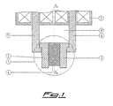
- the novel aspect of the lifter according to the present invention is that of including a dipolar mobile pole 1 made up of two ferromagnetic pole pieces 2, 3 joined through an elastic connection consisting of an elastomer 4. Said mobile pole 1 is inserted between two opposite polarities 5, 6 of an electromagnet 7 so as to be able to slide within a suitable housing 8 formed therebetween, with the two pole pieces 2, 3 respectively adjacent to a North polarity and a South polarity.
- pole pieces 2, 3 and of polarities 5, 6 are conventional and allows to prevent the slipping out of the mobile pole 1, and it provides an air gap T which in time may significantly increase in width due to wear.
- the mobile pole 1 gets in contact with the ferromagnetic load 9 to be lifted and, upon activation of the electromagnet 7, the two pole pieces 2, 3 tend to move away from each other until they adhere through magnetic attraction each one to its own adjacent polarity 5, 6 by dilating elastomer 4 as required, so that they too become a North polarity and a South polarity and substantially cancel the structural air gaps T and the consequent leaks.
- each dipole is put in the condition of being able to effectively lift a single load with a minimum contact loss and no sliding problems, even if pole 1 is partially retracted, since there is a direct magnetic lock on the North and South polarities of the lifter.
- Elastomer 4 is designed to have an elasticity suitable for the lifter power, so as to allow a complete cancellation of the air gaps T during operation while maintaining the capacity of moving near again the pole pieces 2, 3 even after many operating cycles to guarantee a smooth sliding of the mobile pole 1.
- vulcanized rubber with a Shore hardness in the range of 50-60 may be used, to which the pole pieces 2, 3 are secured by gluing or through fastening means (e.g. bolts).
- a further advantage of said mobile poles 1 coming from the presence of elastomer 4 is their capacity of absorbing possible bumps even to a significant extent without damages.
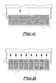
- the longitudinal sectional views of figs.4 and 5 illustrate how the lifter may include a single long mobile pole or a row of independent mobile poles which are however enclosed between only two fixed poles 5, 6. Obviously there is also provided the arrangement, similar to the conventional one, of a series of mobile poles sliding between as many pairs of fixed poles.
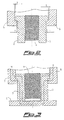
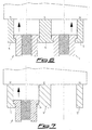
- the frontal sectional views of figs.6 and 7 illustrate how the lifter may include two (rows of) mobile poles 1 side to side which share a fixed "two-faced" central pole 6', or a single pole (or row of poles) 1 combined with a further fixed pole 5" which operates in cooperation with a central fixed pole 6" of greater width.
- the elastic connection between the pole pieces 2 and 3 could be achieved by any other material which in addition to make physically integral the dipole allows for the necessary operating elasticity; such as clothes of various fabrics, sheet of nonmagnetic material, coil springs, etc.
Landscapes
- Physics & Mathematics (AREA)
- Electromagnetism (AREA)
- Engineering & Computer Science (AREA)
- Power Engineering (AREA)
- Mechanical Engineering (AREA)
- Control Of Vehicles With Linear Motors And Vehicles That Are Magnetically Levitated (AREA)
- Electromagnets (AREA)
Claims (7)
- Magnetischer Heber, dadurch gekennzeichnet, dass er mindestens einen dipolaren beweglichen Pol (1) aufweist, der sich aus zwei ferromagnetischen Polstücken (2, 3) zusammensetzt, die durch ein elastisches Verbindungsstück verbunden sind, und zwischen zwei festsitzende entgegengesetzte Polungen (Pole) (5, 6) eingefügt sind, so dass sie imstande sind, innerhalb eines zwischen ihnen gebildeten Gehäuses (8) zu gleiten.
- Magnetischer Heber gemäß Patentanspruch 1, dadurch gekennzeichnet, dass das elastische Verbindungsstück aus einem Elastomer (4) besteht.
- Magnetischer Heber gemäß Patentanspruch 2, dadurch gekennzeichnet, dass das elastische Verbindungsstück aus vulkanisiertem Gummi einer SHORE-Härte im Bereich 50-60 hergestellt ist.
- Magnetischer Heber nach einem oder mehreren der vorangehenden Patentansprüchen, dadurch gekennzeichnet, dass dieser eine Vielzahl unabhängiger beweglicher Pole (1) aufweist, die zwischen nur zwei festen Polen (5, 6) abgeglichen und eingeschlossen sind.
- Magnetischer Heber, nach einem oder mehreren der vorangehenden Patentansprüche, dadurch gekennzeichnet, dass dieser mindestens zwei bewegliche Pole (1) Seite an Seite aufweist, die sich einen zentralen festen Pol (6') zweier Vorderflächen teilen.
- Magnetischer Heber nach einem oder mehrerer der vorangehenden Patentansprüche, dadurch gekennzeichnet, dass dieser mindestens einen weiteren festen Pol (5") enthält, der mit einem der festen Pole (6") zusammenarbeitet und als eine Gleitführung für einen oder mehrere bewegliche Pole (1) wirkt.
- Magnetischer Heber gemäß Patentanspruch 6, dadurch gekennzeichnet, dass der feste Pol (6"), der mit dem genannten festen Pol (5") zusammenarbeitet, eine größere Breite besitzt.
Applications Claiming Priority (1)
| Application Number | Priority Date | Filing Date | Title |
|---|---|---|---|
| PCT/IT2002/000530 WO2004015726A1 (en) | 2002-08-08 | 2002-08-08 | Mobile-pole lifter for moving ferromagnetic loads |
Publications (2)
| Publication Number | Publication Date |
|---|---|
| EP1529295A1 EP1529295A1 (de) | 2005-05-11 |
| EP1529295B1 true EP1529295B1 (de) | 2008-11-26 |
Family
ID=31503926
Family Applications (1)
| Application Number | Title | Priority Date | Filing Date |
|---|---|---|---|
| EP02772803A Expired - Lifetime EP1529295B1 (de) | 2002-08-08 | 2002-08-08 | Hubeinrichtung mit beweglichen polstücken zum bewegen von ferromagnetischen lasten |
Country Status (3)
| Country | Link |
|---|---|
| US (1) | US20060119119A1 (de) |
| EP (1) | EP1529295B1 (de) |
| WO (1) | WO2004015726A1 (de) |
Families Citing this family (2)
| Publication number | Priority date | Publication date | Assignee | Title |
|---|---|---|---|---|
| KR102390600B1 (ko) * | 2014-06-20 | 2022-04-27 | 에스지엠 메그네틱스 에스.피.에이. | 고온 재료들을 위한 전자기 리프터 |
| WO2021224123A1 (de) * | 2020-05-07 | 2021-11-11 | Bayer Aktiengesellschaft | Greifvorrichtung zum transfer eines magnetischen dipolstabs |
Family Cites Families (4)
| Publication number | Priority date | Publication date | Assignee | Title |
|---|---|---|---|---|
| DE1756503C3 (de) * | 1968-05-30 | 1973-07-19 | Koppers Gmbh Heinrich | Vorrichtung zur Anzeige von an Lasthebemagneten haengenden Lasten |
| JPS51108497A (en) * | 1975-03-18 | 1976-09-25 | Kohan Sendan Kikai Kk | Taguhoototo senpakutoorenketsusurusochi |
| DE3212465A1 (de) * | 1982-04-02 | 1983-10-20 | Emag Maschinenfabrik Gmbh, 7335 Salach | Transportvorrichtung, insbesondere ladevorrichtung fuer bearbeitungsmaschinen |
| DE3228178C2 (de) * | 1982-07-28 | 1985-11-28 | Steinert Elektromagnetbau GmbH, 5000 Köln | Lasthebemagnet |
-
2002
- 2002-08-08 EP EP02772803A patent/EP1529295B1/de not_active Expired - Lifetime
- 2002-08-08 WO PCT/IT2002/000530 patent/WO2004015726A1/en not_active Ceased
- 2002-08-08 US US10/524,005 patent/US20060119119A1/en not_active Abandoned
Also Published As
| Publication number | Publication date |
|---|---|
| EP1529295A1 (de) | 2005-05-11 |
| WO2004015726A1 (en) | 2004-02-19 |
| US20060119119A1 (en) | 2006-06-08 |
Similar Documents
| Publication | Publication Date | Title |
|---|---|---|
| JP7317085B2 (ja) | 複数のデバイスを充電するための折り畳み可能剛性ドッキングステーション | |
| US3978441A (en) | Permanent magnet holding system | |
| US4075589A (en) | Magnetic plate comprising permanent magnets and electropermanent magnets | |
| ES2579934T3 (es) | Conjunto de relé electromagnético | |
| EP2502857B1 (de) | Kettensfördersystem | |
| CN113226955B (zh) | 输送机系统中的磁性耦合布置 | |
| CN101398524B (zh) | 透镜驱动装置 | |
| RU97117943A (ru) | Электромеханическое соединительное устройство | |
| RU97118141A (ru) | Электромеханическое соединительное устройство | |
| EP3599756B1 (de) | Gleitschiene und mobiles endgerät | |
| CN103367049A (zh) | 有极电磁继电器 | |
| EP1529295B1 (de) | Hubeinrichtung mit beweglichen polstücken zum bewegen von ferromagnetischen lasten | |
| US20170178779A1 (en) | Electromagnetic actuator | |
| EP1338818A3 (de) | Ringförmige Federvorrichtung | |
| CA2288827A1 (en) | Relay with contact springs | |
| ES2648115T3 (es) | Contactor magnético | |
| US8220610B2 (en) | Overload protection device | |
| US2342797A (en) | Shading coil | |
| CN103489718A (zh) | 一种接触器的双稳态永磁电磁系统 | |
| CN221499804U (zh) | 用于具有载体和设置在载体上的磁体的高架输送机的磁体盖和高架输送机组件 | |
| CN200976539Y (zh) | 磁力驱动及离合装置 | |
| RU97107787A (ru) | Магнитная муфта | |
| WO2007089240A1 (en) | A voice coil actuator having a flux guide at both ends | |
| KR20190114123A (ko) | 영전자석 | |
| NL1044109B1 (en) | Rotary assembly |
Legal Events
| Date | Code | Title | Description |
|---|---|---|---|
| PUAI | Public reference made under article 153(3) epc to a published international application that has entered the european phase |
Free format text: ORIGINAL CODE: 0009012 |
|
| 17P | Request for examination filed |
Effective date: 20050218 |
|
| AK | Designated contracting states |
Kind code of ref document: A1 Designated state(s): AT BE BG CH CY CZ DE DK EE ES FI FR GB GR IE IT LI LU MC NL PT SE SK TR |
|
| AX | Request for extension of the european patent |
Extension state: AL LT LV MK RO SI |
|
| DAX | Request for extension of the european patent (deleted) | ||
| RBV | Designated contracting states (corrected) |
Designated state(s): FR IT |
|
| REG | Reference to a national code |
Ref country code: DE Ref legal event code: 8566 |
|
| GRAP | Despatch of communication of intention to grant a patent |
Free format text: ORIGINAL CODE: EPIDOSNIGR1 |
|
| GRAS | Grant fee paid |
Free format text: ORIGINAL CODE: EPIDOSNIGR3 |
|
| GRAA | (expected) grant |
Free format text: ORIGINAL CODE: 0009210 |
|
| AK | Designated contracting states |
Kind code of ref document: B1 Designated state(s): FR IT |
|
| PLBE | No opposition filed within time limit |
Free format text: ORIGINAL CODE: 0009261 |
|
| STAA | Information on the status of an ep patent application or granted ep patent |
Free format text: STATUS: NO OPPOSITION FILED WITHIN TIME LIMIT |
|
| 26N | No opposition filed |
Effective date: 20090827 |
|
| REG | Reference to a national code |
Ref country code: FR Ref legal event code: ST Effective date: 20110502 |
|
| PG25 | Lapsed in a contracting state [announced via postgrant information from national office to epo] |
Ref country code: FR Free format text: LAPSE BECAUSE OF NON-PAYMENT OF DUE FEES Effective date: 20100831 |
|
| PGFP | Annual fee paid to national office [announced via postgrant information from national office to epo] |
Ref country code: FR Payment date: 20090914 Year of fee payment: 8 |
|
| PGFP | Annual fee paid to national office [announced via postgrant information from national office to epo] |
Ref country code: IT Payment date: 20120716 Year of fee payment: 11 |
|
| PG25 | Lapsed in a contracting state [announced via postgrant information from national office to epo] |
Ref country code: IT Free format text: LAPSE BECAUSE OF NON-PAYMENT OF DUE FEES Effective date: 20130808 |