EP1528802B1 - Display apparatus with shielding - Google Patents
Display apparatus with shielding Download PDFInfo
- Publication number
- EP1528802B1 EP1528802B1 EP20040300544 EP04300544A EP1528802B1 EP 1528802 B1 EP1528802 B1 EP 1528802B1 EP 20040300544 EP20040300544 EP 20040300544 EP 04300544 A EP04300544 A EP 04300544A EP 1528802 B1 EP1528802 B1 EP 1528802B1
- Authority
- EP
- European Patent Office
- Prior art keywords
- shielding
- face plate
- videodisplay
- cam
- base plate
- Prior art date
- Legal status (The legal status is an assumption and is not a legal conclusion. Google has not performed a legal analysis and makes no representation as to the accuracy of the status listed.)
- Expired - Lifetime
Links
Images

Classifications
-
- H—ELECTRICITY
- H04—ELECTRIC COMMUNICATION TECHNIQUE
- H04N—PICTORIAL COMMUNICATION, e.g. TELEVISION
- H04N5/00—Details of television systems
- H04N5/64—Constructional details of receivers, e.g. cabinets or dust covers
-
- H—ELECTRICITY
- H04—ELECTRIC COMMUNICATION TECHNIQUE
- H04N—PICTORIAL COMMUNICATION, e.g. TELEVISION
- H04N5/00—Details of television systems
- H04N5/64—Constructional details of receivers, e.g. cabinets or dust covers
- H04N5/65—Holding-devices for protective discs or for picture masks
-
- H—ELECTRICITY
- H04—ELECTRIC COMMUNICATION TECHNIQUE
- H04N—PICTORIAL COMMUNICATION, e.g. TELEVISION
- H04N5/00—Details of television systems
- H04N5/72—Modifying the appearance of television pictures by optical filters or diffusing screens
Definitions
- the invention is related to a display apparatus comprising a display device mounted in a housing and having a face plate.
- the surface of the face plate of a current display apparatus is usually provided with coatings to reduce reflexions and to harden its surface against scratches or other mechanical disturbances.
- the face plate additionally also includes optical elements to achieve the desired image quality.
- a filter assembly is mounted in various ways in front of the display. Basically, the filter assembly is fixed by the engagement of latches into corresponding openings.
- EP-A 0 385 037 describes an improved filter screen device for cathode ray tubes (CRT).
- the device is provided with hangers fitted in the frame.
- Each hanger includes a hanger bar which extends beyond frame member and is pivotally connected through pin to a CRT mounting bar.
- US-A 5,543,863 discloses an eye protecting mask for a computer and video display.
- the eye protecting mask is pivotally fastened in front of the display screen.
- An adjustment device is disposed at the top side of the television screen or the computer video display for holding a frame of the eye protecting mask.
- the adjustment device comprises a base and a pivoting member.
- the frame can be pivoted in front of the screen or upwards outside of the direct viewing direction.
- EP-A 0 331 349 a protective screen for a visual display device is shown.
- the protective screen is articulated around a pivotal connection between an upper plate fixed to the housing of the display device and the protective screen.
- the invention suggests a display apparatus as defined in claim 1 to respond to these needs.
- the inventive videodisplay apparatus comprises a display device mounted in a housing and having a face plate.
- a shielding is mounted in front of the face plate in a detachable manner allowing an easy replacement or exchange of the shielding.
- the shielding is transparent. It is convenient if means for detaching the shielding are provided.
- the means for detaching comprise a rotatable cam.
- the means for detaching may comprise a base plate bearing the rotatable cam.
- a lever may be drivingly connected to the rotatable cam for rotating the cam.
- the lever forms an even surface relative to a front side of the shielding or relative to a front side of the face plate.
- the means for detaching comprise a base plate bearing the rotatable cam.
- the base plate may comprise a locking element locking the cam in the base plate. It is advantageous if the base plate is attached to the shielding.
- the base plate is provided with a first indexing element and the face plate with a complementary second indexing element to locate the shielding on the face plate.
- An additional advantage of all embodiments of the present invention is that children cannot easily detach the shielding and thus protecting the children against any kind of injuries that may be caused if the shielding is no longer fixed on the face plate. E.g. a detached shielding could drop on a foot of a child and hurt it.
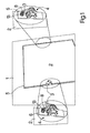
- Fig. 1 shows a schematic illustration of the front view of an exemplary embodiment of the inventive video display apparatus.
- the invention will be described in the following in connection with a television receiver.
- the invention is not limited to television receivers but can be incorporated in any kind of display apparatus like for example computer monitors.
- Fig. 1 exhibits the front view of a face plate or front panel 1 of a television cabinet the reminder of which is not shown in the drawing.
- the cabinet houses the receiver and a display device like a cathode raytube (CRT), an LCD panel (liquid crystal panel), a plasma panel or the screen of a rear projector.
- the face plate 1 is provided with a cut-out window 5 or recess in its center portion accommodating a protective screen shield or shielding 2 in front of a face plate of the display device.
- the dimensions of the window 5 and the shielding are adapted to provide a flat surface across the face plate 1 and the shielding 2 as shown in Fig. 1 .
- the flat surface makes it very difficult to remove the shielding from the recess in the face plate.
- rotatable levers 3 are provided on the lateral sides of the shielding 2.
- the levers 3 are aligned with the surface defined by the shielding 2 and face plate 1 as it is shown on the right side of Fig. 1 .
- the visibility of the levers is therefore limited which is very favourable for some designs.
- the levers 3 are rotatable around a horizontal axis by pushing one lever arm with a finger tip to make the opposite lever arm raise above the surface of the face plate as it is illustrated in the enlarged portion on the left side of Fig. 1 .
- Fig. 1 show the respective sections of the shielding 2 from the rear.
- Each lever arm 3 forms part of an extractor mechanism 4 and is effective to operate the extractor mechanism which is shown in greater detail from the rear side of the face plate and on a different scale on the left and on the right side of the face plate 1 in Fig. 1 .
- the structure and functionality of the extractor mechanism 4 will be described in further detail below.
- Fig. 2 illustrates the shielding 2 in the mounted position from the rear side without showing the face plate 1.
- the extractor mechanism 4 includes a base plate 6 which is securely connected with a rear side of shield 2 e.g. by a moulding connection or by glueing.
- the lever 3 is arranged on a rotatable shaft 7 carrying a cam 8.
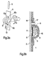
- Fig. 3a displays an exploded perspective view of the extractor mechanism 4.
- the lever 3 is securely fixed on the shaft 7 carrying the cam 8 having a height H.
- the shaft 7 is inserted under two bow 9 being part of the base plate 6.
- a locking plate 11 is inserted between the bows 9 and between the shaft 7 and the base plate 6 to form a bearing in which a shaft 7 is rotatably mounted.
- the locking plate 11 is guided by a ridge having two lateral sides 12a, 12b and a front side 12c.
- the front side 12c is an effective abutment for the insertion of the locking plate 11.
- An index protrusion 13 forms part of the base plate 6.
- Fig. 3b shows a sectional side view of the assembled extractor mechanism 4 mounted on the shielding 2 which itself is in the mounted position on the face plate 1.
- a recess 14 is provided to accommodate the base plate 6 of the extractor mechanism 4.
- An arcuate portion 16 of the face plate 1 covers the cam 8 and the bow 9 of the base plate 6 in close vicinity. Adjacent to the arcuate portion 16 the face plate is provided with an index aperture 17. The cooperation of the index protrusions 13 with the associated index apertures 17 secures the proper positioning of the shielding 2 on the face plate 1.
- a user turns the lever 3 and thus the cam 8 clockwise in Fig. 3b .
- the periphery of the cam 8 contacts the arcuate portion 16 and generates a force directed to the left side in Fig. 3b .
- the force urges the shielding 2 out of the recess 14 and out of the window 5 in face plate 1. Now the user can easily grasp the rim of the shielding 2 to completely remove it from the face plate 1.
- the levers are arranged parallel to the surface of the shielding 2. Then the index protrusions 13 are aligned with the index apertures 17 and the shielding 2 is pushed into the window 5. The proper positioning of the shielding 2 is facilitated by the conical shape of the end portion of the index protrusion 13 tolerating small deviations from the exact position at the beginning of the insertion of the shielding 2.
- the present invention is not limited to embodiments, in which the face plate is located on the front side of the apparatus and the shielding 2 is not necessarily a protective screen shield.
Landscapes
- Engineering & Computer Science (AREA)
- Multimedia (AREA)
- Signal Processing (AREA)
- Devices For Indicating Variable Information By Combining Individual Elements (AREA)
Description
- The invention is related to a display apparatus comprising a display device mounted in a housing and having a face plate. The surface of the face plate of a current display apparatus is usually provided with coatings to reduce reflexions and to harden its surface against scratches or other mechanical disturbances. For projection displays the face plate additionally also includes optical elements to achieve the desired image quality.
- It is known in the art e.g. from
JP 2000-182519 - In
US 6,268,960 a display device is disclosed. A filter assembly is mounted in various ways in front of the display. Basically, the filter assembly is fixed by the engagement of latches into corresponding openings. -
EP-A 0 385 037 describes an improved filter screen device for cathode ray tubes (CRT).
The device is provided with hangers fitted in the frame. Each hanger includes a hanger bar which extends beyond frame member and is pivotally connected through pin to a CRT mounting bar. -
US-A 5,543,863 discloses an eye protecting mask for a computer and video display. The eye protecting mask is pivotally fastened in front of the display screen. An adjustment device is disposed at the top side of the television screen or the computer video display for holding a frame of the eye protecting mask. The adjustment device comprises a base and a pivoting member. The frame can be pivoted in front of the screen or upwards outside of the direct viewing direction. - In
EP-A 0 331 349 a protective screen for a visual display device is shown. The protective screen is articulated around a pivotal connection between an upper plate fixed to the housing of the display device and the protective screen. - Still, there remains a desire to provide a display apparatus equipped with a shielding which is easily mountable and unmountable. In addition, it is preferable if the aesthetic impression of the display apparatus is not impaired.
- The invention suggests a display apparatus as defined in
claim 1 to respond to these needs. - The inventive videodisplay apparatus comprises a display device mounted in a housing and having a face plate. A shielding is mounted in front of the face plate in a detachable manner allowing an easy replacement or exchange of the shielding. In an advantageous embodiment of the invention the shielding is transparent. It is convenient if means for detaching the shielding are provided. In a particular embodiment of the invention the means for detaching comprise a rotatable cam. In addition, the means for detaching may comprise a base plate bearing the rotatable cam. A lever may be drivingly connected to the rotatable cam for rotating the cam. With regard to the appearance of the apparatus it is advantageous to accommodate the lever in a recess adjacent to the shielding. Preferably, the lever forms an even surface relative to a front side of the shielding or relative to a front side of the face plate.
- In another embodiment of the invention the means for detaching comprise a base plate bearing the rotatable cam. The base plate may comprise a locking element locking the cam in the base plate. It is advantageous if the base plate is attached to the shielding.
- In a preferred embodiment the base plate is provided with a first indexing element and the face plate with a complementary second indexing element to locate the shielding on the face plate.
- An additional advantage of all embodiments of the present invention is that children cannot easily detach the shielding and thus protecting the children against any kind of injuries that may be caused if the shielding is no longer fixed on the face plate. E.g. a detached shielding could drop on a foot of a child and hurt it.
- In the drawing an exemplary embodiment of the invention is illustrated. It shows:
-
Fig. 1 a front view of the inventive display apparatus including a protective screen; -
Fig. 2 a rear view of the protective screen ofFig. 1 including exstractor mechanisms, and -
Fig. 3a, and 3b details of the exstractor mechanism shown inFig. 2 . -
Fig. 1 shows a schematic illustration of the front view of an exemplary embodiment of the inventive video display apparatus. For the sake of simplicity the invention will be described in the following in connection with a television receiver. However, the invention is not limited to television receivers but can be incorporated in any kind of display apparatus like for example computer monitors. -
Fig. 1 exhibits the front view of a face plate orfront panel 1 of a television cabinet the reminder of which is not shown in the drawing. The cabinet houses the receiver and a display device like a cathode raytube (CRT), an LCD panel (liquid crystal panel), a plasma panel or the screen of a rear projector. Theface plate 1 is provided with a cut-outwindow 5 or recess in its center portion accommodating a protective screen shield or shielding 2 in front of a face plate of the display device. The dimensions of thewindow 5 and the shielding are adapted to provide a flat surface across theface plate 1 and theshielding 2 as shown inFig. 1 . The flat surface makes it very difficult to remove the shielding from the recess in the face plate. Therefore,rotatable levers 3 are provided on the lateral sides of theshielding 2. When theshielding 2 is mounted, thelevers 3 are aligned with the surface defined by theshielding 2 andface plate 1 as it is shown on the right side ofFig. 1 . The visibility of the levers is therefore limited which is very favourable for some designs. Thelevers 3 are rotatable around a horizontal axis by pushing one lever arm with a finger tip to make the opposite lever arm raise above the surface of the face plate as it is illustrated in the enlarged portion on the left side ofFig. 1 . - It is noted that the enlarged partial views in
Fig. 1 show the respective sections of theshielding 2 from the rear. - Each
lever arm 3 forms part of anextractor mechanism 4 and is effective to operate the extractor mechanism which is shown in greater detail from the rear side of the face plate and on a different scale on the left and on the right side of theface plate 1 inFig. 1 . The structure and functionality of theextractor mechanism 4 will be described in further detail below. -
Fig. 2 illustrates theshielding 2 in the mounted position from the rear side without showing theface plate 1. In the mounted position thelevers 3 are aligned with a surface of theshield 2 as it has been described with reference toFig. 1 . Theextractor mechanism 4 includes abase plate 6 which is securely connected with a rear side ofshield 2 e.g. by a moulding connection or by glueing. Thelever 3 is arranged on a rotatable shaft 7 carrying acam 8. -
Fig. 3a displays an exploded perspective view of theextractor mechanism 4. Thelever 3 is securely fixed on the shaft 7 carrying thecam 8 having a height H. For the assembly of theextractor mechanism 4 the shaft 7 is inserted under twobow 9 being part of thebase plate 6. Subsequently, a lockingplate 11 is inserted between thebows 9 and between the shaft 7 and thebase plate 6 to form a bearing in which a shaft 7 is rotatably mounted. During the insertion thelocking plate 11 is guided by a ridge having twolateral sides front side 12c. Thefront side 12c is an effective abutment for the insertion of the lockingplate 11. Anindex protrusion 13 forms part of thebase plate 6. -
Fig. 3b shows a sectional side view of the assembledextractor mechanism 4 mounted on the shielding 2 which itself is in the mounted position on theface plate 1. In the face plate 1 arecess 14 is provided to accommodate thebase plate 6 of theextractor mechanism 4. Anarcuate portion 16 of theface plate 1 covers thecam 8 and thebow 9 of thebase plate 6 in close vicinity. Adjacent to thearcuate portion 16 the face plate is provided with anindex aperture 17. The cooperation of theindex protrusions 13 with the associatedindex apertures 17 secures the proper positioning of the shielding 2 on theface plate 1. - For the extraction of the shielding 2 a user turns the
lever 3 and thus thecam 8 clockwise inFig. 3b . In consequence the periphery of thecam 8 contacts thearcuate portion 16 and generates a force directed to the left side inFig. 3b . The force urges the shielding 2 out of therecess 14 and out of thewindow 5 inface plate 1. Now the user can easily grasp the rim of the shielding 2 to completely remove it from theface plate 1. - For the mounting of a
new shielding 2 the levers are arranged parallel to the surface of theshielding 2. Then the index protrusions 13 are aligned with theindex apertures 17 and the shielding 2 is pushed into thewindow 5. The proper positioning of the shielding 2 is facilitated by the conical shape of the end portion of theindex protrusion 13 tolerating small deviations from the exact position at the beginning of the insertion of theshielding 2. - It is noted that the present invention is not limited to embodiments, in which the face plate is located on the front side of the apparatus and the shielding 2 is not necessarily a protective screen shield.
Claims (10)
- Videodisplay apparatus comprising a display device mounted in a housing and having a face plate (1) and a detachable shielding (2) mounted in front of the face plate (1), wherein means (4) for detaching the shielding (2) are provided, characterized in that that the means (4) for detaching comprise a rotatable cam (8), and
that the cam (8) is in mechanical contact with the face plate (1) such that rotating the cam creates a force separating the shielding (2) from the face plate (1). - Videodisplay apparatus according to claim 1, characterized in that the shielding (2) is transparent.
- Videodisplay apparatus according to claim 1, characterized in that a lever (3) is drivingly connected to the rotatable cam (8) for rotating the cam.
- Videodisplay apparatus according to claim 3, characterized in that the lever (3) is accommodated in a recess adjacent to the shielding (2).
- Videodisplay apparatus according to claim 4, characterized in that the lever (3) forms an even surface relative to a front side of the shielding (2).
- Videodisplay apparatus according to claim 4, characterized in that the lever (3) forms an even surface relative to a front side of the face plate (1).
- videodisplay apparatus according to claim 1, characterized in that the means (4) for detaching comprise a base plate (6) bearing the rotatable cam (8).
- Videodisplay apparatus according to claim 7, characterized in that the base plate (6) comprises a locking element (11) locking the cam (8) in the base plate (6).
- Videodisplay apparatus according to claim 7, characterized in that the base plate (6) is attached on the shielding (2).
- Video display apparatus according to claim 7, characterized in that the base plate (6) is provided with a first indexing element (13) and the face plate (1) with a complementary second indexing element (17) to locate the shielding on the face plate (1).
Priority Applications (1)
| Application Number | Priority Date | Filing Date | Title |
|---|---|---|---|
| EP20040300544 EP1528802B1 (en) | 2003-10-29 | 2004-08-17 | Display apparatus with shielding |
Applications Claiming Priority (3)
| Application Number | Priority Date | Filing Date | Title |
|---|---|---|---|
| EP33001827 | 2003-10-29 | ||
| EP03300182A EP1528801A1 (en) | 2003-10-29 | 2003-10-29 | Display apparatus with shielding |
| EP20040300544 EP1528802B1 (en) | 2003-10-29 | 2004-08-17 | Display apparatus with shielding |
Publications (2)
| Publication Number | Publication Date |
|---|---|
| EP1528802A1 EP1528802A1 (en) | 2005-05-04 |
| EP1528802B1 true EP1528802B1 (en) | 2011-02-23 |
Family
ID=34424783
Family Applications (1)
| Application Number | Title | Priority Date | Filing Date |
|---|---|---|---|
| EP20040300544 Expired - Lifetime EP1528802B1 (en) | 2003-10-29 | 2004-08-17 | Display apparatus with shielding |
Country Status (1)
| Country | Link |
|---|---|
| EP (1) | EP1528802B1 (en) |
Families Citing this family (1)
| Publication number | Priority date | Publication date | Assignee | Title |
|---|---|---|---|---|
| IL116255A (en) * | 1995-01-05 | 2004-02-19 | Du Pont | High-solids coating composition |
Family Cites Families (4)
| Publication number | Priority date | Publication date | Assignee | Title |
|---|---|---|---|---|
| IT214515Z2 (en) * | 1988-03-03 | 1990-05-09 | Baltea | PROTECTION SCREEN FOR DISPLAY |
| US4905089A (en) * | 1989-01-03 | 1990-02-27 | Rcs Technology Corporation | Filter screen for cathode ray tubes |
| US5543863A (en) * | 1995-01-20 | 1996-08-06 | Three Soma Technology Co., Ltd. | Eye protecting mask of computer video display |
| JPH11242443A (en) * | 1997-10-15 | 1999-09-07 | Kyowa Electric & Chem Co Ltd | Image enlarging observation system and filter assembly for the system |
-
2004
- 2004-08-17 EP EP20040300544 patent/EP1528802B1/en not_active Expired - Lifetime
Also Published As
| Publication number | Publication date |
|---|---|
| EP1528802A1 (en) | 2005-05-04 |
Similar Documents
| Publication | Publication Date | Title |
|---|---|---|
| EP0722248B1 (en) | Optical filter for visual display terminals | |
| EP1528802B1 (en) | Display apparatus with shielding | |
| US11892643B2 (en) | Augmented reality glasses | |
| EP1528801A1 (en) | Display apparatus with shielding | |
| EP1783583B1 (en) | Cabinet for large display panels and method of assembling the cabinet | |
| CN208110961U (en) | A kind of LED display with shell gap light-shielding structure | |
| JPH0996779A (en) | Liquid crystal shutter spectacles for wireless stereoscopic vision | |
| JPH06315124A (en) | Spectacles type video display device | |
| US20060226307A1 (en) | Display apparatus | |
| US20030048047A1 (en) | Image display device and frame for such a device | |
| JP3395242B2 (en) | Glasses-type image display device | |
| KR20190061182A (en) | Head up display device for vehicle | |
| CN219439696U (en) | Combined goggles capable of quickly replacing lenses | |
| CN218870648U (en) | Fixing structure of welding mask | |
| JPH10244066A (en) | Folding type display device in game machine | |
| JPH06315121A (en) | Eyeglass type image display device | |
| KR960000471Y1 (en) | Fixture for eye protection for computer monitor | |
| JPH04341078A (en) | Glasses for television | |
| JP2515641B2 (en) | TV camera | |
| JPS6010115Y2 (en) | Channel selection device | |
| KR200302252Y1 (en) | Coupling System For Securing An Eyeglass Frame To A Cap Visor | |
| HK1007933B (en) | Optical filter for visual display terminals | |
| KR200377669Y1 (en) | Mobile communication terminal having camera deco | |
| JP2941679B2 (en) | Variable display device for pachinko machines | |
| US20120140390A1 (en) | Portable electronic apparatus |
Legal Events
| Date | Code | Title | Description |
|---|---|---|---|
| PUAI | Public reference made under article 153(3) epc to a published international application that has entered the european phase |
Free format text: ORIGINAL CODE: 0009012 |
|
| AK | Designated contracting states |
Kind code of ref document: A1 Designated state(s): AT BE BG CH CY CZ DE DK EE ES FI FR GB GR HU IE IT LI LU MC NL PL PT RO SE SI SK TR |
|
| AX | Request for extension of the european patent |
Extension state: AL HR LT LV MK |
|
| RAP1 | Party data changed (applicant data changed or rights of an application transferred) |
Owner name: THOMSON LICENSING |
|
| 17P | Request for examination filed |
Effective date: 20051020 |
|
| AKX | Designation fees paid |
Designated state(s): DE ES FR GB IT TR |
|
| 17Q | First examination report despatched |
Effective date: 20070515 |
|
| RAP1 | Party data changed (applicant data changed or rights of an application transferred) |
Owner name: THOMSON LICENSING |
|
| GRAP | Despatch of communication of intention to grant a patent |
Free format text: ORIGINAL CODE: EPIDOSNIGR1 |
|
| GRAS | Grant fee paid |
Free format text: ORIGINAL CODE: EPIDOSNIGR3 |
|
| GRAA | (expected) grant |
Free format text: ORIGINAL CODE: 0009210 |
|
| AK | Designated contracting states |
Kind code of ref document: B1 Designated state(s): DE ES FR GB IT TR |
|
| REG | Reference to a national code |
Ref country code: GB Ref legal event code: FG4D |
|
| REG | Reference to a national code |
Ref country code: DE Ref legal event code: R084 Ref document number: 602004031495 Country of ref document: DE |
|
| REG | Reference to a national code |
Ref country code: GB Ref legal event code: 746 Effective date: 20110315 |
|
| REF | Corresponds to: |
Ref document number: 602004031495 Country of ref document: DE Date of ref document: 20110407 Kind code of ref document: P |
|
| REG | Reference to a national code |
Ref country code: DE Ref legal event code: R096 Ref document number: 602004031495 Country of ref document: DE Effective date: 20110407 |
|
| PG25 | Lapsed in a contracting state [announced via postgrant information from national office to epo] |
Ref country code: ES Free format text: LAPSE BECAUSE OF FAILURE TO SUBMIT A TRANSLATION OF THE DESCRIPTION OR TO PAY THE FEE WITHIN THE PRESCRIBED TIME-LIMIT Effective date: 20110603 |
|
| PLBE | No opposition filed within time limit |
Free format text: ORIGINAL CODE: 0009261 |
|
| STAA | Information on the status of an ep patent application or granted ep patent |
Free format text: STATUS: NO OPPOSITION FILED WITHIN TIME LIMIT |
|
| 26N | No opposition filed |
Effective date: 20111124 |
|
| REG | Reference to a national code |
Ref country code: DE Ref legal event code: R097 Ref document number: 602004031495 Country of ref document: DE Effective date: 20111124 |
|
| PG25 | Lapsed in a contracting state [announced via postgrant information from national office to epo] |
Ref country code: IT Free format text: LAPSE BECAUSE OF FAILURE TO SUBMIT A TRANSLATION OF THE DESCRIPTION OR TO PAY THE FEE WITHIN THE PRESCRIBED TIME-LIMIT Effective date: 20110223 |
|
| PG25 | Lapsed in a contracting state [announced via postgrant information from national office to epo] |
Ref country code: TR Free format text: LAPSE BECAUSE OF FAILURE TO SUBMIT A TRANSLATION OF THE DESCRIPTION OR TO PAY THE FEE WITHIN THE PRESCRIBED TIME-LIMIT Effective date: 20110223 |
|
| REG | Reference to a national code |
Ref country code: FR Ref legal event code: PLFP Year of fee payment: 13 |
|
| REG | Reference to a national code |
Ref country code: DE Ref legal event code: R082 Ref document number: 602004031495 Country of ref document: DE Representative=s name: DEHNS, DE Ref country code: DE Ref legal event code: R082 Ref document number: 602004031495 Country of ref document: DE Representative=s name: DEHNS PATENT AND TRADEMARK ATTORNEYS, DE Ref country code: DE Ref legal event code: R082 Ref document number: 602004031495 Country of ref document: DE Representative=s name: HOFSTETTER, SCHURACK & PARTNER PATENT- UND REC, DE |
|
| REG | Reference to a national code |
Ref country code: FR Ref legal event code: PLFP Year of fee payment: 14 |
|
| REG | Reference to a national code |
Ref country code: FR Ref legal event code: PLFP Year of fee payment: 15 |
|
| REG | Reference to a national code |
Ref country code: FR Ref legal event code: TP Owner name: THOMSON LICENSING DTV, FR Effective date: 20180830 |
|
| REG | Reference to a national code |
Ref country code: GB Ref legal event code: 732E Free format text: REGISTERED BETWEEN 20180927 AND 20181005 |
|
| REG | Reference to a national code |
Ref country code: DE Ref legal event code: R082 Ref document number: 602004031495 Country of ref document: DE Representative=s name: DEHNS, DE Ref country code: DE Ref legal event code: R081 Ref document number: 602004031495 Country of ref document: DE Owner name: INTERDIGITAL MADISON PATENT HOLDINGS, FR Free format text: FORMER OWNER: THOMSON LICENSING, ISSY-LES-MOULINEAUX, FR Ref country code: DE Ref legal event code: R082 Ref document number: 602004031495 Country of ref document: DE Representative=s name: DEHNS PATENT AND TRADEMARK ATTORNEYS, DE |
|
| P01 | Opt-out of the competence of the unified patent court (upc) registered |
Effective date: 20230514 |
|
| PGFP | Annual fee paid to national office [announced via postgrant information from national office to epo] |
Ref country code: GB Payment date: 20230822 Year of fee payment: 20 |
|
| PGFP | Annual fee paid to national office [announced via postgrant information from national office to epo] |
Ref country code: FR Payment date: 20230824 Year of fee payment: 20 Ref country code: DE Payment date: 20230828 Year of fee payment: 20 |
|
| REG | Reference to a national code |
Ref country code: DE Ref legal event code: R071 Ref document number: 602004031495 Country of ref document: DE |
|
| REG | Reference to a national code |
Ref country code: GB Ref legal event code: PE20 Expiry date: 20240816 |
|
| PG25 | Lapsed in a contracting state [announced via postgrant information from national office to epo] |
Ref country code: GB Free format text: LAPSE BECAUSE OF EXPIRATION OF PROTECTION Effective date: 20240816 |
|
| PG25 | Lapsed in a contracting state [announced via postgrant information from national office to epo] |
Ref country code: GB Free format text: LAPSE BECAUSE OF EXPIRATION OF PROTECTION Effective date: 20240816 |