EP1528801A1 - Display apparatus with shielding - Google Patents
Display apparatus with shielding Download PDFInfo
- Publication number
- EP1528801A1 EP1528801A1 EP03300182A EP03300182A EP1528801A1 EP 1528801 A1 EP1528801 A1 EP 1528801A1 EP 03300182 A EP03300182 A EP 03300182A EP 03300182 A EP03300182 A EP 03300182A EP 1528801 A1 EP1528801 A1 EP 1528801A1
- Authority
- EP
- European Patent Office
- Prior art keywords
- shielding
- face plate
- videodisplay
- base plate
- lever
- Prior art date
- Legal status (The legal status is an assumption and is not a legal conclusion. Google has not performed a legal analysis and makes no representation as to the accuracy of the status listed.)
- Withdrawn
Links
Images

Classifications
-
- H—ELECTRICITY
- H01—ELECTRIC ELEMENTS
- H01J—ELECTRIC DISCHARGE TUBES OR DISCHARGE LAMPS
- H01J29/00—Details of cathode-ray tubes or of electron-beam tubes of the types covered by group H01J31/00
- H01J29/02—Electrodes; Screens; Mounting, supporting, spacing or insulating thereof
-
- H—ELECTRICITY
- H04—ELECTRIC COMMUNICATION TECHNIQUE
- H04N—PICTORIAL COMMUNICATION, e.g. TELEVISION
- H04N5/00—Details of television systems
- H04N5/64—Constructional details of receivers, e.g. cabinets or dust covers
- H04N5/65—Holding-devices for protective discs or for picture masks
-
- G—PHYSICS
- G06—COMPUTING OR CALCULATING; COUNTING
- G06F—ELECTRIC DIGITAL DATA PROCESSING
- G06F1/00—Details not covered by groups G06F3/00 - G06F13/00 and G06F21/00
- G06F1/16—Constructional details or arrangements
- G06F1/1601—Constructional details related to the housing of computer displays, e.g. of CRT monitors, of flat displays
- G06F1/1607—Arrangements to support accessories mechanically attached to the display housing
-
- H—ELECTRICITY
- H01—ELECTRIC ELEMENTS
- H01J—ELECTRIC DISCHARGE TUBES OR DISCHARGE LAMPS
- H01J29/00—Details of cathode-ray tubes or of electron-beam tubes of the types covered by group H01J31/00
- H01J29/86—Vessels; Containers; Vacuum locks
- H01J29/867—Means associated with the outside of the vessel for shielding, e.g. magnetic shields
- H01J29/868—Screens covering the input or output face of the vessel, e.g. transparent anti-static coatings, X-ray absorbing layers
-
- H—ELECTRICITY
- H04—ELECTRIC COMMUNICATION TECHNIQUE
- H04N—PICTORIAL COMMUNICATION, e.g. TELEVISION
- H04N5/00—Details of television systems
- H04N5/72—Modifying the appearance of television pictures by optical filters or diffusing screens
Definitions
- the invention is related to a display apparatus comprising a display device mounted in a housing and having a face plate.
- the surface of the face plate of a current display apparatus is usually provided with coatings to reduce reflexions and to harden its surface against scratches or other mechanical disturbances.
- the face plate additionally also includes optical elements to achieve the desired image quality.
- the invention suggests a display apparatus to respond to these needs.
- the inventive videodisplay apparatus comprises a display device mounted in a housing and having a face plate.
- a shielding is mounted in front of the face plate in a detachable manner allowing an easy replacement or exchange of the shielding.
- the shielding is transparent. It is convenient if means for detaching the shielding are provided.
- the means for detaching comprise a rotatable cam.
- the means for detaching may comprise a base plate bearing the rotatable cam.
- a lever may be drivingly connected to the rotatable cam for rotating the cam.
- the lever forms an even surface relative to a front side of the shielding or relative to a front side of the face plate.
- the means for detaching comprise a base plate bearing the rotatable cam.
- the base plate may comprise a locking element locking the cam in the base plate. It is advantageous if the base plate is attached to the shielding.
- the base plate is provided with a first indexing element and the face plate with a complementary second indexing element to locate the shielding on the face plate.
- An additional advantage of all embodiments of the present invention is that children cannot easily detach the shielding and thus protecting the children against any kind of injuries that may be caused if the shielding is no longer fixed on the face plate. E.g. a detached shielding could drop on a foot of a child and hurt it.
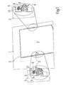
- Fig. 1 shows a schematic illustration of the front view of an exemplary embodiment of the inventive video display apparatus.
- the invention will be described in the following in connection with a television receiver.
- the invention is not limited to television receivers but can be incorporated in any kind of display apparatus like for example computer monitors.
- Fig. 1 exhibits the front view of a face plate or front panel 1 of a television cabinet the reminder of which is not shown in the drawing.
- the cabinet houses the receiver and a display device like a cathode raytube (CRT), an LCD panel (liquid crystal panel), a plasma panel or the screen of a rear projector.
- the face plate 1 is provided with a cut-out window 5 or recess in its center portion accommodating a protective screen shield or shielding 2 in front of a face plate of the display device.
- the dimensions of the window 5 and the shielding are adapted to provide a flat surface across the face plate 1 and the shielding 2 as shown in Fig. 1. The flat surface makes it very difficult to remove the shielding from the recess in the face plate.
- rotatable levers 3 are provided on the lateral sides of the shielding 2.
- the levers 3 are aligned with the surface defined by the shielding 2 and face plate 1 as it is shown on the right side of Fig. 1.
- the visibility of the levers is therefore limited which is very favourable for some designs.
- the levers 3 are rotatable around a horizontal axis by pushing one lever arm with a finger tip to make the opposite lever arm raise above the surface of the face plate as it is illustrated in the enlarged portion on the left side of Fig. 1.
- Fig. 1 show the respective sections of the shielding 2 from the rear.
- Each lever arm 3 forms part of an extractor mechanism 4 and is effective to operate the extractor mechanism which is shown in greater detail from the rear side of the face plate and on a different scale on the left and on the right side of the face plate 1 in Fig. 1.
- the structure and functionality of the extractor mechanism 4 will be described in further detail below.
- Fig. 2 illustrates the shielding 2 in the mounted position from the rear side without showing the face plate 1.
- the extractor mechanism 4 includes a base plate 6 which is securely connected with a rear side of shield 2 e.g. by a moulding connection or by glueing.
- the lever 3 is arranged on a rotatable shaft 7 carrying a cam 8.
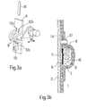
- Fig. 3a displays an exploded perspective view of the extractor mechanism 4.
- the lever 3 is securely fixed on the shaft 7 carrying the cam 8 having a height H.
- the shaft 7 is inserted under two bow 9 being part of the base plate 6.
- a locking plate 11 is inserted between the bows 9 and between the shaft 7 and the base plate 6 to form a bearing in which a shaft 7 is rotatably mounted.
- the locking plate 11 is guided by a ridge having two lateral sides 12a, 12b and a front side 12c.
- the front side 12c is an effective abutment for the insertion of the locking plate 11.
- An index protrusion 13 forms part of the base plate 6.
- Fig. 3b shows a sectional side view of the assembled extractor mechanism 4 mounted on the shielding 2 which itself is in the mounted position on the face plate 1.
- a recess 14 is provided to accommodate the base plate 6 of the extractor mechanism 4.
- An arcuate portion 16 of the face plate 1 covers the cam 8 and the bow 9 of the base plate 6 in close vicinity. Adjacent to the arcuate portion 16 the face plate is provided with an index aperture 17. The cooperation of the index protrusions 13 with the associated index apertures 17 secures the proper positioning of the shielding 2 on the face plate 1.
- a user turns the lever 3 and thus the cam 8 clockwise in Fig. 3b.
- the periphery of the cam 8 contacts the arcuate portion 16 and generates a force directed to the left side in Fig. 3b.
- the force urges the shielding 2 out of the recess 14 and out of the window 5 in face plate 1. Now the user can easily grasp the rim of the shielding 2 to completely remove it from the face plate 1.
- the levers are arranged parallel to the surface of the shielding 2. Then the index protrusions 13 are aligned with the index apertures 17 and the shielding 2 is pushed into the window 5. The proper positioning of the shielding 2 is facilitated by the conical shape of the end portion of the index protrusion 13 tolerating small deviations from the exact position at the beginning of the insertion of the shielding 2.
- the present invention is not limited to embodiments, in which the face plate is located on the front side of the apparatus and the shielding 2 is not necessarily a protective screen shield.
Landscapes
- Engineering & Computer Science (AREA)
- General Engineering & Computer Science (AREA)
- Theoretical Computer Science (AREA)
- Multimedia (AREA)
- Signal Processing (AREA)
- Computer Hardware Design (AREA)
- Human Computer Interaction (AREA)
- Physics & Mathematics (AREA)
- General Physics & Mathematics (AREA)
- Devices For Indicating Variable Information By Combining Individual Elements (AREA)
Abstract
A video display apparatus is provided. The apparatus comprises a display device mounted in a housing and having a face plate (1). A detachable shielding (2) is mounted in front of the face plate (1). In one embodiment means (4) for detaching the shielding (2) are provided.
Description
- The invention is related to a display apparatus comprising a display device mounted in a housing and having a face plate. The surface of the face plate of a current display apparatus is usually provided with coatings to reduce reflexions and to harden its surface against scratches or other mechanical disturbances. For projection displays the face plate additionally also includes optical elements to achieve the desired image quality.
- It is known in the art e.g. from JP 2000-182519 to provide a display with a protective and/or decorative screen shield to protect the screen against scratches, contamination and any other environmental influences being detrimental to the picture quality. The screen shield can also be tinted to improve the contrast of the picture especially in the presence of bright daylight. In order to maintain a superior surface quality or to adapt the tint of the protective screen it is desirable to arrange the protective shield on the display in a detachable manner. This enables the user to replace the currently used protective screen by a new one or by one having a different tint.
- In consequence, it is desirable to provide a display apparatus equipped with a shielding which is easily mountable and unmountable. In addition, it is preferable if the aesthetic impression of the display apparatus is not impaired.
- The invention suggests a display apparatus to respond to these needs.
- The inventive videodisplay apparatus comprises a display device mounted in a housing and having a face plate. A shielding is mounted in front of the face plate in a detachable manner allowing an easy replacement or exchange of the shielding. In an advantageous embodiment of the invention the shielding is transparent. It is convenient if means for detaching the shielding are provided. In a particular embodiment of the invention the means for detaching comprise a rotatable cam. In addition, the means for detaching may comprise a base plate bearing the rotatable cam. A lever may be drivingly connected to the rotatable cam for rotating the cam. With regard to the appearance of the apparatus it is advantageous to accommodate the lever in a recess adjacent to the shielding. Preferably, the lever forms an even surface relative to a front side of the shielding or relative to a front side of the face plate.
- In another embodiment of the invention the means for detaching comprise a base plate bearing the rotatable cam. The base plate may comprise a locking element locking the cam in the base plate. It is advantageous if the base plate is attached to the shielding.
- In a preferred embodiment the base plate is provided with a first indexing element and the face plate with a complementary second indexing element to locate the shielding on the face plate.
- An additional advantage of all embodiments of the present invention is that children cannot easily detach the shielding and thus protecting the children against any kind of injuries that may be caused if the shielding is no longer fixed on the face plate. E.g. a detached shielding could drop on a foot of a child and hurt it.
- In the drawing an exemplary embodiment of the invention is illustrated. It shows:
- Fig. 1 a front view of the inventive display apparatus including a protective screen;
- Fig. 2 a rear view of the protective screen of Fig. 1 including exstractor mechanisms, and
- Fig. 3a, and 3b details of the exstractor mechanism shown in Fig. 2.
-
- Fig. 1 shows a schematic illustration of the front view of an exemplary embodiment of the inventive video display apparatus. For the sake of simplicity the invention will be described in the following in connection with a television receiver. However, the invention is not limited to television receivers but can be incorporated in any kind of display apparatus like for example computer monitors.
- Fig. 1 exhibits the front view of a face plate or
front panel 1 of a television cabinet the reminder of which is not shown in the drawing. The cabinet houses the receiver and a display device like a cathode raytube (CRT), an LCD panel (liquid crystal panel), a plasma panel or the screen of a rear projector. Theface plate 1 is provided with a cut-outwindow 5 or recess in its center portion accommodating a protective screen shield or shielding 2 in front of a face plate of the display device. The dimensions of thewindow 5 and the shielding are adapted to provide a flat surface across theface plate 1 and theshielding 2 as shown in Fig. 1. The flat surface makes it very difficult to remove the shielding from the recess in the face plate. Therefore,rotatable levers 3 are provided on the lateral sides of theshielding 2. When theshielding 2 is mounted, thelevers 3 are aligned with the surface defined by theshielding 2 andface plate 1 as it is shown on the right side of Fig. 1. The visibility of the levers is therefore limited which is very favourable for some designs. Thelevers 3 are rotatable around a horizontal axis by pushing one lever arm with a finger tip to make the opposite lever arm raise above the surface of the face plate as it is illustrated in the enlarged portion on the left side of Fig. 1. - It is noted that the enlarged partial views in Fig. 1 show the respective sections of the
shielding 2 from the rear. - Each
lever arm 3 forms part of anextractor mechanism 4 and is effective to operate the extractor mechanism which is shown in greater detail from the rear side of the face plate and on a different scale on the left and on the right side of theface plate 1 in Fig. 1. The structure and functionality of theextractor mechanism 4 will be described in further detail below. - Fig. 2 illustrates the
shielding 2 in the mounted position from the rear side without showing theface plate 1. In the mounted position thelevers 3 are aligned with a surface of theshield 2 as it has been described with reference to Fig. 1. Theextractor mechanism 4 includes abase plate 6 which is securely connected with a rear side ofshield 2 e.g. by a moulding connection or by glueing. Thelever 3 is arranged on a rotatable shaft 7 carrying acam 8. - Fig. 3a displays an exploded perspective view of the
extractor mechanism 4. Thelever 3 is securely fixed on the shaft 7 carrying thecam 8 having a height H. For the assembly of theextractor mechanism 4 the shaft 7 is inserted under twobow 9 being part of thebase plate 6. Subsequently, alocking plate 11 is inserted between thebows 9 and between the shaft 7 and thebase plate 6 to form a bearing in which a shaft 7 is rotatably mounted. During the insertion thelocking plate 11 is guided by a ridge having twolateral sides front side 12c. Thefront side 12c is an effective abutment for the insertion of thelocking plate 11. Anindex protrusion 13 forms part of thebase plate 6. - Fig. 3b shows a sectional side view of the assembled
extractor mechanism 4 mounted on theshielding 2 which itself is in the mounted position on theface plate 1. In the face plate 1 arecess 14 is provided to accommodate thebase plate 6 of theextractor mechanism 4. Anarcuate portion 16 of theface plate 1 covers thecam 8 and thebow 9 of thebase plate 6 in close vicinity. Adjacent to thearcuate portion 16 the face plate is provided with anindex aperture 17. The cooperation of theindex protrusions 13 with the associatedindex apertures 17 secures the proper positioning of theshielding 2 on theface plate 1. - For the extraction of the shielding 2 a user turns the
lever 3 and thus thecam 8 clockwise in Fig. 3b. In consequence the periphery of thecam 8 contacts thearcuate portion 16 and generates a force directed to the left side in Fig. 3b. The force urges the shielding 2 out of therecess 14 and out of thewindow 5 inface plate 1. Now the user can easily grasp the rim of the shielding 2 to completely remove it from theface plate 1. - For the mounting of a
new shielding 2 the levers are arranged parallel to the surface of theshielding 2. Then the index protrusions 13 are aligned with theindex apertures 17 and the shielding 2 is pushed into thewindow 5. The proper positioning of the shielding 2 is facilitated by the conical shape of the end portion of theindex protrusion 13 tolerating small deviations from the exact position at the beginning of the insertion of theshielding 2. - It is noted that the present invention is not limited to embodiments, in which the face plate is located on the front side of the apparatus and the shielding 2 is not necessarily a protective screen shield.
Claims (12)
- Videodisplay apparatus comprising a display device mounted in a housing and having a face plate (1), characterized in that a detachable shielding (2) is mounted in front of the face plate (1).
- Videodisplay apparatus according to claim 1, characterized in that the shielding (2) is transparent.
- Videodisplay apparatus according to claim 1, characterized in that means (4) for detaching the shielding (2) are provided.
- Videodisplay apparatus according to claim 3, characterized in that the means (4) for detaching comprise a rotatable cam (8).
- Videodisplay apparatus according to claim 4, characterized in that a lever (3) is drivingly connected to the rotatable cam (8) for rotating the cam.
- Videodisplay apparatus according to claim 5, characterized in that the lever (3) is accommodated in a recess adjacent to the shielding (2).
- Videodisplay apparatus according to claim 6, characterized in that the lever (3) forms an even surface relative to a front side of the shielding (2).
- Videodisplay apparatus according to claim 6, characterized in that the lever (3) forms an even surface relative to a front side of the face plate (1).
- Videodisplay apparatus according to claim 3, characterized in that the means (4) for detaching comprise a base plate (6) bearing the rotatable cam (8).
- Videodisplay apparatus according to claim 9, characterized in that the base plate (6) comprises a locking element (11) locking the cam (8) in the base plate (6).
- Videodisplay apparatus according to claim 9, characterized in that the base plate (6) is attached on the shielding (2).
- Video display apparatus according to claim 9, characterized in that the base plate (6) is provided with a first indexing element (13) and the face plate (1) with a complementary second indexing element (17) to locate the shielding on the face plate (1).
Priority Applications (8)
| Application Number | Priority Date | Filing Date | Title |
|---|---|---|---|
| EP03300182A EP1528801A1 (en) | 2003-10-29 | 2003-10-29 | Display apparatus with shielding |
| EP20040300544 EP1528802B1 (en) | 2003-10-29 | 2004-08-17 | Display apparatus with shielding |
| DE602004031495T DE602004031495D1 (en) | 2003-10-29 | 2004-08-17 | Display unit with shielding |
| US10/963,122 US20050094113A1 (en) | 2003-10-29 | 2004-10-12 | Display apparatus with shielding |
| KR1020040083842A KR20050040715A (en) | 2003-10-29 | 2004-10-20 | Display apparatus with shielding |
| JP2004308759A JP2005136987A (en) | 2003-10-29 | 2004-10-22 | Display apparatus with shielding |
| MXPA04010595A MXPA04010595A (en) | 2003-10-29 | 2004-10-26 | Display apparatus with shielding. |
| CNB2004100899983A CN100433814C (en) | 2003-10-29 | 2004-10-28 | Display apparatus with shielding |
Applications Claiming Priority (1)
| Application Number | Priority Date | Filing Date | Title |
|---|---|---|---|
| EP03300182A EP1528801A1 (en) | 2003-10-29 | 2003-10-29 | Display apparatus with shielding |
Publications (1)
| Publication Number | Publication Date |
|---|---|
| EP1528801A1 true EP1528801A1 (en) | 2005-05-04 |
Family
ID=34400605
Family Applications (1)
| Application Number | Title | Priority Date | Filing Date |
|---|---|---|---|
| EP03300182A Withdrawn EP1528801A1 (en) | 2003-10-29 | 2003-10-29 | Display apparatus with shielding |
Country Status (7)
| Country | Link |
|---|---|
| US (1) | US20050094113A1 (en) |
| EP (1) | EP1528801A1 (en) |
| JP (1) | JP2005136987A (en) |
| KR (1) | KR20050040715A (en) |
| CN (1) | CN100433814C (en) |
| DE (1) | DE602004031495D1 (en) |
| MX (1) | MXPA04010595A (en) |
Cited By (1)
| Publication number | Priority date | Publication date | Assignee | Title |
|---|---|---|---|---|
| WO2008071087A1 (en) * | 2006-12-13 | 2008-06-19 | Shenzhen Pchood Technology Co., Ltd. | Display light shield |
Families Citing this family (1)
| Publication number | Priority date | Publication date | Assignee | Title |
|---|---|---|---|---|
| US8885110B1 (en) | 2010-01-11 | 2014-11-11 | Chris St. Clair | Flat screen monitor protective panel |
Citations (3)
| Publication number | Priority date | Publication date | Assignee | Title |
|---|---|---|---|---|
| DE3247670C1 (en) * | 1982-12-23 | 1984-05-10 | Loewe Opta Gmbh, 8640 Kronach | Device for attaching a filter disc to a front frame of a television receiver |
| DE3739516C1 (en) * | 1987-11-21 | 1989-06-22 | Rohde & Schwarz | Cover frame for the picture tube of electronic devices |
| US5746408A (en) * | 1996-02-05 | 1998-05-05 | Minnesota Mining And Manufacturing Company | Hinged, adjustable mounting mechanism for an optical filter screen |
Family Cites Families (5)
| Publication number | Priority date | Publication date | Assignee | Title |
|---|---|---|---|---|
| US5668612A (en) * | 1995-06-06 | 1997-09-16 | Hung; Wang-Ho | Pivotable protective screen structure which is height-adjustable and forward/backward shiftable |
| US6469752B1 (en) * | 1997-02-24 | 2002-10-22 | Sony Corporation | Attachable protective screen for image display device and installation method therefor |
| US6144418A (en) * | 1997-06-05 | 2000-11-07 | Kantek, Inc. | Computer monitor screen shade and dynamically adjustable magnifier |
| US6050833A (en) * | 1997-11-03 | 2000-04-18 | Fellowes Manufacturing Company | Glare filter for computer monitors |
| CN2338768Y (en) * | 1998-08-04 | 1999-09-15 | 陈卫华 | Rack for erecting vision protective screen for displaying device |
-
2003
- 2003-10-29 EP EP03300182A patent/EP1528801A1/en not_active Withdrawn
-
2004
- 2004-08-17 DE DE602004031495T patent/DE602004031495D1/en not_active Expired - Lifetime
- 2004-10-12 US US10/963,122 patent/US20050094113A1/en not_active Abandoned
- 2004-10-20 KR KR1020040083842A patent/KR20050040715A/en not_active Withdrawn
- 2004-10-22 JP JP2004308759A patent/JP2005136987A/en not_active Withdrawn
- 2004-10-26 MX MXPA04010595A patent/MXPA04010595A/en active IP Right Grant
- 2004-10-28 CN CNB2004100899983A patent/CN100433814C/en not_active Expired - Lifetime
Patent Citations (3)
| Publication number | Priority date | Publication date | Assignee | Title |
|---|---|---|---|---|
| DE3247670C1 (en) * | 1982-12-23 | 1984-05-10 | Loewe Opta Gmbh, 8640 Kronach | Device for attaching a filter disc to a front frame of a television receiver |
| DE3739516C1 (en) * | 1987-11-21 | 1989-06-22 | Rohde & Schwarz | Cover frame for the picture tube of electronic devices |
| US5746408A (en) * | 1996-02-05 | 1998-05-05 | Minnesota Mining And Manufacturing Company | Hinged, adjustable mounting mechanism for an optical filter screen |
Cited By (1)
| Publication number | Priority date | Publication date | Assignee | Title |
|---|---|---|---|---|
| WO2008071087A1 (en) * | 2006-12-13 | 2008-06-19 | Shenzhen Pchood Technology Co., Ltd. | Display light shield |
Also Published As
| Publication number | Publication date |
|---|---|
| CN100433814C (en) | 2008-11-12 |
| JP2005136987A (en) | 2005-05-26 |
| US20050094113A1 (en) | 2005-05-05 |
| KR20050040715A (en) | 2005-05-03 |
| MXPA04010595A (en) | 2006-02-09 |
| DE602004031495D1 (en) | 2011-04-07 |
| CN1612601A (en) | 2005-05-04 |
Similar Documents
| Publication | Publication Date | Title |
|---|---|---|
| US7088400B2 (en) | Display apparatus having TV tuner and method thereof | |
| US6068227A (en) | Flat panel display housing | |
| CN106873155B (en) | Head-mounted display | |
| US12228979B2 (en) | Image display device | |
| JP2001100650A (en) | Information display device | |
| EP0722248B1 (en) | Optical filter for visual display terminals | |
| EP1528801A1 (en) | Display apparatus with shielding | |
| EP1528802A1 (en) | Display apparatus with shielding | |
| KR20070098628A (en) | Rear Projection Display Unit | |
| JP2003302909A (en) | Protective plate mounting structure of display device and protective plate | |
| EP1783583B1 (en) | Cabinet for large display panels and method of assembling the cabinet | |
| US6114637A (en) | Rocker-type manipulator for selectively operating switches mounted in liquid crystal display apparatus | |
| US6843542B2 (en) | Image display device and frame for such a device | |
| JPH06315124A (en) | Spectacles type video display device | |
| US20120044417A1 (en) | Imaging apparatus | |
| JP2004101714A (en) | Position adjusting mechanism of split wavelength plate filter and stereoscopic image display device | |
| CN219439696U (en) | Combined goggles capable of quickly replacing lenses | |
| JP2515641B2 (en) | TV camera | |
| JPH04341078A (en) | Glasses for television | |
| JPH06315123A (en) | Spectacles type video display device | |
| JP2941679B2 (en) | Variable display device for pachinko machines | |
| KR200377669Y1 (en) | Mobile communication terminal having camera deco | |
| KR200302252Y1 (en) | Coupling System For Securing An Eyeglass Frame To A Cap Visor | |
| JPS6010115Y2 (en) | Channel selection device | |
| JP2000251568A (en) | Switch device |
Legal Events
| Date | Code | Title | Description |
|---|---|---|---|
| PUAI | Public reference made under article 153(3) epc to a published international application that has entered the european phase |
Free format text: ORIGINAL CODE: 0009012 |
|
| AK | Designated contracting states |
Kind code of ref document: A1 Designated state(s): AT BE BG CH CY CZ DE DK EE ES FI FR GB GR HU IE IT LI LU MC NL PT RO SE SI SK TR |
|
| AX | Request for extension of the european patent |
Extension state: AL LT LV MK |
|
| RAP1 | Party data changed (applicant data changed or rights of an application transferred) |
Owner name: THOMSON LICENSING |
|
| AKX | Designation fees paid | ||
| STAA | Information on the status of an ep patent application or granted ep patent |
Free format text: STATUS: THE APPLICATION IS DEEMED TO BE WITHDRAWN |
|
| 18D | Application deemed to be withdrawn |
Effective date: 20051105 |
|
| REG | Reference to a national code |
Ref country code: DE Ref legal event code: 8566 |