EP1528768A2 - Mobile communication terminal with RFID function and RFID programming method in the same - Google Patents
Mobile communication terminal with RFID function and RFID programming method in the same Download PDFInfo
- Publication number
- EP1528768A2 EP1528768A2 EP04011835A EP04011835A EP1528768A2 EP 1528768 A2 EP1528768 A2 EP 1528768A2 EP 04011835 A EP04011835 A EP 04011835A EP 04011835 A EP04011835 A EP 04011835A EP 1528768 A2 EP1528768 A2 EP 1528768A2
- Authority
- EP
- European Patent Office
- Prior art keywords
- radio frequency
- frequency identification
- rfid
- mobile communication
- communication terminal
- Prior art date
- Legal status (The legal status is an assumption and is not a legal conclusion. Google has not performed a legal analysis and makes no representation as to the accuracy of the status listed.)
- Withdrawn
Links
- 238000010295 mobile communication Methods 0.000 title claims abstract description 53
- 238000000034 method Methods 0.000 title claims description 12
- 230000006870 function Effects 0.000 claims description 10
- 230000005540 biological transmission Effects 0.000 claims description 4
- 238000010586 diagram Methods 0.000 description 12
- 238000005516 engineering process Methods 0.000 description 7
- 238000012795 verification Methods 0.000 description 5
- 241001465754 Metazoa Species 0.000 description 4
- 230000001413 cellular effect Effects 0.000 description 4
- 230000004044 response Effects 0.000 description 4
- 238000013459 approach Methods 0.000 description 3
- 238000004891 communication Methods 0.000 description 3
- 230000008878 coupling Effects 0.000 description 3
- 238000010168 coupling process Methods 0.000 description 3
- 238000005859 coupling reaction Methods 0.000 description 3
- 239000000284 extract Substances 0.000 description 3
- 238000004519 manufacturing process Methods 0.000 description 3
- 241000283690 Bos taurus Species 0.000 description 2
- 238000012545 processing Methods 0.000 description 2
- 230000002457 bidirectional effect Effects 0.000 description 1
- 230000015556 catabolic process Effects 0.000 description 1
- 230000008859 change Effects 0.000 description 1
- 125000004122 cyclic group Chemical group 0.000 description 1
- 238000006731 degradation reaction Methods 0.000 description 1
- 230000001419 dependent effect Effects 0.000 description 1
- 238000001514 detection method Methods 0.000 description 1
- 238000011161 development Methods 0.000 description 1
- 244000144972 livestock Species 0.000 description 1
- 230000002093 peripheral effect Effects 0.000 description 1
- 230000010363 phase shift Effects 0.000 description 1
- 230000009467 reduction Effects 0.000 description 1
- 229920006395 saturated elastomer Polymers 0.000 description 1
- 230000006641 stabilisation Effects 0.000 description 1
- 238000011105 stabilization Methods 0.000 description 1
- 230000000087 stabilizing effect Effects 0.000 description 1
Images


Classifications
-
- H04B5/48—
-
- G—PHYSICS
- G06—COMPUTING; CALCULATING OR COUNTING
- G06K—GRAPHICAL DATA READING; PRESENTATION OF DATA; RECORD CARRIERS; HANDLING RECORD CARRIERS
- G06K7/00—Methods or arrangements for sensing record carriers, e.g. for reading patterns
- G06K7/10—Methods or arrangements for sensing record carriers, e.g. for reading patterns by electromagnetic radiation, e.g. optical sensing; by corpuscular radiation
- G06K7/10009—Methods or arrangements for sensing record carriers, e.g. for reading patterns by electromagnetic radiation, e.g. optical sensing; by corpuscular radiation sensing by radiation using wavelengths larger than 0.1 mm, e.g. radio-waves or microwaves
- G06K7/10297—Methods or arrangements for sensing record carriers, e.g. for reading patterns by electromagnetic radiation, e.g. optical sensing; by corpuscular radiation sensing by radiation using wavelengths larger than 0.1 mm, e.g. radio-waves or microwaves arrangements for handling protocols designed for non-contact record carriers such as RFIDs NFCs, e.g. ISO/IEC 14443 and 18092
-
- G—PHYSICS
- G06—COMPUTING; CALCULATING OR COUNTING
- G06K—GRAPHICAL DATA READING; PRESENTATION OF DATA; RECORD CARRIERS; HANDLING RECORD CARRIERS
- G06K19/00—Record carriers for use with machines and with at least a part designed to carry digital markings
- G06K19/06—Record carriers for use with machines and with at least a part designed to carry digital markings characterised by the kind of the digital marking, e.g. shape, nature, code
- G06K19/067—Record carriers with conductive marks, printed circuits or semiconductor circuit elements, e.g. credit or identity cards also with resonating or responding marks without active components
- G06K19/07—Record carriers with conductive marks, printed circuits or semiconductor circuit elements, e.g. credit or identity cards also with resonating or responding marks without active components with integrated circuit chips
- G06K19/0723—Record carriers with conductive marks, printed circuits or semiconductor circuit elements, e.g. credit or identity cards also with resonating or responding marks without active components with integrated circuit chips the record carrier comprising an arrangement for non-contact communication, e.g. wireless communication circuits on transponder cards, non-contact smart cards or RFIDs
-
- G—PHYSICS
- G06—COMPUTING; CALCULATING OR COUNTING
- G06K—GRAPHICAL DATA READING; PRESENTATION OF DATA; RECORD CARRIERS; HANDLING RECORD CARRIERS
- G06K7/00—Methods or arrangements for sensing record carriers, e.g. for reading patterns
- G06K7/0008—General problems related to the reading of electronic memory record carriers, independent of its reading method, e.g. power transfer
-
- H—ELECTRICITY
- H04—ELECTRIC COMMUNICATION TECHNIQUE
- H04M—TELEPHONIC COMMUNICATION
- H04M1/00—Substation equipment, e.g. for use by subscribers
- H04M1/72—Mobile telephones; Cordless telephones, i.e. devices for establishing wireless links to base stations without route selection
- H04M1/724—User interfaces specially adapted for cordless or mobile telephones
- H04M1/72403—User interfaces specially adapted for cordless or mobile telephones with means for local support of applications that increase the functionality
- H04M1/72409—User interfaces specially adapted for cordless or mobile telephones with means for local support of applications that increase the functionality by interfacing with external accessories
- H04M1/72412—User interfaces specially adapted for cordless or mobile telephones with means for local support of applications that increase the functionality by interfacing with external accessories using two-way short-range wireless interfaces
Landscapes
- Engineering & Computer Science (AREA)
- Computer Networks & Wireless Communication (AREA)
- Physics & Mathematics (AREA)
- General Physics & Mathematics (AREA)
- Theoretical Computer Science (AREA)
- Computer Vision & Pattern Recognition (AREA)
- Health & Medical Sciences (AREA)
- Artificial Intelligence (AREA)
- Toxicology (AREA)
- Human Computer Interaction (AREA)
- Signal Processing (AREA)
- Computer Security & Cryptography (AREA)
- Microelectronics & Electronic Packaging (AREA)
- Computer Hardware Design (AREA)
- Electromagnetism (AREA)
- General Health & Medical Sciences (AREA)
- Mobile Radio Communication Systems (AREA)
- Near-Field Transmission Systems (AREA)
- Transceivers (AREA)
Abstract
Description
- The present invention relates generally to a mobile communication terminal, and in particular, to a mobile communication terminal with a radio frequency identification (RFID) function and an RFID programming method in the same.
- The U.S. National Laboratory for Department of Agriculture developed an RFID transponder, or an RFID tag, for identifying livestock. An RFID flag, in which an electric code capable of identifying an animal is recorded, is inserted or attached to the animal. An interrogator (or a reader) for reading the electric code is installed in a cattle shed to monitor whether an animal has returned. The reader transmits a radio frequency (RF) signal to the RFID tag, and in response, an electric code recorded in the RFID tag is delivered to the reader after being modulated by a modulator in the RFID tag. This procedure is called "backscatter modulation." The RFID tag has an antenna coil to transmit the modulated signal to the reader therethrough. An early such system is well disclosed in U.S. Patent Nos. 4,075,632 and 4,360,810.
- Over time, technology for identifying a moving object has been applied to various fields, including cattle management. For example, such technology has been applied to a vehicle, a container vessel, a railcar, etc., and information recorded in an RFID tag of such transportation means is used in tracking a position of the transportation means and identifying the contents of freight. Such applications and related arts are well disclosed in U.S. Patent Nos. 4,739,328, 4,782,345, 4,786,907, 4,816,839, 4,835,377, and 4,853,705.
- Currently, RFID technology is being tested in various other fields. Among these other fields, a communication system is attracting a large amount of public attention due to its various possible applications. For example, because a mobile communication system holds a great number of subscribers, its operator can easily make profits by commercializing an RFID-based application service. Currently, mobile communication systems have been saturated in terms of an earning rate, so service providers eagerly desire the development of any new application services capable of creating additional profits.
- If RFID technology is introduced into a mobile communication system, it is expected that various additional services appropriate for a cellular environment can be provided. To this end, it is most urgently necessary to combine current RFID devices with a current cellular system.
- Related prior art is disclosed in Korean Patent Application No. 2003-69669, entitled "Mobile Terminal Circuit including an RFID Tag and Wireless Identification Method Using the Same," filed on October, 7, 2003, by the applicant of the present invention. According to the prior art method, an RFID tag is required to program new or updated ID data in a certain application service. In addition, due to the high reuse possibility of a mobile communication terminal, there is a demand for a method for updating ID data stored in a reused mobile communication terminal.
- A conventional RFID tag programming scheme is classified into a contact programming scheme and a contactless programming scheme. In the contact programming scheme, a user of an RFID tag delivers necessary RFID tag data, usually in the form of a document file, to a provider manufacturing the RFID tag, and the provider then programs the RFID data during manufacturing of the RFID tag. For example, such a programming scheme is applied to MCRF 200 or MCRF 250 by Microchip™.
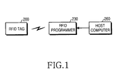
- FIG. 1 is a block diagram illustrating a configuration of a system for programming an RFID tag on a contactless basis. As illustrated in FIG. 1, an
RFID programmer 230 transmits a programming protocol to an RFID tag (or RFID transponder) 200 in a predetermined waveform, and theRFID tag 200 updates RFID data stored therein in response to the programming protocol. - For example, a contactless programming system can be implemented with PG103001, a contactless programming tool (or programmer) for an RFID tag, which is one of MCRF 2XX series by Microchip™, and RFLAB™, which is user interface software. RFLAB™ is installed in a
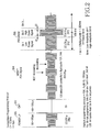
host computer 260 and is a program for controlling theRFID programmer 230 and following a user's commands. - FIG. 2 is a diagram illustrating a signal waveform of a programming protocol in the contactless RFID tag programming system illustrated in FIG. 1. FIG. 2 illustrates a signal waveform of a protocol for programming a programmable RFID tag, e.g., MCRF 200 by Microchip™. More specifically, the illustrated programming protocol has a carrier frequency of 125KHz and a unit time of 8µs.
Reference numeral 300 represents a power-up signal transmitted from theRFID programmer 230 to theRFID tag 200. The power-upsignal 300 provides electric power from theRFID programmer 230 to theRFID tag 200.Reference numeral 302 represents a gap period. TheRFID tag 200 applies internal electric power to its components in response to the power-up signal 300, and a time period for which such an operation is performed correspond to thegap 302.Reference numeral 304 represents a verification signal. TheRFID tag 200, in response to the power-up signal 300, FSK (Frequency Shift Keying)-modulates theverification signal 304 and transmits the FSK-modulatedverification signal 304 to theRFID programmer 230. The FSK-modulatedverification signal 304 indicates that theRFID tag 200 is in a programmable state.Reference numeral 306 represents a programming signal. - Upon receiving the
verification signal 304, theRFID programmer 230 transmits theprogramming signal 306 to theRFID tag 200 according to a predetermined protocol rule. Theprogramming signal 306 illustrated in FIG. 2 is formed of a digital signal, which represents a low amplitude bit with '1' and a high amplitude bit with '0'. - Such a conventional RFID tag programming scheme has several disadvantages. In the contact programming scheme, RFID data recorded during manufacturing of an RFID tag cannot be changed after the product comes into the market. Additionally, in the contactless programming scheme, propriety devices such as the
RFIC programmer 230 and thehost computer 260 must be provided, and an RF signal must be transmitted in the signal waveform of FIG. 2. Therefore, when signal degradation occurs due to a change in an RF environment, the contactless programming scheme is difficult to support stable programming. To guarantee the contactless programming protocol of FIG. 2, an initial power-up signal must maintain a voltage of about 22V If the initial power-up signal fails to hold this voltage, the programming is not initiated. - U.S. patent No. 5,712,628 issued to Phillips et al. discloses a digitally programmable radio module. Although U.S. patent No. 5,712,628 discloses a system applicable to various radio frequencies and signal formats, a circuit structure of an RFID tag disadvantageously becomes complicated, in order to make it possible to program the RFID tag under various conditions. In addition, the patent contains no mention of unification between a mobile communication terminal and an RFID tag.
- EP 1029421 discloses a system in which an ID card connected to a mobile communication terminal has at least one non-mobile ID. However, the plurality of circuits are not integrated into one circuit, and the patent does not mention how to program ID data.
- It is, therefore, the object of the present invention to provide a method for easily programming RFID tag data so that a user can efficiently use various services.
- This object is solved by the subject matters of the independent claims.
- Preferred embodiments are defined in the dependent claims.
- It is an aspect of the present invention to provide a method for stabilizing a programming environment using a circuit of a stabilized mobile communication terminal instead of introducing a propriety programmer for updating RFID tag data.
- It is another aspect of the present invention to provide a mobile communication terminal combined with an RFID tag, for easily programming the RFID tag.
- In accordance with one aspect of the present invention, there is provided a mobile communication terminal comprising: a radio frequency identification (RFID) receiver for receiving RFID data in a first format; an operation device for converting the RFID data in the first format into a second format; a memory for storing the RFID data in the second format; a codec for encoding RFID data stored in the memory; a modulator for RFID-modulating data output from the codec; and an RFID transmitter for transmitting data output from the modulator to an RFID reader.
- In accordance with another aspect of the present invention, there is provided a method for performing radio frequency identification (RFID) in a mobile communication terminal with an RFID function, comprising the steps of: receiving an RFID signal; extracting only RFID data from the received RFID signal; converting a format of the RFID data into a serial protocol format; and storing the converted RFID data in a memory.
- The above features and advantages of the present invention will become more apparent from the following detailed description when taken in conjunction with the accompanying drawings in which:
- FIG. 1 is a block diagram illustrating a configuration of a system for programming an RFID tag on a contactless basis;
- FIG. 2 is a diagram illustrating a signal waveform of a programming protocol in the contactless RFID tag programming system illustrated in FIG. 1;
- FIG. 3A is a block diagram illustrating a structure of an RFID tag programming system according to an embodiment of the present invention;
- FIG. 3B is a block diagram illustrating a structure of a mobile communication terminal with the RFID function illustrated in FIG. 3A;
- FIG. 4 is a diagram illustrating an RFID signal format defined in an RFID standard;
- FIG. 5 is a diagram illustrating an RFID signal with a format that is converted using a programming protocol in a mobile communication terminal according to an embodiment of the present invention; and
- FIG. 6 is a flowchart illustrating a method for implementing RFID programming in a mobile communication terminal with an RFID function according to an embodiment of the present invention.
-
- Preferred embodiments of the present invention will now be described in detail with reference to the annexed drawings. In the drawings, the same or similar elements are denoted by the same reference numerals even though they are depicted in different drawings. In the following description, a detailed description of known functions and configurations incorporated herein has been omitted for conciseness.
- In the following description, the term "RFID programming" indicates an operation of newly storing or updating RFID data provided from the exterior (base station, server, host computer, user, etc.) in a memory so that a mobile communication terminal can perform an RFID function.
- FIG. 3A is a block diagram illustrating a structure of an RFID tag programming system according to an embodiment of the present invention. Referring to FIG. 3A, a
mobile communication terminal 102 receives RFID-related information to be newly stored or updated, from ahost computer 104, and stores the received information in its memory (not shown) to thereby support an RFID function. Thehost computer 104 is provided with the RFID-related information from abase station 106 or an RFID data server. - Unlike the illustrated example, a mobile communication terminal may read data by directly accessing a base station or an authority managing RFID data on a wired or wireless basis without a host computer intervening therebetween. In addition, a user may directly input and program RFID data using an input means such as a keypad through proper authentication or even without authentication.
- FIG. 3B is a block diagram illustrating a structure of a mobile communication terminal with the RFID function illustrated in FIG. 3A. Referring to FIG. 3B, a main processing unit (MPU) 170 of the mobile communication terminal includes the various components of an RFID tag, i.e., an
RFID codec 126 and anRFID modulator 128. Amemory 118stores RFID data 78, and can be implemented with an electrically erasable and programmable read-only memory (EEPROM). Commonly, the EEPROM stores user defined values such as initially set values for an RF module, a display and a voice volume, a password and directory data, or wireless application protocol (WAP) data. However, as the latest flash ROM increases in its capacity, data stored in the low-speed EEPROM tends to be stored in the high-speed flash ROM. Therefore, it is common that the EEPROM has an enough space for storing surplus data. Therefore, it is profitable to store RFID data in the idle space. - A
first clock generator 116 generates a system clock SCLK, and provides the generated system clock SCLK to anMPU core 132 and thememory 118. Asecond clock generator 134 divides the system clock SCLK, or a source clock, into several clocks, and provides appropriate clocks to their respective peripheral components. - The
RFID modulator 128 can be easily implemented within theMPU 170. Modulation schemes used in RFID technology include frequency shift keying (FSK) and phase shift keying (PSK). Theses are lower in complexity than a modulation scheme for a conventional cellular mobile communication system, e.g., Gaussian minimum shift keying (GMSK), which is a modulation scheme used in a GSM (Global System for Mobile communication) mobile communication system, so they can be easily implemented through conventional related logic and technology. Also, theRFID codec 126 is lower in complexity and simpler in implementation than coding for the conventional cellular mobile communication. - An interrupt
port 130 detects approach of an RFID reader (not shown), and notifies the approach to theMPU core 132, which is a main processing unit of theMPU 170. Upon detecting approach of the RFID reader through the interruptport 130, theMPU core 132 issues a command to deliver RFID data stored in thememory 118 to theRFID codec 126 directly or through a memory management unit (MMU, not shown). TheRFID codec 126 receiving the RFID data encodes the received RFID data and delivers the encoded RFID data to theRFID modulator 128. TheRFID modulator 128 modulates the encoded RFID data and delivers the modulated RFID data to the RFID reader via anantenna coil 124. - A
system connector 120 controls interfacing with ahost computer 104 to which the mobile communication system is connected, and battery recharging. Thesystem connector 120 delivers serial digital data transmitted from the host )computer 104, to theMPU core 132, and the serial digital data is stored in thememory 118. - The
RFID programmer 230 and thehost computer 260 illustrated in FIG. 1 have, for example, 9600 baud rate, 8 data bits, and 1 stop bit, and perform communication through a no-parity RS-232 serial interface. Likewise, thesystem connector 120 of FIG. 3B also supports the RS-232 serial interface, and makes serial digital data communication between thehost computer 104 and themobile communication terminal 102 illustrated in FIG. 3B possible. - An
RF module 114 is provided for transmitting and receiving radio signals. In this embodiment of the present invention, themobile communication terminal 102 can receive RFID data from abase station 106 via theRF module 114. - An
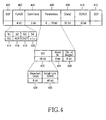
input module 113 acts as a user interface means, and for example, a general keypad or an on-screen keypad can be used as theinput module 113. In this embodiment of the present invention, a user can personally input RFID data using the keypad. - FIG. 4 is a diagram illustrating an RFID signal format defined in an RFID standard. For example, FIG. 4 illustrates an RFID signal format defined in ISO 14223. There are several types of RFID data delivered from a host computer to a mobile communication terminal for RFID programming. The RFID technology supports various standards for application services: ISO 11784/11785/14223 for animal identification; ISO 14223 for an advanced transponder; ISO 10536 for a closed coupling smart card; ISO 14443 for a proximity coupling smart card; and ISO 15693 for a vicinity coupling smart card.
- Referring to FIG. 4,
SOF 400 andEOF 412 are bits indicating a start and an end of a signal, respectively.Command 404, comprised of 5 bits, can generate 32 types of commands. Command codes #00 ∼ #19 are already defined in the standard, and command codes #20 ∼ #31 can be freely changed by a chip maker.Parameters 406 is comprised of 6 - 76 bits, in which aBlock Number 424 and Number-of-Blocks 426 indicate an address of thememory 118 where data is to be stored. InParameters 406, SID (Serial IDentification) 422 represents an address of a particular RFID reader and can be implemented so that it is activated when an ADR (Address) bit 416 ofFLAGS 402 is set to, for example, '1'. 4bits FLAGS 402 represent options, and out of these bits, CRCT (CRC detecTion) 418 indicates use of 16-bit CRC (Cyclic Redundancy Check) 410 andSEL 414 indicates selection of a reader in a special selection state. - RFID data and additional information, such as
Command 404,FLAGS 402 andCRC 410 for transmitting the RFID data, are added to the illustrated RFID signal. - However, in the embodiment of the present invention, the
MPU core 132 can extract only the RFID data, i.e., 32-bit Data 408 illustrated in FIG. 4, and store it in thememory 118, because as components of the RFID tag are integrated into the mobile communication terminal, conventionally required information, e.g.,CRC 410 and FLAGS 402, that was necessary for stable transmission ofData 408 becomes unnecessary. - The
MPU core 132 of the mobile communication terminal extracts only RFID data from a RFID signal delivered in a first format (e.g., FIG. 4), converts the extracted RFID data into a second format (e.g., FIG. 5), and provides the converted RFID data to thememory 118. - FIG. 5 is a diagram illustrating an RFID signal with a format that has been converted using a programming protocol in a mobile communication terminal according to an embodiment of the present invention. In this embodiment, RFID data is divided into a plurality of blocks using an I2C programming protocol, i.e., a typical programming protocol, and then delivered from the
MPU core 132 to thememory 118. - Four bits following a
start bit 500 constitute a control code, and the control code depends upon a unique model of thememory 118. Three bits following the control code are chip select bits, and designate a slave where programming is to be performed, e.g., thememory 118 in the embodiment of the present invention, among the devices supporting the I2C programming protocol, which can be connected to theMPU core 132. In FIG. 5, the control code and the chips select bits are included incontrol byte 502. The one bit following the chip select bits is a read/write bit, and is set to '0' in a programming operation. AnACK bit 504 is used to indicate that data reception from thememory 118 is 'good'. - In this protocol, a single bidirectional serial data (SDA) line is used.
Address High Byte 506 andAddress Low Byte 508 are data fields used by theMPU core 132 to informing thememory 118 of an address where the RFID data is to be written, based on a memory map of theMPU core 132. - In FIG. 4, 32 bits are transmitted at once without discrimination. However, in FIG. 5, the RFID information is divided into four 8-
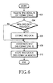
bit blocks - FIG. 6 is a flowchart illustrating a method for implementing RFID programming in a mobile communication terminal with an RFID function according to an embodiment of the present invention. Referring to FIG. 6, in
step 602, theMPU core 132 receives an RFID signal in a first format. Here, the first format represents, for example, the format illustrated in FIG. 4. Instep 604, theMPU core 132 determines whether non-RFID data is included in the RFID signal. If additional information is included in the RFID signal, theMPU core 132 extracts only RFID data from the RFID signal instep 606. Instep 608, theMPU core 132 converts the extracted or received RFID data into a second format. Here, the second format refers to, for example, the format illustrated in FIG. 5. Instep 610, theMPU core 132 stores the RFID data in the second format in a predetermined area of thememory 118, completing the RFID programming. - As described above, in performing RFID programming, the new mobile communication system combined with an RFID tag does not require a separate propriety programming device. This contributes to cost reduction as well as user convenience. In addition, use of the stabilized mobile communication terminal contributes to stabilization of a programming environment. Moreover, because a readable/writable memory in the mobile communication terminal is used as an area for storing RFID data, it is possible to program the RFID data even after the product comes into the market.
- While the present invention has been shown and described with reference to certain preferred embodiments thereof, it will be understood by those skilled in the art that various changes in form and details may be made therein without departing from the scope of the present invention as defined by the appended claims.
Claims (15)
- A mobile communication terminal comprising:a radio frequency identification receiver for receiving a radio frequency identification signal;an operation device for converting radio frequency identification data to a predetermined format;a memory for storing the format-converted radio frequency identification data; anda radio frequency identification transmitter for transmitting the radio frequency identification data to a radio frequency identification reader.
- The mobile communication terminal of claim 1, wherein the operation device is adapted for extracting radio frequency identification data from the received radio frequency identification signal.
- The mobile communication terminal of claim 1 or 2, wherein the predetermined format is a serial protocol format for dividing the radio frequency identification data into a plurality of sub-areas before transmission.
- The mobile communication terminal of claim 1, wherein the received radio frequency identification signal comprises radio frequency identification data in a first format.
- The mobile communication terminal of claim 4, wherein said operation device is adapted for converting said radio frequency identification data in the first format to said predetermined format.
- The mobile communication terminal of claim 5, wherein said predetermined format is a second format.
- The mobile communication terminal of claim 6, comprising a codec for encoding radio frequency identification data stored in the memory.
- The mobile communication terminal of claim 7, further comprising a modulator for radio frequency identification-modulating the encoded data output from the codec.
- The mobile communication terminal of claim 8, wherein the transmitter is adapted for transmitting the modulated data output from the modulator to the radio frequency identification reader.
- The mobile communication terminal of claim 9, wherein the first format is defined to compile the radio frequency identification data in one data area at once before transmission, and the second format is a serial protocol for dividing the radio frequency identification data into a predetermined number of sub-areas before transmission.
- The mobile communication terminal of claim 9 or 10, wherein the memory comprises an electrically erasable and programmable read-only memory.
- The mobile communication terminal of one of claims 9 to 11, wherein the radio frequency identification data is received from a host computer, and the radio frequency identification receiver includes a system connector for communicating with the host computer.
- The mobile communication terminal of one of claims 9 to 11, wherein the radio frequency identification receiver receives the radio frequency identification data from a base station.
- The mobile communication terminal of one of claims 9 to 13, wherein the radio frequency identification receiver receives the radio frequency identification data input by a user.
- A method for performing radio frequency identification in a mobile communication terminal including a radio frequency identification function, comprising the steps of:receiving a radio frequency identification signal;extracting radio frequency identification data from the received radio frequency identification signal;converting a format of the radio frequency identification data into a serial protocol format; andstoring the converted radio frequency identification data in a memory.
Applications Claiming Priority (2)
| Application Number | Priority Date | Filing Date | Title |
|---|---|---|---|
| KR2003075652 | 2003-10-28 | ||
| KR1020030075652A KR20050040451A (en) | 2003-10-28 | 2003-10-28 | Mobile terminal equipment having radio frequency identification function and programming method thereof |
Publications (2)
| Publication Number | Publication Date |
|---|---|
| EP1528768A2 true EP1528768A2 (en) | 2005-05-04 |
| EP1528768A3 EP1528768A3 (en) | 2008-01-23 |
Family
ID=34420680
Family Applications (1)
| Application Number | Title | Priority Date | Filing Date |
|---|---|---|---|
| EP04011835A Withdrawn EP1528768A3 (en) | 2003-10-28 | 2004-05-18 | Mobile communication terminal with RFID function and RFID programming method in the same |
Country Status (5)
| Country | Link |
|---|---|
| US (1) | US20050088285A1 (en) |
| EP (1) | EP1528768A3 (en) |
| JP (1) | JP3993187B2 (en) |
| KR (1) | KR20050040451A (en) |
| CN (1) | CN1612494A (en) |
Cited By (3)
| Publication number | Priority date | Publication date | Assignee | Title |
|---|---|---|---|---|
| WO2007025518A1 (en) * | 2005-08-30 | 2007-03-08 | Gavitec Ag | Method for supplying and using data, communication device for using such data, and use of visual and/or acoustic output means |
| US7391328B2 (en) * | 2005-02-05 | 2008-06-24 | Compal Electronics, Inc. | Radio frequency identification system |
| FR3024257A1 (en) * | 2014-07-24 | 2016-01-29 | Sagem Defense Securite | IMPROVED RFID LABEL |
Families Citing this family (94)
| Publication number | Priority date | Publication date | Assignee | Title |
|---|---|---|---|---|
| US10835307B2 (en) | 2001-06-12 | 2020-11-17 | Ethicon Llc | Modular battery powered handheld surgical instrument containing elongated multi-layered shaft |
| US8127984B2 (en) * | 2003-06-13 | 2012-03-06 | Varia Holdings Llc | Emulated radio frequency identification |
| WO2006074150A1 (en) * | 2005-01-03 | 2006-07-13 | Falkin Systems, Llc | Method, system and device for identification from multiple data inputs |
| CN100527159C (en) * | 2005-10-31 | 2009-08-12 | 深圳华为通信技术有限公司 | Storage card and terminal equipment combining storage card |
| KR100656209B1 (en) * | 2005-11-28 | 2006-12-13 | 삼성전자주식회사 | Method and apparatus for detecting end of response signal on radio frequency identifier tag |
| JP5008384B2 (en) * | 2005-12-02 | 2012-08-22 | 株式会社半導体エネルギー研究所 | Semiconductor device |
| KR100718012B1 (en) * | 2005-12-30 | 2007-05-14 | (주)한창시스템 | Battery pack for mobile communication terminal and near field communication method using the same |
| KR100756179B1 (en) * | 2006-01-09 | 2007-09-05 | 주식회사 팬택 | A mobile communication terminal having a active rfid transponer |
| US8244747B2 (en) * | 2006-12-05 | 2012-08-14 | International Business Machines Corporation | Middleware for query processing across a network of RFID databases |
| US9089360B2 (en) | 2008-08-06 | 2015-07-28 | Ethicon Endo-Surgery, Inc. | Devices and techniques for cutting and coagulating tissue |
| US8890660B2 (en) | 2009-03-24 | 2014-11-18 | Nxp B.V. | Power saving method |
| US8663220B2 (en) | 2009-07-15 | 2014-03-04 | Ethicon Endo-Surgery, Inc. | Ultrasonic surgical instruments |
| US8290463B2 (en) * | 2009-09-14 | 2012-10-16 | ConvenientPower HK Ltd. | Universal demodulation and modulation for data communication in wireless power transfer |
| US8951248B2 (en) | 2009-10-09 | 2015-02-10 | Ethicon Endo-Surgery, Inc. | Surgical generator for ultrasonic and electrosurgical devices |
| US10441345B2 (en) | 2009-10-09 | 2019-10-15 | Ethicon Llc | Surgical generator for ultrasonic and electrosurgical devices |
| US11090104B2 (en) | 2009-10-09 | 2021-08-17 | Cilag Gmbh International | Surgical generator for ultrasonic and electrosurgical devices |
| US8469981B2 (en) | 2010-02-11 | 2013-06-25 | Ethicon Endo-Surgery, Inc. | Rotatable cutting implement arrangements for ultrasonic surgical instruments |
| US8957763B2 (en) | 2010-07-09 | 2015-02-17 | Cypress Semiconductor Corporation | RFID access method using an indirect memory pointer |
| US8686836B2 (en) | 2010-07-09 | 2014-04-01 | Cypress Semiconductor Corporation | Fast block write using an indirect memory pointer |
| US9846664B2 (en) * | 2010-07-09 | 2017-12-19 | Cypress Semiconductor Corporation | RFID interface and interrupt |
| US8723654B2 (en) * | 2010-07-09 | 2014-05-13 | Cypress Semiconductor Corporation | Interrupt generation and acknowledgment for RFID |
| US9092582B2 (en) * | 2010-07-09 | 2015-07-28 | Cypress Semiconductor Corporation | Low power, low pin count interface for an RFID transponder |
| US8795327B2 (en) | 2010-07-22 | 2014-08-05 | Ethicon Endo-Surgery, Inc. | Electrosurgical instrument with separate closure and cutting members |
| US9192431B2 (en) | 2010-07-23 | 2015-11-24 | Ethicon Endo-Surgery, Inc. | Electrosurgical cutting and sealing instrument |
| CN102446280B (en) * | 2010-09-30 | 2016-03-23 | 西门子公司 | A kind of method of verification msg, Apparatus and system |
| US20140225804A1 (en) * | 2011-03-03 | 2014-08-14 | Checkpoint Systems, Inc. | Multiplexed antenna localizing |
| US9259265B2 (en) | 2011-07-22 | 2016-02-16 | Ethicon Endo-Surgery, Llc | Surgical instruments for tensioning tissue |
| EP2811932B1 (en) | 2012-02-10 | 2019-06-26 | Ethicon LLC | Robotically controlled surgical instrument |
| US9226766B2 (en) * | 2012-04-09 | 2016-01-05 | Ethicon Endo-Surgery, Inc. | Serial communication protocol for medical device |
| US9439668B2 (en) | 2012-04-09 | 2016-09-13 | Ethicon Endo-Surgery, Llc | Switch arrangements for ultrasonic surgical instruments |
| US20140005705A1 (en) | 2012-06-29 | 2014-01-02 | Ethicon Endo-Surgery, Inc. | Surgical instruments with articulating shafts |
| US9198714B2 (en) | 2012-06-29 | 2015-12-01 | Ethicon Endo-Surgery, Inc. | Haptic feedback devices for surgical robot |
| US9351754B2 (en) | 2012-06-29 | 2016-05-31 | Ethicon Endo-Surgery, Llc | Ultrasonic surgical instruments with distally positioned jaw assemblies |
| US9393037B2 (en) | 2012-06-29 | 2016-07-19 | Ethicon Endo-Surgery, Llc | Surgical instruments with articulating shafts |
| US9326788B2 (en) | 2012-06-29 | 2016-05-03 | Ethicon Endo-Surgery, Llc | Lockout mechanism for use with robotic electrosurgical device |
| US9408622B2 (en) | 2012-06-29 | 2016-08-09 | Ethicon Endo-Surgery, Llc | Surgical instruments with articulating shafts |
| US9226767B2 (en) | 2012-06-29 | 2016-01-05 | Ethicon Endo-Surgery, Inc. | Closed feedback control for electrosurgical device |
| US20140005702A1 (en) | 2012-06-29 | 2014-01-02 | Ethicon Endo-Surgery, Inc. | Ultrasonic surgical instruments with distally positioned transducers |
| US9492224B2 (en) | 2012-09-28 | 2016-11-15 | EthiconEndo-Surgery, LLC | Multi-function bi-polar forceps |
| US9095367B2 (en) | 2012-10-22 | 2015-08-04 | Ethicon Endo-Surgery, Inc. | Flexible harmonic waveguides/blades for surgical instruments |
| US20140135804A1 (en) | 2012-11-15 | 2014-05-15 | Ethicon Endo-Surgery, Inc. | Ultrasonic and electrosurgical devices |
| US9814514B2 (en) | 2013-09-13 | 2017-11-14 | Ethicon Llc | Electrosurgical (RF) medical instruments for cutting and coagulating tissue |
| US9265926B2 (en) | 2013-11-08 | 2016-02-23 | Ethicon Endo-Surgery, Llc | Electrosurgical devices |
| GB2521228A (en) | 2013-12-16 | 2015-06-17 | Ethicon Endo Surgery Inc | Medical device |
| US9795436B2 (en) | 2014-01-07 | 2017-10-24 | Ethicon Llc | Harvesting energy from a surgical generator |
| US9554854B2 (en) | 2014-03-18 | 2017-01-31 | Ethicon Endo-Surgery, Llc | Detecting short circuits in electrosurgical medical devices |
| US10463421B2 (en) | 2014-03-27 | 2019-11-05 | Ethicon Llc | Two stage trigger, clamp and cut bipolar vessel sealer |
| US10092310B2 (en) | 2014-03-27 | 2018-10-09 | Ethicon Llc | Electrosurgical devices |
| US9737355B2 (en) | 2014-03-31 | 2017-08-22 | Ethicon Llc | Controlling impedance rise in electrosurgical medical devices |
| US9913680B2 (en) | 2014-04-15 | 2018-03-13 | Ethicon Llc | Software algorithms for electrosurgical instruments |
| US10285724B2 (en) | 2014-07-31 | 2019-05-14 | Ethicon Llc | Actuation mechanisms and load adjustment assemblies for surgical instruments |
| US10639092B2 (en) | 2014-12-08 | 2020-05-05 | Ethicon Llc | Electrode configurations for surgical instruments |
| US10245095B2 (en) | 2015-02-06 | 2019-04-02 | Ethicon Llc | Electrosurgical instrument with rotation and articulation mechanisms |
| US10321950B2 (en) | 2015-03-17 | 2019-06-18 | Ethicon Llc | Managing tissue treatment |
| US10342602B2 (en) | 2015-03-17 | 2019-07-09 | Ethicon Llc | Managing tissue treatment |
| US10595929B2 (en) | 2015-03-24 | 2020-03-24 | Ethicon Llc | Surgical instruments with firing system overload protection mechanisms |
| US10898256B2 (en) | 2015-06-30 | 2021-01-26 | Ethicon Llc | Surgical system with user adaptable techniques based on tissue impedance |
| US10034704B2 (en) | 2015-06-30 | 2018-07-31 | Ethicon Llc | Surgical instrument with user adaptable algorithms |
| US11051873B2 (en) | 2015-06-30 | 2021-07-06 | Cilag Gmbh International | Surgical system with user adaptable techniques employing multiple energy modalities based on tissue parameters |
| US10765470B2 (en) | 2015-06-30 | 2020-09-08 | Ethicon Llc | Surgical system with user adaptable techniques employing simultaneous energy modalities based on tissue parameters |
| US11129669B2 (en) | 2015-06-30 | 2021-09-28 | Cilag Gmbh International | Surgical system with user adaptable techniques based on tissue type |
| US10687884B2 (en) | 2015-09-30 | 2020-06-23 | Ethicon Llc | Circuits for supplying isolated direct current (DC) voltage to surgical instruments |
| US10595930B2 (en) | 2015-10-16 | 2020-03-24 | Ethicon Llc | Electrode wiping surgical device |
| US10179022B2 (en) | 2015-12-30 | 2019-01-15 | Ethicon Llc | Jaw position impedance limiter for electrosurgical instrument |
| US10575892B2 (en) | 2015-12-31 | 2020-03-03 | Ethicon Llc | Adapter for electrical surgical instruments |
| US11229471B2 (en) | 2016-01-15 | 2022-01-25 | Cilag Gmbh International | Modular battery powered handheld surgical instrument with selective application of energy based on tissue characterization |
| US10251664B2 (en) | 2016-01-15 | 2019-04-09 | Ethicon Llc | Modular battery powered handheld surgical instrument with multi-function motor via shifting gear assembly |
| US11129670B2 (en) | 2016-01-15 | 2021-09-28 | Cilag Gmbh International | Modular battery powered handheld surgical instrument with selective application of energy based on button displacement, intensity, or local tissue characterization |
| US10716615B2 (en) | 2016-01-15 | 2020-07-21 | Ethicon Llc | Modular battery powered handheld surgical instrument with curved end effectors having asymmetric engagement between jaw and blade |
| US10555769B2 (en) | 2016-02-22 | 2020-02-11 | Ethicon Llc | Flexible circuits for electrosurgical instrument |
| US10646269B2 (en) | 2016-04-29 | 2020-05-12 | Ethicon Llc | Non-linear jaw gap for electrosurgical instruments |
| US10485607B2 (en) | 2016-04-29 | 2019-11-26 | Ethicon Llc | Jaw structure with distal closure for electrosurgical instruments |
| US10702329B2 (en) | 2016-04-29 | 2020-07-07 | Ethicon Llc | Jaw structure with distal post for electrosurgical instruments |
| US10456193B2 (en) | 2016-05-03 | 2019-10-29 | Ethicon Llc | Medical device with a bilateral jaw configuration for nerve stimulation |
| US10376305B2 (en) | 2016-08-05 | 2019-08-13 | Ethicon Llc | Methods and systems for advanced harmonic energy |
| US11266430B2 (en) | 2016-11-29 | 2022-03-08 | Cilag Gmbh International | End effector control and calibration |
| CN107426398B (en) * | 2017-04-21 | 2021-03-30 | 深圳市海恒通科技有限公司 | Intercom implementation method, intercom accessory and intercom implementation system for mobile terminal |
| US20210196349A1 (en) | 2019-12-30 | 2021-07-01 | Ethicon Llc | Electrosurgical instrument with flexible wiring assemblies |
| US11779387B2 (en) | 2019-12-30 | 2023-10-10 | Cilag Gmbh International | Clamp arm jaw to minimize tissue sticking and improve tissue control |
| US11696776B2 (en) | 2019-12-30 | 2023-07-11 | Cilag Gmbh International | Articulatable surgical instrument |
| US11937866B2 (en) | 2019-12-30 | 2024-03-26 | Cilag Gmbh International | Method for an electrosurgical procedure |
| US11950797B2 (en) | 2019-12-30 | 2024-04-09 | Cilag Gmbh International | Deflectable electrode with higher distal bias relative to proximal bias |
| US11786294B2 (en) | 2019-12-30 | 2023-10-17 | Cilag Gmbh International | Control program for modular combination energy device |
| US11684412B2 (en) | 2019-12-30 | 2023-06-27 | Cilag Gmbh International | Surgical instrument with rotatable and articulatable surgical end effector |
| US11911063B2 (en) | 2019-12-30 | 2024-02-27 | Cilag Gmbh International | Techniques for detecting ultrasonic blade to electrode contact and reducing power to ultrasonic blade |
| US11779329B2 (en) | 2019-12-30 | 2023-10-10 | Cilag Gmbh International | Surgical instrument comprising a flex circuit including a sensor system |
| US11660089B2 (en) | 2019-12-30 | 2023-05-30 | Cilag Gmbh International | Surgical instrument comprising a sensing system |
| US11937863B2 (en) | 2019-12-30 | 2024-03-26 | Cilag Gmbh International | Deflectable electrode with variable compression bias along the length of the deflectable electrode |
| US11452525B2 (en) | 2019-12-30 | 2022-09-27 | Cilag Gmbh International | Surgical instrument comprising an adjustment system |
| US11944366B2 (en) | 2019-12-30 | 2024-04-02 | Cilag Gmbh International | Asymmetric segmented ultrasonic support pad for cooperative engagement with a movable RF electrode |
| US20210196361A1 (en) | 2019-12-30 | 2021-07-01 | Ethicon Llc | Electrosurgical instrument with monopolar and bipolar energy capabilities |
| US11786291B2 (en) | 2019-12-30 | 2023-10-17 | Cilag Gmbh International | Deflectable support of RF energy electrode with respect to opposing ultrasonic blade |
| US11812957B2 (en) | 2019-12-30 | 2023-11-14 | Cilag Gmbh International | Surgical instrument comprising a signal interference resolution system |
| CN112001460B (en) * | 2020-07-16 | 2022-04-01 | 中国科学院微电子研究所 | Signal processing method and device and RFID system |
Citations (2)
| Publication number | Priority date | Publication date | Assignee | Title |
|---|---|---|---|---|
| CA2368377A1 (en) * | 1999-04-07 | 2000-10-19 | Swisscom Mobile Ag | Method and system for ordering, loading and using access tickets |
| WO2002073522A1 (en) * | 2001-03-13 | 2002-09-19 | Stmicroelectronics Sa | Control signal-adaptive contactless chip card |
Family Cites Families (15)
| Publication number | Priority date | Publication date | Assignee | Title |
|---|---|---|---|---|
| US4075632A (en) * | 1974-08-27 | 1978-02-21 | The United States Of America As Represented By The United States Department Of Energy | Interrogation, and detection system |
| US4360810A (en) * | 1981-01-19 | 1982-11-23 | The United States Of America As Represented By The United States Department Of Energy | Multichannel homodyne receiver |
| US4786907A (en) * | 1986-07-14 | 1988-11-22 | Amtech Corporation | Transponder useful in a system for identifying objects |
| US4739328A (en) * | 1986-07-14 | 1988-04-19 | Amtech Corporation | System for identifying particular objects |
| US4782345A (en) * | 1986-07-29 | 1988-11-01 | Amtech Corporation | Transponder antenna |
| US4835377A (en) * | 1987-06-10 | 1989-05-30 | Brown Richard R | Programmer for identification system |
| US4816839A (en) * | 1987-12-18 | 1989-03-28 | Amtech Corporation | Transponder antenna |
| US4853705A (en) * | 1988-05-11 | 1989-08-01 | Amtech Technology Corporation | Beam powered antenna |
| US5483827A (en) * | 1994-06-03 | 1996-01-16 | Computer Methods Corporation | Active integrated circuit transponder and sensor apparatus for sensing and transmitting vehicle tire parameter data |
| US5712628A (en) * | 1995-08-31 | 1998-01-27 | Northrop Grumman Corporation | Digitally programmable radio modules for transponder systems |
| US5995898A (en) * | 1996-12-06 | 1999-11-30 | Micron Communication, Inc. | RFID system in communication with vehicle on-board computer |
| EP1026627A1 (en) * | 1999-01-29 | 2000-08-09 | Siemens Aktiengesellschaft | Contactless data communication system and method |
| US6608551B1 (en) * | 1999-09-13 | 2003-08-19 | Intermec Ip Corp | Low-cost radio replacement utilizing RFID technology |
| US7009515B2 (en) * | 2001-04-11 | 2006-03-07 | Battelle Memorial Institute K1-53 | Frequency-hopping RFID system |
| US7175093B2 (en) * | 2001-05-16 | 2007-02-13 | Symbol Technologies, Inc. | Range extension for RFID hand-held mobile computers |
-
2003
- 2003-10-28 KR KR1020030075652A patent/KR20050040451A/en not_active Application Discontinuation
-
2004
- 2004-04-27 US US10/833,254 patent/US20050088285A1/en not_active Abandoned
- 2004-05-18 EP EP04011835A patent/EP1528768A3/en not_active Withdrawn
- 2004-05-20 CN CNA2004100458783A patent/CN1612494A/en active Pending
- 2004-08-19 JP JP2004239942A patent/JP3993187B2/en not_active Expired - Fee Related
Patent Citations (2)
| Publication number | Priority date | Publication date | Assignee | Title |
|---|---|---|---|---|
| CA2368377A1 (en) * | 1999-04-07 | 2000-10-19 | Swisscom Mobile Ag | Method and system for ordering, loading and using access tickets |
| WO2002073522A1 (en) * | 2001-03-13 | 2002-09-19 | Stmicroelectronics Sa | Control signal-adaptive contactless chip card |
Cited By (3)
| Publication number | Priority date | Publication date | Assignee | Title |
|---|---|---|---|---|
| US7391328B2 (en) * | 2005-02-05 | 2008-06-24 | Compal Electronics, Inc. | Radio frequency identification system |
| WO2007025518A1 (en) * | 2005-08-30 | 2007-03-08 | Gavitec Ag | Method for supplying and using data, communication device for using such data, and use of visual and/or acoustic output means |
| FR3024257A1 (en) * | 2014-07-24 | 2016-01-29 | Sagem Defense Securite | IMPROVED RFID LABEL |
Also Published As
| Publication number | Publication date |
|---|---|
| KR20050040451A (en) | 2005-05-03 |
| CN1612494A (en) | 2005-05-04 |
| JP2005136960A (en) | 2005-05-26 |
| JP3993187B2 (en) | 2007-10-17 |
| EP1528768A3 (en) | 2008-01-23 |
| US20050088285A1 (en) | 2005-04-28 |
Similar Documents
| Publication | Publication Date | Title |
|---|---|---|
| EP1528768A2 (en) | Mobile communication terminal with RFID function and RFID programming method in the same | |
| US7374100B2 (en) | Mobile terminal having smart card coupled with RFID tag and method for performing RFID function in such mobile terminal | |
| EP1522955B1 (en) | Mobile terminal circuit including an RFID tag and wireless identification method using the same | |
| US7365642B2 (en) | Semiconductor integrated circuit, mobile module, and message communication method | |
| KR100887083B1 (en) | Ic module and cellular phone | |
| EP2097838B1 (en) | A method for storing data in a rfid transponder | |
| US9003133B2 (en) | Apparatus for storing/reading data in a memory array of a transponder | |
| EP1783660A2 (en) | Memory card and terminal equipment incorporating the same | |
| EP2541791A2 (en) | Systems and methods for providing NFC secure application support in battery-off mode when no nonvolatile memory write access is available | |
| US8362881B2 (en) | Method for storing data as well as a transponder, a read/write-device, a computer readable medium including a program element and such a program element adapted to perform this method | |
| US10931331B2 (en) | Communication device and method | |
| US8698599B2 (en) | Reader/writer, communication processing device, communication processing method, data management system and communication system | |
| KR100926364B1 (en) | Method and Apparatus for Providing Simultaneously Plural Application Interfaces in Smart Card | |
| US20020196786A1 (en) | Method and apparatus for data transmission | |
| CN115204343A (en) | RFID tag IC with standard adaptive counter incrementing and RFID communication system | |
| KR101156155B1 (en) | smart card having zigbee communication function and mobile terminal using it and data processing method thereof | |
| JP2014063310A (en) | Ic card, portable electronic equipment and ic card processor | |
| KR20140142566A (en) | NFC tag supporting hybrid mode and generating method thereof | |
| KR20110053779A (en) | Smartcard, and managment method of rf data in smartcard |
Legal Events
| Date | Code | Title | Description |
|---|---|---|---|
| PUAI | Public reference made under article 153(3) epc to a published international application that has entered the european phase |
Free format text: ORIGINAL CODE: 0009012 |
|
| 17P | Request for examination filed |
Effective date: 20040518 |
|
| AK | Designated contracting states |
Kind code of ref document: A2 Designated state(s): AT BE BG CH CY CZ DE DK EE ES FI FR GB GR HU IE IT LI LU MC NL PL PT RO SE SI SK TR |
|
| AX | Request for extension of the european patent |
Extension state: AL HR LT LV MK |
|
| PUAL | Search report despatched |
Free format text: ORIGINAL CODE: 0009013 |
|
| AK | Designated contracting states |
Kind code of ref document: A3 Designated state(s): AT BE BG CH CY CZ DE DK EE ES FI FR GB GR HU IE IT LI LU MC NL PL PT RO SE SI SK TR |
|
| AX | Request for extension of the european patent |
Extension state: AL HR LT LV MK |
|
| STAA | Information on the status of an ep patent application or granted ep patent |
Free format text: STATUS: THE APPLICATION HAS BEEN WITHDRAWN |
|
| 18W | Application withdrawn |
Effective date: 20080513 |