EP1528446A1 - Verfahren und Regler zum Einstellen eines Stellglieds sowie Verwendung des Reglers - Google Patents
Verfahren und Regler zum Einstellen eines Stellglieds sowie Verwendung des Reglers Download PDFInfo
- Publication number
- EP1528446A1 EP1528446A1 EP03024964A EP03024964A EP1528446A1 EP 1528446 A1 EP1528446 A1 EP 1528446A1 EP 03024964 A EP03024964 A EP 03024964A EP 03024964 A EP03024964 A EP 03024964A EP 1528446 A1 EP1528446 A1 EP 1528446A1
- Authority
- EP
- European Patent Office
- Prior art keywords
- actuator
- controller
- signal
- valve
- positioner
- Prior art date
- Legal status (The legal status is an assumption and is not a legal conclusion. Google has not performed a legal analysis and makes no representation as to the accuracy of the status listed.)
- Withdrawn
Links
Images
Classifications
-
- G—PHYSICS
- G05—CONTROLLING; REGULATING
- G05B—CONTROL OR REGULATING SYSTEMS IN GENERAL; FUNCTIONAL ELEMENTS OF SUCH SYSTEMS; MONITORING OR TESTING ARRANGEMENTS FOR SUCH SYSTEMS OR ELEMENTS
- G05B19/00—Program-control systems
- G05B19/02—Program-control systems electric
- G05B19/18—Numerical control [NC], i.e. automatically operating machines, in particular machine tools, e.g. in a manufacturing environment, so as to execute positioning, movement or co-ordinated operations by means of program data in numerical form
- G05B19/416—Numerical control [NC], i.e. automatically operating machines, in particular machine tools, e.g. in a manufacturing environment, so as to execute positioning, movement or co-ordinated operations by means of program data in numerical form characterised by control of velocity, acceleration or deceleration
-
- F—MECHANICAL ENGINEERING; LIGHTING; HEATING; WEAPONS; BLASTING
- F01—MACHINES OR ENGINES IN GENERAL; ENGINE PLANTS IN GENERAL; STEAM ENGINES
- F01D—NON-POSITIVE DISPLACEMENT MACHINES OR ENGINES, e.g. STEAM TURBINES
- F01D17/00—Regulating or controlling by varying flow
- F01D17/10—Final actuators
- F01D17/12—Final actuators arranged in stator parts
- F01D17/14—Final actuators arranged in stator parts varying effective cross-sectional area of nozzles or guide conduits
- F01D17/141—Final actuators arranged in stator parts varying effective cross-sectional area of nozzles or guide conduits by means of shiftable members or valves obturating part of the flow path
- F01D17/145—Final actuators arranged in stator parts varying effective cross-sectional area of nozzles or guide conduits by means of shiftable members or valves obturating part of the flow path by means of valves, e.g. for steam turbines
-
- G—PHYSICS
- G05—CONTROLLING; REGULATING
- G05B—CONTROL OR REGULATING SYSTEMS IN GENERAL; FUNCTIONAL ELEMENTS OF SUCH SYSTEMS; MONITORING OR TESTING ARRANGEMENTS FOR SUCH SYSTEMS OR ELEMENTS
- G05B2219/00—Program-control systems
- G05B2219/30—Nc systems
- G05B2219/43—Speed, acceleration, deceleration control ADC
- G05B2219/43073—Time controlled opening profile
-
- G—PHYSICS
- G05—CONTROLLING; REGULATING
- G05B—CONTROL OR REGULATING SYSTEMS IN GENERAL; FUNCTIONAL ELEMENTS OF SUCH SYSTEMS; MONITORING OR TESTING ARRANGEMENTS FOR SUCH SYSTEMS OR ELEMENTS
- G05B2219/00—Program-control systems
- G05B2219/30—Nc systems
- G05B2219/45—Nc applications
- G05B2219/45006—Valves
Definitions
- the invention relates to a method and a controller for Adjusting an actuator. It also relates to a Using the controller.
- controllers are used to the process variables of various process engineering Bring processes to specific, desired values and these Values as good as possible. Only then is a safe and secure economic operation of the technical system guaranteed.
- the Regulator quickly intervene and the other should be through they generated control signals a desired temporal behavior demonstrate. In particular, usually has too much overshoot as well as too fast a ruling can be prevented. the latter Problem is for example countered by that the control signal ramped to the actuator becomes; the control signal is fed to a so-called ramp generator, which additionally have a control value limitation can.
- the ramp generator generates a linear until End value of the switched control signal rising further Control signal (which, if necessary, in accordance with its amplitude aforementioned desired manipulated variable limiting limited is) supplied to the actuator.
- the regulation of the Steam mass flow to the steam turbine according to a predetermined, desired behavior. It is usually to maintain an actuating speed with which the steam valve opened to a control value or starting from this to be closed.
- the steam turbine may therefore, for example not abrupt with a large amount of steam be charged.
- the steam valve can be designed, for example, as a valve be, which is actuated via a drive, the on Servo valve is controlled.
- control current as Actuator signal used for the servo valve.
- This current signal is generated by the output signal (which is usually a determined fixed value for Achievement of a desired steam mass flow to the steam turbine is) of the valve position controller in the steam turbine controller by means of a previously mentioned ramp generator to the control signal is further processed for the steam valve.
- the slew rate from the ramp generator of the steam turbine controller generated control signal and its possibly required control value limitation have only been in the commissioning phase so far set the steam turbine controller in the steam power plant.
- the Steam valve has in addition to a servo drive for opening and Include a position transmitter, which in the form of a Current signal the current position in terms of its opening degree to the steam turbine controller reports.
- the steam turbine controller usually the steam valve several times opened for test purposes and closed to the case by the positioner of the steam valve generated current signals attributable to the current opening degree of the steam valve. For example, will the steam valve within a period of time from 1-5 seconds from the completely closed to the complete brought open position and thereby by his positioner recorded generated current signals. It could e.g. for the completely closed position a current of 4 mA, which thereafter, for example, substantially or according to another temporal behavior linear to a final value of e.g. 18 mA increases, which the fully open position corresponds.
- This current characteristic obtained during commissioning is then implemented in the ramp generator of the steam turbine controller, so that in case of operation the steam turbine valve within opened and / or closed for a desired period of time So that can be one from the steam turbine manufacturer required valve actuating speed is maintained.
- a disadvantage of this known method is that the commissioning the steam turbine controller is time consuming because Only on site in the power plant, the adjustment of the control signal for the steam valve at a desired time Behavior, for example, a predetermined valve actuating speed, must take place and in particular a test phase is to be provided.
- the invention is therefore based on the object, a controller and a method for adjusting the position of an actuator specify, by means of which the commissioning of a corresponding control device is simplified.
- the object is achieved according to the invention by a regulator for adjusting the position of an actuator by means of a control signal, wherein a positioner a setpoint and an actual value of a variable to be set the actuator can be supplied and wherein the desired value temporal behavior with respect to the actuating signal imposable and the setpoint to the positioner as timed variable signal can be fed.
- the controller Compared to known regulators, where the adaptation the control signal to a desired temporal behavior, for example, to a valve actuating speed, only at the commissioning of the control device in the technical Plant by means of an aforementioned known method is made is provided in the controller according to the invention, the desired temporal behavior of the actuating signal thereby to realize that this desired temporal behavior is transferred to the setpoint and this setpoint then as a corresponding time-varying signal is fed to the controller.
- a desired temporal behavior for example, to a valve actuating speed
- a dynamic control valve limit which is essentially a ramp generator with adjustable Rise times or cooldowns for opening and closing the actuator comprises.
- These times mentioned can be specified, for example, by time parameters, which e.g. identify the period within which to open and / or close the actuator. there these parameters may be different from each other; it is So possible to specify different speeds, with which the actuator is to open or close.
- controller offers in particular in steam power plants at startup benefits, since There is practically always an operating speed for the Steam valve is prescribed, which must be realized and now already taken into account in the project planning can and not only when commissioning the scheme.
- the controller a P-controller.
- Such a proportional controller is with no time constant Afflicted, so that the time-varying setpoint of This controller is processed undistorted and instantaneously. In this way, the control signal has the desired temporal Behavior with highest accuracy.
- the invention is achieved by a Method for adjusting the position of an actuator by means of an actuating signal, wherein by means of a desired temporal behavior of the actuating signal an operating speed is set for the actuator, with a Setpoint the time behavior of the control signal impressed and the setpoint as a time-varying signal for Forming the actuating signal is formed.
- the time-varying setpoint is preferably a Positioner guided and the control signal by means of the positioner educated.
- the actuation speed the speed with which one Valve is actuated as an actuator.
- the invention further leads to a use of an inventive Regulator at a power plant for adjustment a steam valve.
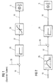
- FIG. 1 shows a regulator according to the prior art, by means of which an actuator 5 is actuated, wherein the actuator is designed as a valve whose electrohydraulic Drive controlled by a servo valve becomes.
- a positioner 25 is the difference of a desired value 15 and an actual value 20 and to a positioner output signal 27 processed.
- the positioner 25 is designed as a proportional controller.
- the Reference value 15 is preferably designed as a signal with at least temporarily constant value.
- the positioner output signal 27 therefore also has a constant value which leads to a desired position the actuator 5, for example, a desired opening degree, corresponds.
- the dynamic limitation 30 is preferably by means of a Ramp generator realized, which optionally additionally an amplitude limitation has, so that the actuating signal 10 only after a certain, predetermined time the value of the positioner output signal 27, the latter Value by possibly limiting the amplitude to one maximum amount is limited.
- the signal conditioning stage 35 thus provides an adapted one Output signal 37 as a time-varying setpoint, which decreases by an actual value 20 as a control difference one Positioner 25 is supplied.
- This positioner 25 generates a time-variable signal as a control signal 10, which an actuator 5, which is preferably formed as a valve driven by a servomotor becomes.
- the signal matching stage 35 can set the desired temporal behavior and the setpoint 15 be imprinted.
- the signal conditioning stage comprises 35 with a ramp generator with adjustable rise or decay times and possibly an amplitude limitation.
- T1 may specify the time period in which the actuator 5 from the fully closed in the fully open position to be brought.
- the parameters T2 and / or T3 may indicate within which Period the actuator 5 from its fully opened to bring in a completely closed position is.
Landscapes
- Engineering & Computer Science (AREA)
- Human Computer Interaction (AREA)
- Manufacturing & Machinery (AREA)
- Physics & Mathematics (AREA)
- General Physics & Mathematics (AREA)
- Automation & Control Theory (AREA)
- Mechanical Engineering (AREA)
- General Engineering & Computer Science (AREA)
- Control Of Turbines (AREA)
Abstract
Description
- FIG 1
- einen Regler nach dem Stand der Technik, und
- FIG 2
- einen erfindungsgemäßen Regler.
Claims (7)
- Regler (1) zum Einstellen der Position eines Stellglieds (5) mittels eines Stellsignals (10), wobei einem Stellungsregler (25) ein Sollwert (15) und ein Istwert (20) einer einzustellenden Größe des Stellglieds (5) zugeführt sind, dadurch gekennzeichnet, dass dem Sollwert (15) ein gewünschtes zeitliches Verhalten bezüglich des Stellsignals (10) aufprägbar und der Sollwert (15) dem Stellungsregler (25) als zeitlich veränderliches Signal zuführbar ist.
- Regler (1) nach Anspruch 1, wobei das Stellglied (5) ein Ventil ist, insbesondere zur Dampfzuleitung zu einer Dampfturbine.
- Regler (1) nach Anspruch 1 oder 2, wobei der Stellungsregler (25) ein P-Regler ist.
- Verfahren zum Einstellen der Position eines Stellglieds (5) mittels eines Stellsignals (10),
dadurch gekennzeichnet, dass mittels eines gewünschten zeitlichen Verhaltens des Stellsignals (10) eine Betätigungsgeschwindigkeit für das Stellglied (5) festgelegt wird, wobei einem Sollwert (15) das zeitliche Verhalten des Stellsignals (10) aufgeprägt wird und der Sollwert (15) als zeitliches veränderliches Signal zur Bildung des Stellsignals (10) verwendet wird. - Verfahren nach Anspruch 4, wobei der zeitveränderliche Sollwert (15) zu einem Stellungsregler (25) geführt wird und das Stellsignals (10) mittels des Stellungsreglers (25) gebildet wird.
- Verfahren nach Anspruch 4, wobei die Betätigungsgeschwindigkeit die Geschwindigkeit ist, mit der ein Ventil als Stellglied betätigt wird.
- Verwendung eines Reglers nach einem der Ansprüche 1 bis 3, bei einer Kraftwerksanlage zur Einstellung eines Dampfventils.
Priority Applications (2)
| Application Number | Priority Date | Filing Date | Title |
|---|---|---|---|
| EP03024964A EP1528446A1 (de) | 2003-10-29 | 2003-10-29 | Verfahren und Regler zum Einstellen eines Stellglieds sowie Verwendung des Reglers |
| US10/977,681 US7295899B2 (en) | 2003-10-29 | 2004-10-28 | Method and controller for setting a control element and a use of said controller |
Applications Claiming Priority (1)
| Application Number | Priority Date | Filing Date | Title |
|---|---|---|---|
| EP03024964A EP1528446A1 (de) | 2003-10-29 | 2003-10-29 | Verfahren und Regler zum Einstellen eines Stellglieds sowie Verwendung des Reglers |
Publications (1)
| Publication Number | Publication Date |
|---|---|
| EP1528446A1 true EP1528446A1 (de) | 2005-05-04 |
Family
ID=34400499
Family Applications (1)
| Application Number | Title | Priority Date | Filing Date |
|---|---|---|---|
| EP03024964A Withdrawn EP1528446A1 (de) | 2003-10-29 | 2003-10-29 | Verfahren und Regler zum Einstellen eines Stellglieds sowie Verwendung des Reglers |
Country Status (2)
| Country | Link |
|---|---|
| US (1) | US7295899B2 (de) |
| EP (1) | EP1528446A1 (de) |
Citations (4)
| Publication number | Priority date | Publication date | Assignee | Title |
|---|---|---|---|---|
| EP0844544A2 (de) * | 1996-11-21 | 1998-05-27 | Otis Elevator Company | Verfahren zum Erzeugen der Geschwindigkeitsprofile für Türen eines Fahrkorbes |
| US5950668A (en) * | 1996-10-09 | 1999-09-14 | Fisher Controls International, Inc. | Control valve positioners having improved operating characteristics |
| US5998954A (en) * | 1995-08-04 | 1999-12-07 | U.S. Philips Corporation | Electrical actuator with a refined cascade control unit |
| EP1191190A1 (de) * | 2000-09-20 | 2002-03-27 | Siemens Aktiengesellschaft | Verfahren zur Regelung einer Dampfturbine und Dampfturbine |
Family Cites Families (4)
| Publication number | Priority date | Publication date | Assignee | Title |
|---|---|---|---|---|
| US3709626A (en) * | 1971-09-16 | 1973-01-09 | Gen Electric | Digital analog electrohydraulic turbine control system |
| JPS5812443B2 (ja) * | 1975-01-31 | 1983-03-08 | 株式会社東芝 | タ−ビンセイギヨソウチ |
| US4474012A (en) * | 1983-07-13 | 1984-10-02 | General Electric Company | Steam turbine pressure rate limiter |
| US5848609A (en) * | 1996-11-26 | 1998-12-15 | Worcester Control Licenseco Inc. | Digital valve positioner |
-
2003
- 2003-10-29 EP EP03024964A patent/EP1528446A1/de not_active Withdrawn
-
2004
- 2004-10-28 US US10/977,681 patent/US7295899B2/en not_active Expired - Fee Related
Patent Citations (4)
| Publication number | Priority date | Publication date | Assignee | Title |
|---|---|---|---|---|
| US5998954A (en) * | 1995-08-04 | 1999-12-07 | U.S. Philips Corporation | Electrical actuator with a refined cascade control unit |
| US5950668A (en) * | 1996-10-09 | 1999-09-14 | Fisher Controls International, Inc. | Control valve positioners having improved operating characteristics |
| EP0844544A2 (de) * | 1996-11-21 | 1998-05-27 | Otis Elevator Company | Verfahren zum Erzeugen der Geschwindigkeitsprofile für Türen eines Fahrkorbes |
| EP1191190A1 (de) * | 2000-09-20 | 2002-03-27 | Siemens Aktiengesellschaft | Verfahren zur Regelung einer Dampfturbine und Dampfturbine |
Also Published As
| Publication number | Publication date |
|---|---|
| US7295899B2 (en) | 2007-11-13 |
| US20050118012A1 (en) | 2005-06-02 |
Similar Documents
| Publication | Publication Date | Title |
|---|---|---|
| EP2258939B1 (de) | Verfahren zur Regelung der Temperatur einer Glühkerze | |
| EP3642856A1 (de) | Verfahren und vorrichtung zum ansteuern eines mittels einer spule bewegbaren teils und magnetventil | |
| DE102008019501A1 (de) | Elektrohydraulische Steueranordnung | |
| DE19830341C1 (de) | Verfahren zum Betreiben einer Regelungseinrichtung und Vorrichtung zur Durchführung des Verfahrens | |
| EP3592991B1 (de) | Verfahren zum ansteuern eines hydraulischen stellantriebes, steuereinrichtung und stellantriebsteuerung | |
| WO2023284908A1 (de) | Verfahren zur überprüfung eines steer-by-wire lenksystems, lenksystem und fahrzeug | |
| EP3280894B1 (de) | Betrieb einer gasturbine mit einer interpolierten fahrlinienabweichung | |
| EP1490735B1 (de) | Verfahren und regler zur adaptiven regelung mindestens einer komponente einer technischen anlage | |
| WO2023274768A1 (de) | Vorrichtung und verfahren zur regelung der längs- und/oder querführung eines fahrzeugs | |
| EP1528446A1 (de) | Verfahren und Regler zum Einstellen eines Stellglieds sowie Verwendung des Reglers | |
| DE102014003084A1 (de) | Digitalhydraulisches Antriebssystem | |
| WO2018060230A1 (de) | Regelvorrichtung mit einstellbarkeit des regelverhaltens | |
| EP1191190A1 (de) | Verfahren zur Regelung einer Dampfturbine und Dampfturbine | |
| EP3165801B1 (de) | Verfahren und vorrichtung zum ansteuern eines magnetventils | |
| DE102006004602B3 (de) | Verfahren und Motorsteuergerät zur Annäherung eines Vorsteuerkennfeldes eines Druckregelventils | |
| DE102019201798A1 (de) | Antriebssystem, Trajektorien-Planungseinheit und Verfahren | |
| EP3204621B1 (de) | Vorrichtung und verfahren zur regelung eines dampfmassenstroms bei einer dampfturbine | |
| DE10226670B4 (de) | Regeleinrichtung und -verfahren | |
| EP4211520B1 (de) | Verfahren und vorrichtungen zum regeln einer regelstrecke mit fluidischem antrieb | |
| EP2850234A2 (de) | Luftduesenwebmaschine mit einer vorrichtung zur druckluftversorgung | |
| DE1426802C3 (de) | Elektrischer Regler für eine Dampfturbine | |
| DE10323039A1 (de) | Verfahren und Vorrichtung zum Vermeiden eines kritischen Betriebszustands eines Stellgeräts | |
| DE3800527A1 (de) | Druckregelung | |
| DE102022200410A1 (de) | Verfahren zum Betrieb einer Magnetventilanordnung mit mehreren parallelgeschalteten Spulen für ein Fahrdynamiksystem | |
| DE1503285A1 (de) | Einrichtung zur Steuerung und/oder Regelung von doppelt geregelten Turbinen |
Legal Events
| Date | Code | Title | Description |
|---|---|---|---|
| PUAI | Public reference made under article 153(3) epc to a published international application that has entered the european phase |
Free format text: ORIGINAL CODE: 0009012 |
|
| AK | Designated contracting states |
Kind code of ref document: A1 Designated state(s): AT BE BG CH CY CZ DE DK EE ES FI FR GB GR HU IE IT LI LU MC NL PT RO SE SI SK TR |
|
| AX | Request for extension of the european patent |
Extension state: AL LT LV MK |
|
| 17P | Request for examination filed |
Effective date: 20050922 |
|
| AKX | Designation fees paid |
Designated state(s): AT BE BG CH CY CZ DE DK EE ES FI FR GB GR HU IE IT LI LU MC NL PT RO SE SI SK TR |
|
| 17Q | First examination report despatched |
Effective date: 20051116 |
|
| RAP1 | Party data changed (applicant data changed or rights of an application transferred) |
Owner name: SIEMENS AKTIENGESELLSCHAFT |
|
| RAP1 | Party data changed (applicant data changed or rights of an application transferred) |
Owner name: SIEMENS AKTIENGESELLSCHAFT |
|
| STAA | Information on the status of an ep patent application or granted ep patent |
Free format text: STATUS: THE APPLICATION IS DEEMED TO BE WITHDRAWN |
|
| 18D | Application deemed to be withdrawn |
Effective date: 20160503 |