EP1528442A1 - Spatial optical modulator - Google Patents
Spatial optical modulator Download PDFInfo
- Publication number
- EP1528442A1 EP1528442A1 EP03741552A EP03741552A EP1528442A1 EP 1528442 A1 EP1528442 A1 EP 1528442A1 EP 03741552 A EP03741552 A EP 03741552A EP 03741552 A EP03741552 A EP 03741552A EP 1528442 A1 EP1528442 A1 EP 1528442A1
- Authority
- EP
- European Patent Office
- Prior art keywords
- light
- light modulation
- signal
- spatial
- modulation elements
- Prior art date
- Legal status (The legal status is an assumption and is not a legal conclusion. Google has not performed a legal analysis and makes no representation as to the accuracy of the status listed.)
- Withdrawn
Links
- 230000003287 optical effect Effects 0.000 title description 9
- 230000000737 periodic effect Effects 0.000 claims abstract description 8
- 238000009826 distribution Methods 0.000 claims description 9
- 230000002093 peripheral effect Effects 0.000 claims description 8
- 238000001228 spectrum Methods 0.000 description 7
- 238000000034 method Methods 0.000 description 6
- 239000011295 pitch Substances 0.000 description 6
- 230000001427 coherent effect Effects 0.000 description 5
- 238000010586 diagram Methods 0.000 description 4
- 230000007423 decrease Effects 0.000 description 3
- 230000000694 effects Effects 0.000 description 3
- 239000004973 liquid crystal related substance Substances 0.000 description 3
- 239000011159 matrix material Substances 0.000 description 3
- 229920006395 saturated elastomer Polymers 0.000 description 3
- 230000035945 sensitivity Effects 0.000 description 3
- 238000005192 partition Methods 0.000 description 2
- 108010076504 Protein Sorting Signals Proteins 0.000 description 1
- 238000013459 approach Methods 0.000 description 1
- 238000006243 chemical reaction Methods 0.000 description 1
- 239000013078 crystal Substances 0.000 description 1
- GQYHUHYESMUTHG-UHFFFAOYSA-N lithium niobate Chemical compound [Li+].[O-][Nb](=O)=O GQYHUHYESMUTHG-UHFFFAOYSA-N 0.000 description 1
- 239000000463 material Substances 0.000 description 1
- 238000001454 recorded image Methods 0.000 description 1
Images


Classifications
-
- G—PHYSICS
- G03—PHOTOGRAPHY; CINEMATOGRAPHY; ANALOGOUS TECHNIQUES USING WAVES OTHER THAN OPTICAL WAVES; ELECTROGRAPHY; HOLOGRAPHY
- G03H—HOLOGRAPHIC PROCESSES OR APPARATUS
- G03H1/00—Holographic processes or apparatus using light, infrared or ultraviolet waves for obtaining holograms or for obtaining an image from them; Details peculiar thereto
- G03H1/02—Details of features involved during the holographic process; Replication of holograms without interference recording
-
- G—PHYSICS
- G02—OPTICS
- G02F—OPTICAL DEVICES OR ARRANGEMENTS FOR THE CONTROL OF LIGHT BY MODIFICATION OF THE OPTICAL PROPERTIES OF THE MEDIA OF THE ELEMENTS INVOLVED THEREIN; NON-LINEAR OPTICS; FREQUENCY-CHANGING OF LIGHT; OPTICAL LOGIC ELEMENTS; OPTICAL ANALOGUE/DIGITAL CONVERTERS
- G02F1/00—Devices or arrangements for the control of the intensity, colour, phase, polarisation or direction of light arriving from an independent light source, e.g. switching, gating or modulating; Non-linear optics
- G02F1/01—Devices or arrangements for the control of the intensity, colour, phase, polarisation or direction of light arriving from an independent light source, e.g. switching, gating or modulating; Non-linear optics for the control of the intensity, phase, polarisation or colour
- G02F1/13—Devices or arrangements for the control of the intensity, colour, phase, polarisation or direction of light arriving from an independent light source, e.g. switching, gating or modulating; Non-linear optics for the control of the intensity, phase, polarisation or colour based on liquid crystals, e.g. single liquid crystal display cells
- G02F1/133—Constructional arrangements; Operation of liquid crystal cells; Circuit arrangements
- G02F1/1333—Constructional arrangements; Manufacturing methods
- G02F1/1343—Electrodes
- G02F1/134309—Electrodes characterised by their geometrical arrangement
-
- G—PHYSICS
- G03—PHOTOGRAPHY; CINEMATOGRAPHY; ANALOGOUS TECHNIQUES USING WAVES OTHER THAN OPTICAL WAVES; ELECTROGRAPHY; HOLOGRAPHY
- G03H—HOLOGRAPHIC PROCESSES OR APPARATUS
- G03H1/00—Holographic processes or apparatus using light, infrared or ultraviolet waves for obtaining holograms or for obtaining an image from them; Details peculiar thereto
- G03H1/26—Processes or apparatus specially adapted to produce multiple sub- holograms or to obtain images from them, e.g. multicolour technique
- G03H1/2645—Multiplexing processes, e.g. aperture, shift, or wavefront multiplexing
- G03H1/265—Angle multiplexing; Multichannel holograms
-
- G—PHYSICS
- G11—INFORMATION STORAGE
- G11B—INFORMATION STORAGE BASED ON RELATIVE MOVEMENT BETWEEN RECORD CARRIER AND TRANSDUCER
- G11B7/00—Recording or reproducing by optical means, e.g. recording using a thermal beam of optical radiation by modifying optical properties or the physical structure, reproducing using an optical beam at lower power by sensing optical properties; Record carriers therefor
- G11B7/004—Recording, reproducing or erasing methods; Read, write or erase circuits therefor
- G11B7/0065—Recording, reproducing or erasing by using optical interference patterns, e.g. holograms
-
- G—PHYSICS
- G11—INFORMATION STORAGE
- G11B—INFORMATION STORAGE BASED ON RELATIVE MOVEMENT BETWEEN RECORD CARRIER AND TRANSDUCER
- G11B7/00—Recording or reproducing by optical means, e.g. recording using a thermal beam of optical radiation by modifying optical properties or the physical structure, reproducing using an optical beam at lower power by sensing optical properties; Record carriers therefor
- G11B7/12—Heads, e.g. forming of the optical beam spot or modulation of the optical beam
- G11B7/125—Optical beam sources therefor, e.g. laser control circuitry specially adapted for optical storage devices; Modulators, e.g. means for controlling the size or intensity of optical spots or optical traces
- G11B7/128—Modulators
-
- G—PHYSICS
- G02—OPTICS
- G02F—OPTICAL DEVICES OR ARRANGEMENTS FOR THE CONTROL OF LIGHT BY MODIFICATION OF THE OPTICAL PROPERTIES OF THE MEDIA OF THE ELEMENTS INVOLVED THEREIN; NON-LINEAR OPTICS; FREQUENCY-CHANGING OF LIGHT; OPTICAL LOGIC ELEMENTS; OPTICAL ANALOGUE/DIGITAL CONVERTERS
- G02F2203/00—Function characteristic
- G02F2203/22—Function characteristic diffractive
-
- G—PHYSICS
- G03—PHOTOGRAPHY; CINEMATOGRAPHY; ANALOGOUS TECHNIQUES USING WAVES OTHER THAN OPTICAL WAVES; ELECTROGRAPHY; HOLOGRAPHY
- G03H—HOLOGRAPHIC PROCESSES OR APPARATUS
- G03H1/00—Holographic processes or apparatus using light, infrared or ultraviolet waves for obtaining holograms or for obtaining an image from them; Details peculiar thereto
- G03H1/02—Details of features involved during the holographic process; Replication of holograms without interference recording
- G03H2001/0208—Individual components other than the hologram
- G03H2001/0224—Active addressable light modulator, i.e. Spatial Light Modulator [SLM]
-
- G—PHYSICS
- G03—PHOTOGRAPHY; CINEMATOGRAPHY; ANALOGOUS TECHNIQUES USING WAVES OTHER THAN OPTICAL WAVES; ELECTROGRAPHY; HOLOGRAPHY
- G03H—HOLOGRAPHIC PROCESSES OR APPARATUS
- G03H2210/00—Object characteristics
- G03H2210/20—2D object
- G03H2210/22—2D SLM object wherein the object beam is formed of the light modulated by the SLM
-
- G—PHYSICS
- G03—PHOTOGRAPHY; CINEMATOGRAPHY; ANALOGOUS TECHNIQUES USING WAVES OTHER THAN OPTICAL WAVES; ELECTROGRAPHY; HOLOGRAPHY
- G03H—HOLOGRAPHIC PROCESSES OR APPARATUS
- G03H2225/00—Active addressable light modulator
- G03H2225/20—Nature, e.g. e-beam addressed
- G03H2225/22—Electrically addressed SLM [EA-SLM]
-
- G—PHYSICS
- G03—PHOTOGRAPHY; CINEMATOGRAPHY; ANALOGOUS TECHNIQUES USING WAVES OTHER THAN OPTICAL WAVES; ELECTROGRAPHY; HOLOGRAPHY
- G03H—HOLOGRAPHIC PROCESSES OR APPARATUS
- G03H2240/00—Hologram nature or properties
- G03H2240/50—Parameters or numerical values associated with holography, e.g. peel strength
- G03H2240/61—SLM related parameters, e.g. pixel size
Definitions
- the present invention relates to a spatial light modulator and the like which are used in a hologram recording and reproducing apparatus and the like.
- a volume holographic recording system is known as a digital information recording system using the principle of hologram.
- the feature of this system is to record an information signal in a recording medium as variations in a refractive index.
- photorefractive material such as lithium niobate single crystal and the like is used for the recording medium.
- Fig. 1 shows an example of a conventional hologram recording and reproducing apparatus.
- laser light 12 emitted from a laser light source 11 is divided into a signal light 12A and a recording reference light 12B by a beam splitter 13.
- the beam diameter of the signal light 12A is magnified by a beam expander 14, and the signal light 12A is applied to a spatial light modulator (SLM) 15 such as a panel of a translucent TFT liquid crystal display (LCD) and the like as collimated light.
- SLM spatial light modulator
- the signal light 12A In passing through the spatial light modulator (SLM) 15, the signal light 12A is modulated to include a data signal component.
- SLM spatial light modulator
- the signal light 12A including the signal component of the dot pattern passes through a Fourier transform lens 16, which is disposed a focal length "f" away, the signal component of the dot pattern is subjected to Fourier transform, and is condensed into the recording medium 5.
- the recording reference light 12B divided by the beam splitter 13 is led into the recording medium (volume holographic memory) 5 by a mirror 18 and a mirror 19.
- the recording reference light 12B intersects with an optical path of the signal light 12A inside the recording medium 5 and forms a light-interference pattern, to record the whole light-interference pattern as variations in a refractive index.
- the Fourier transform lens forms an image from diffracted light of image data, which is illuminated by coherent collimated light.
- the image is converted into distribution on a focal plane, that is, on a Fourier plane, and the distribution as a result of Fourier transform is allowed to interfere with the coherent reference light, in order to record interference fringes on the recording medium in the vicinity of a focal point.
- the mirror 19 After completing the recording of a single data page (hereinafter, also simply referred to as a "page"), the mirror 19 is rotated at a predetermined angle, and the position thereof is moved in parallel by a predetermined amount, in order to vary an incident angle of the recording reference light 12B with respect to the recording medium 5. Then, the second page is recorded in the same procedure. Angular multiplexing recording is carried out by successively performing the recording like this.
- inverse Fourier transform is carried out to reproduce a dot pattern image.
- the optical path of the signal light 12A is interrupted by, for example, the spatial light modulator (SLM) 15, and only the reference light 12B is applied to the recording medium 5.
- SLM spatial light modulator
- the position and angle of the mirror 19 are varied and controlled with the use of the combination of the rotation and linear movement of the mirror 19 so that the incident angle of the recording reference light becomes the same as that in recording a page to be reproduced.
- Reproduction light which reproduces the recorded light-interference pattern appears on the opposite side of the recording medium 5 irradiated with the reference light 12B.
- a dot pattern signal can be reproduced by leading the reproduction light into an inverse Fourier transform lens 16A to carry out inverse Fourier transform. Then, the dot pattern signal is received by a photodetector 20 such as a charge-coupled device CCD and the like in the position of a focal length, to reconvert the dot pattern signal into an electric digital data signal. Then, the digital data signal is sent to a decoder 26, so that original data is reproduced.
- a photodetector 20 such as a charge-coupled device CCD and the like in the position of a focal length
- the first-order diffracted light becomes the highest frequency component of the signal light, which is Fourier transformed by the spatial light modulator 15 such as the LCD and the like, due to the repeats of pixels of the spatial light modulator 15.
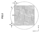
- Fig. 2 is a plan view showing a pattern of the conventional spatial light modulator 15.
- Square pixels a single side of which has a length of "a" ( ⁇ m) are arranged in a matrix.
- a pixel pitch of the spatial light modulator 15 is "a" ( ⁇ m).
- the reference numeral 6 indicates an incident beam which is incident on the spatial light modulator 15.
- the optical axis of the signal light represents a Z direction
- the directions of columns and rows of the pixels in a plane perpendicular to the signal light represent X and Y directions, respectively.
- the signal light interferes with the reference light to record inside the recording medium 5
- light intensity distributions of spatial frequency spectrum occur in the XY plane, which is in parallel with the Fourier plane, symmetrically with respect to the optical axis of the signal light.
- the hologram recording using a Fourier transform hologram has the advantages that hologram fits into spatially limited space, information is recorded in a distributed manner by use of Fourier transform, and the redundancy of recording can be increased.
- the distance (d1) between a zero-order Fourier spectrum and the first-order Fourier spectrum in the Fourier plane is expressed as follows, with the use of a spatial frequency (fsp) in a recording plane, the wavelength ( ⁇ ) of light, and the focal length (Fl) of the Fourier transform lens.
- d1 fsp • ⁇ • Fl
- the pixel pitch of the spatial light modulator 15 is 42 ⁇ m, the wavelength is 532nm, and the focal length is 165mm, the Fourier spectrum distance (d1) of the corresponding highest frequency component is 2.1mm, according to the foregoing equation.
- information to be recorded exists in a range of approximately ⁇ 2.1mm on the optical axis.
- two-dimensional data appearing in the spatial light modulator 15 is distributed over xy space (x, y ⁇ ⁇ 2d1) in a matrix with two rows and two columns, which is composed of the first-order diffracted light and zero-order light.
- a peak appears in a Fourier transformed image of the spatial light modulator 15, in accordance with the highest frequency component due to the pixel pitch. These peaks themselves do not bear any meaningful data. If these peaks occur in such a Fourier transformed image, the photorefractive effect of the recording medium becomes saturated in the above-mentioned peak position, so that there is a problem that nonlinear distortion tends to occur in a recorded image.
- an object to be achieved by the present invention includes one example of the foregoing problems.
- an object of the present invention is to provide a spatial light modulator with high performance which can record with high sensitivity and less signal distortion.
- a plurality of light modulation elements are arranged in one plane.
- the plurality of light modulation elements are arranged so that there are at least two periods of periodic structure corresponding to the arrangement of the light modulation elements in an arbitrary direction in the plane.
- a plurality of light modulation elements are arranged in a circular light modulation region.
- the plurality of light modulation elements are arranged so that there are at least two periods of periodic structure corresponding to the arrangement of the light modulation elements in an arbitrary direction in the light modulation region.
- the size of the light modulation element increases along the outer peripheral direction of the light modulation region.
- a spatial light modulator according to the present invention has a circular light modulation region.
- a light modulation element is disposed in each of areas which are obtained by radially and concentrically dividing the light modulation region.
- Fig. 4 is a block diagram showing the structure of a hologram recording and reproducing apparatus 10 which uses a spatial light modulator 40 according to a first embodiment of the present invention.
- a solid-state laser for emitting green light with a wavelength of 532nm is used as a light source of signal light 12A and recording reference light 12B.
- a laser light source 11 is driven by a laser driver 31.
- the laser driver 31 is controlled by a main controller (CPU) 30 connected to each circuit block of the hologram recording and reproducing apparatus 10 to carry out the control of the whole apparatus. More specifically, various control signals including a write timing signal and the like is supplied from the main controller 30 to the laser driver 31, and the laser driver 31 drives the laser light source 11 on the basis of the control signals.
- Laser light 12 emitted from the laser light source 11 is divided into the signal light 12A and the recording reference light 12B by a beam splitter 13.
- a beam expander 14 magnifies the beam diameter of the signal light 12A, and the signal light 12A is incident on the spatial light modulator (SLM) 40, which comprises a panel of a translucent TFT liquid crystal display (LCD), as collimated light.
- SLM spatial light modulator
- a plurality of light modulation elements are arranged in the spatial light modulator (SLM) 40, in such a manner that there are at least two periods of periodic structure which corresponds to the arrangement of the light modulation elements in an arbitrary direction in a plane.
- the light modulation elements are arranged so that there are at least two peak components of a Fourier frequency in a Fourier plane corresponding to the arrangement of the light modulation elements.
- the spatial light modulator (SLM) 40 has a circular light modulation region or area 6A which is approximately inscribed with the beam diameter 6 of the signal light.
- the light modulation region 6A is divided every predetermined angle ( ⁇ ) by radial partition lines passing through the center of the circle.
- the light modulation region 6A is also concentrically divided by partition lines the radiuses of which are R 1 , R 2 , ..., R n .
- pixel light modulation element
- each of the pixels A 1,1 , A 1,2 , ..., A 1,n is configured so as to have a different pitch in a radial direction. It is preferable that no pixel has the same pitch. If the pixels are configured so that the reciprocals of the pitches are the approximately same values, the distance between Fourier spectra can be evenly distributed. By configuring the spatial light modulator 40 in this manner, the distance between Fourier spectra each of which corresponds to each pixel differs in the Fourier plane, so that it is possible to prevent a peak from occurring in a specific position in a Fourier transformed image.
- pixels with high spatial frequencies i.e., small pixels are arranged in a central portion
- pixels with low spatial frequencies i.e., large pixels are arranged in a peripheral portion, in order to effectively obtain an amount of incident light on a lens.
- each pixel A 1,1 , A 1,2 , ..., A 1,n is determined in accordance with the power density of a signal light beam.
- the power density is high in the central portion of the beam, and decreases with approaching the peripheral portion of the beam.
- the size of each pixel is determined so that the power of light incident on each pixel becomes substantially equal.
- the size of each pixel may be determined so that a ratio of the power of light incident on each pixel is within a predetermined range.
- the spatial light modulator (SLM) 40 forms a bright and dark pattern on the basis of a data signal to be recorded.
- an encoder 25 receives the recording data signal which comprises a one-dimensional digital signal sequence, to convert the signal into a two-dimensional data array in accordance with the pixel array of the foregoing spatial light modulator (SLM) 40. Furthermore, the encoder 25 adds an error correction code to the two-dimensional data array, and generates a two-dimensional data signal (a unit page series data signal).
- the encoder 25 is provided with an SLM driver (not illustrated).
- the SLM driver generates a driving signal on the basis of the two-dimensional data signal, to drive the spatial light modulator (SLM) 40. Therefore, a two-dimensional pattern is formed in the spatial light modulator (SLM) 40 in accordance with the two-dimensional data signal.
- the spatial light modulator 40 When the signal light 12A passes through the spatial light modulator (SLM) 40, it is subjected to light modulation with the pattern.
- the spatial light modulator 40 has a modulation processing unit which corresponds to a unit page.
- the spatial light modulator 40 turns on or off the light of an applied coherent signal beam with a wavelength of 532nm pixel-by-pixel, in accordance with unit page series data from the encoder 25, in order to generate a modulated signal light beam.
- the spatial light modulator 40 passes the signal beam when a logical value of unit page series data, being an electric signal, is "1," and intercepts the signal beam when the logical value is "0.”
- electro-optic conversion is accomplished in accordance with the contents of each bit in unit page data, and hence the modulated signal light beam (signal beam) is generated as signal light of a unit page series.
- the signal light 12A including the recording data signal passes through a Fourier transform lens 16 which is disposed a focal length "f" away, and the pattern signal component is subjected to Fourier transform to be condensed into the recording medium 5.
- the recording reference light 12B intersects with an optical path of the signal light 12A inside the recording medium 5 and forms a light-interference pattern, to record the whole light-interference pattern as variations in a refractive index.
- the Fourier transform lens forms an image from diffracted light from the spatial light modulator, which is illuminated by coherent light and modulated with image data.
- the image interferes with the coherent reference light, and interference patterns are recorded in the recording medium in the vicinity of a focal point.
- a recording medium driver 33 moves the position of the recording medium 5 in parallel by a predetermined amount, and the second page is recorded in the same procedure. Recording is carried out by successive recording like this.
- the image is reproduced by carrying out inverse Fourier transform.
- a shutter 17 or the spatial light modulator (SLM) 40 interrupts the optical path of the signal light 12A, so that only the reference light 12B is incident in the recording medium 5.
- SLM spatial light modulator
- the present invention it is possible to reduce the intensity of the light peak occurring in the Fourier transformed image, which is caused by the periodic structure of the spatial light modulator.
- the intensity of the light peak occurring in the Fourier transformed image which is caused by the periodic structure of the spatial light modulator.
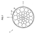
- Fig. 7 is a schematic plan view showing the structure of a spatial light modulator 41 according to a second embodiment of the present invention.
- the spatial light modulator 41 comprises a panel of a transmission-type TFT liquid crystal display (LCD).
- LCD liquid crystal display
- the spatial light modulator (SLM) 41 comprises a plurality of light modulation elements (pixels) 41A, each of which has the shape of a circle.
- the plurality of pixels 41A are arranged in the plane of the spatial light modulator 41, in such a manner as to satisfy any one of the following conditions.
- the pixels may be arranged so as to satisfy a plurality of the foregoing conditions.
- the pixels are arranged so as to satisfy all of the foregoing conditions (1) to (3).
- the size of each pixel is determined in accordance with the power density of a signal light beam. Namely, when the signal light beam density has the shape of Gaussian distribution, the power density is high in the central portion of the beam, and decreases with approaching the peripheral portion of the beam. Therefore, the size of each pixel may be determined so that a ratio of the power of light incident on each pixel is within a predetermined range.
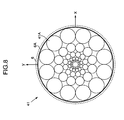
- Fig. 8 is a schematic plan view showing another embodiment of the spatial light modulator 41 according to the present invention.
- Each light modulation element (pixel) 41A has the shape of a circle, and the size of each pixel increases toward the outer peripheral direction of the light modulation region 6A.
- a spatial light modulator 42 may comprise rectangular pixels 42A.
- the pixels 42A are arranged so as to satisfy all of the foregoing conditions (1) to (3).
- every pixel does not need to be in the same shape. In other words, it is unnecessary that all pixels have the shape of a circle or a rectangle, and pixels in random shapes may be arranged.
Abstract
Description
- The present invention relates to a spatial light modulator and the like which are used in a hologram recording and reproducing apparatus and the like.
- A volume holographic recording system is known as a digital information recording system using the principle of hologram. The feature of this system is to record an information signal in a recording medium as variations in a refractive index. In the system, photorefractive material such as lithium niobate single crystal and the like is used for the recording medium.
- As one of hologram recording and reproducing methods, there is a method for recording and reproducing by use of Fourier transform.
- Fig. 1 shows an example of a conventional hologram recording and reproducing apparatus. In this drawing,
laser light 12 emitted from alaser light source 11 is divided into asignal light 12A and arecording reference light 12B by abeam splitter 13. The beam diameter of thesignal light 12A is magnified by abeam expander 14, and thesignal light 12A is applied to a spatial light modulator (SLM) 15 such as a panel of a translucent TFT liquid crystal display (LCD) and the like as collimated light. The spatial light modulator (SLM) 15 receives recording data converted by anencoder 25 as an electric signal, to form a bright and dark dot pattern on a plane. In passing through the spatial light modulator (SLM) 15, thesignal light 12A is modulated to include a data signal component. When thesignal light 12A including the signal component of the dot pattern passes through aFourier transform lens 16, which is disposed a focal length "f" away, the signal component of the dot pattern is subjected to Fourier transform, and is condensed into therecording medium 5. - On the other hand, the
recording reference light 12B divided by thebeam splitter 13 is led into the recording medium (volume holographic memory) 5 by amirror 18 and amirror 19. Therecording reference light 12B intersects with an optical path of thesignal light 12A inside therecording medium 5 and forms a light-interference pattern, to record the whole light-interference pattern as variations in a refractive index. - The Fourier transform lens, as described above, forms an image from diffracted light of image data, which is illuminated by coherent collimated light. The image is converted into distribution on a focal plane, that is, on a Fourier plane, and the distribution as a result of Fourier transform is allowed to interfere with the coherent reference light, in order to record interference fringes on the recording medium in the vicinity of a focal point. After completing the recording of a single data page (hereinafter, also simply referred to as a "page"), the
mirror 19 is rotated at a predetermined angle, and the position thereof is moved in parallel by a predetermined amount, in order to vary an incident angle of therecording reference light 12B with respect to therecording medium 5. Then, the second page is recorded in the same procedure. Angular multiplexing recording is carried out by successively performing the recording like this. - In reproducing operation, on the other hand, inverse Fourier transform is carried out to reproduce a dot pattern image. In reproducing data, as shown in Fig. 1, the optical path of the
signal light 12A is interrupted by, for example, the spatial light modulator (SLM) 15, and only thereference light 12B is applied to therecording medium 5. During reproduction, the position and angle of themirror 19 are varied and controlled with the use of the combination of the rotation and linear movement of themirror 19 so that the incident angle of the recording reference light becomes the same as that in recording a page to be reproduced. Reproduction light which reproduces the recorded light-interference pattern appears on the opposite side of therecording medium 5 irradiated with thereference light 12B. A dot pattern signal can be reproduced by leading the reproduction light into an inverseFourier transform lens 16A to carry out inverse Fourier transform. Then, the dot pattern signal is received by aphotodetector 20 such as a charge-coupled device CCD and the like in the position of a focal length, to reconvert the dot pattern signal into an electric digital data signal. Then, the digital data signal is sent to adecoder 26, so that original data is reproduced. - In the hologram recording with Fourier transform, the first-order diffracted light becomes the highest frequency component of the signal light, which is Fourier transformed by the
spatial light modulator 15 such as the LCD and the like, due to the repeats of pixels of thespatial light modulator 15. - Fig. 2 is a plan view showing a pattern of the conventional
spatial light modulator 15. Square pixels a single side of which has a length of "a" (µm) are arranged in a matrix. In other words, a pixel pitch of thespatial light modulator 15 is "a" (µm). Thereference numeral 6 indicates an incident beam which is incident on thespatial light modulator 15. - Referring to Fig. 3, the optical axis of the signal light represents a Z direction, and the directions of columns and rows of the pixels in a plane perpendicular to the signal light represent X and Y directions, respectively. When the signal light interferes with the reference light to record inside the
recording medium 5, light intensity distributions of spatial frequency spectrum occur in the XY plane, which is in parallel with the Fourier plane, symmetrically with respect to the optical axis of the signal light. - The hologram recording using a Fourier transform hologram has the advantages that hologram fits into spatially limited space, information is recorded in a distributed manner by use of Fourier transform, and the redundancy of recording can be increased. The distance (d1) between a zero-order Fourier spectrum and the first-order Fourier spectrum in the Fourier plane is expressed as follows, with the use of a spatial frequency (fsp) in a recording plane, the wavelength (λ) of light, and the focal length (Fl) of the Fourier transform lens.
- Since the pixel pitch of the
spatial light modulator 15 is 42µm, the wavelength is 532nm, and the focal length is 165mm, the Fourier spectrum distance (d1) of the corresponding highest frequency component is 2.1mm, according to the foregoing equation. Thus, information to be recorded exists in a range of approximately ±2.1mm on the optical axis. In other words, as shown in Fig. 3, two-dimensional data appearing in thespatial light modulator 15 is distributed over xy space (x, y ≤ ±2d1) in a matrix with two rows and two columns, which is composed of the first-order diffracted light and zero-order light. - Therefore, a peak appears in a Fourier transformed image of the
spatial light modulator 15, in accordance with the highest frequency component due to the pixel pitch. These peaks themselves do not bear any meaningful data. If these peaks occur in such a Fourier transformed image, the photorefractive effect of the recording medium becomes saturated in the above-mentioned peak position, so that there is a problem that nonlinear distortion tends to occur in a recorded image. - Also there is a method for offsetting the recording medium from the Fourier plane in order to secure a dynamic range during recording, but the method has the problems that time necessary for recording becomes long, an S/N ratio decreases, highly sensitive recording medium is needed, and the like.
- Considering the foregoing problems, an object to be achieved by the present invention includes one example of the foregoing problems. In other words, an object of the present invention is to provide a spatial light modulator with high performance which can record with high sensitivity and less signal distortion.
- In a spatial light modulator according to the present invention, a plurality of light modulation elements are arranged in one plane. The plurality of light modulation elements are arranged so that there are at least two periods of periodic structure corresponding to the arrangement of the light modulation elements in an arbitrary direction in the plane.
- In a spatial light modulator according to the present invention, a plurality of light modulation elements are arranged in a circular light modulation region. The plurality of light modulation elements are arranged so that there are at least two periods of periodic structure corresponding to the arrangement of the light modulation elements in an arbitrary direction in the light modulation region. The size of the light modulation element increases along the outer peripheral direction of the light modulation region.
- A spatial light modulator according to the present invention has a circular light modulation region. A light modulation element is disposed in each of areas which are obtained by radially and concentrically dividing the light modulation region.
-
- Fig. 1 is a diagram showing an example of a conventional hologram recording and reproducing apparatus;
- Fig. 2 is a plan view showing a pattern of a conventional spatial light modulator in which square pixels, a side of which has a length of "a", are arranged in a matrix;
- Fig. 3 is a diagram showing a light intensity of frequency spectrum, which occurs in an xy plane in parallel with a Fourier plane due to the interference between signal light and reference light;
- Fig. 4 is a block diagram showing the structure of a hologram recording and reproducing apparatus which uses a spatial light modulator according to a first embodiment of the present invention;
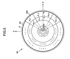
- Fig. 5 is a schematic plan view showing the shapes of light modulation elements in the spatial light modulator according to the first embodiment of the present invention;
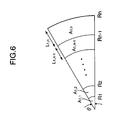
- Fig. 6 is a partly enlarged view of the spatial light modulator shown in Fig. 5;
- Fig. 7 is a schematic plan view showing the structure of a spatial light modulator according to a second embodiment of the present invention;
- Fig. 8 is a schematic plan view showing the structure of a spatial light modulator with circular light modulation elements according to another embodiment of the present invention; and
- Fig. 9 is a schematic plan view showing the structure of a spatial light modulator with rectangular light modulation elements according to further another embodiment of the present invention.
-
- Embodiments of the present invention will be described in detail with reference to the drawings. In the drawings described below, substantially identical parts are denoted by the same reference numerals.
- Fig. 4 is a block diagram showing the structure of a hologram recording and reproducing apparatus 10 which uses a spatial
light modulator 40 according to a first embodiment of the present invention. - In an
optical system 10A of the hologram recording and reproducing apparatus 10, for example, a solid-state laser for emitting green light with a wavelength of 532nm is used as a light source ofsignal light 12A andrecording reference light 12B. Alaser light source 11 is driven by alaser driver 31. Thelaser driver 31 is controlled by a main controller (CPU) 30 connected to each circuit block of the hologram recording and reproducing apparatus 10 to carry out the control of the whole apparatus. More specifically, various control signals including a write timing signal and the like is supplied from themain controller 30 to thelaser driver 31, and thelaser driver 31 drives thelaser light source 11 on the basis of the control signals. -
Laser light 12 emitted from thelaser light source 11 is divided into thesignal light 12A and therecording reference light 12B by abeam splitter 13. Abeam expander 14 magnifies the beam diameter of thesignal light 12A, and thesignal light 12A is incident on the spatial light modulator (SLM) 40, which comprises a panel of a translucent TFT liquid crystal display (LCD), as collimated light. - A plurality of light modulation elements are arranged in the spatial light modulator (SLM) 40, in such a manner that there are at least two periods of periodic structure which corresponds to the arrangement of the light modulation elements in an arbitrary direction in a plane. In other words, the light modulation elements are arranged so that there are at least two peak components of a Fourier frequency in a Fourier plane corresponding to the arrangement of the light modulation elements.
- In this embodiment, as shown in a plan view of Fig. 5, the spatial light modulator (SLM) 40 has a circular light modulation region or
area 6A which is approximately inscribed with thebeam diameter 6 of the signal light. Thelight modulation region 6A is divided every predetermined angle () by radial partition lines passing through the center of the circle. Thelight modulation region 6A is also concentrically divided by partition lines the radiuses of which are R1, R2, ..., Rn. Each divided area corresponds to a light modulation element (hereinafter, also referred to as pixel) 40A, and hence the spatiallight modulator 40 comprises pixels Ak,1, Ak,2, ..., Ak,n (k=1, 2, ..., m). Therefore, the spatiallight modulator 40 comprises nxm pixels. - Taking a case of k=1, for example, as shown in a partly enlarged view of Fig. 6, each of the pixels A1,1, A1,2, ..., A1,n is configured so as to have a different pitch in a radial direction. It is preferable that no pixel has the same pitch. If the pixels are configured so that the reciprocals of the pitches are the approximately same values, the distance between Fourier spectra can be evenly distributed. By configuring the spatial
light modulator 40 in this manner, the distance between Fourier spectra each of which corresponds to each pixel differs in the Fourier plane, so that it is possible to prevent a peak from occurring in a specific position in a Fourier transformed image. - Furthermore, in this embodiment, pixels with high spatial frequencies, i.e., small pixels are arranged in a central portion, and pixels with low spatial frequencies, i.e., large pixels are arranged in a peripheral portion, in order to effectively obtain an amount of incident light on a lens. In other words, the length L1,j (j=1, 2, ..., n) of each pixel A1,1, A1,2, ..., A1,n in a radial direction becomes long as the pixel approaches the peripheral portion (as j increases).
- Furthermore, the size of each pixel A1,1, A1,2, ..., A1,n is determined in accordance with the power density of a signal light beam. In other words, when the signal light beam has the shape of Gaussian distribution, the power density is high in the central portion of the beam, and decreases with approaching the peripheral portion of the beam. Thus, the size of each pixel is determined so that the power of light incident on each pixel becomes substantially equal. The size of each pixel may be determined so that a ratio of the power of light incident on each pixel is within a predetermined range.
- The spatial light modulator (SLM) 40 forms a bright and dark pattern on the basis of a data signal to be recorded. To be more specific, an
encoder 25 receives the recording data signal which comprises a one-dimensional digital signal sequence, to convert the signal into a two-dimensional data array in accordance with the pixel array of the foregoing spatial light modulator (SLM) 40. Furthermore, theencoder 25 adds an error correction code to the two-dimensional data array, and generates a two-dimensional data signal (a unit page series data signal). Theencoder 25 is provided with an SLM driver (not illustrated). The SLM driver generates a driving signal on the basis of the two-dimensional data signal, to drive the spatial light modulator (SLM) 40. Therefore, a two-dimensional pattern is formed in the spatial light modulator (SLM) 40 in accordance with the two-dimensional data signal. - When the
signal light 12A passes through the spatial light modulator (SLM) 40, it is subjected to light modulation with the pattern. In other words, the spatiallight modulator 40 has a modulation processing unit which corresponds to a unit page. The spatiallight modulator 40 turns on or off the light of an applied coherent signal beam with a wavelength of 532nm pixel-by-pixel, in accordance with unit page series data from theencoder 25, in order to generate a modulated signal light beam. To be more specific, the spatiallight modulator 40 passes the signal beam when a logical value of unit page series data, being an electric signal, is "1," and intercepts the signal beam when the logical value is "0." Thus, electro-optic conversion is accomplished in accordance with the contents of each bit in unit page data, and hence the modulated signal light beam (signal beam) is generated as signal light of a unit page series. - The
signal light 12A including the recording data signal passes through aFourier transform lens 16 which is disposed a focal length "f" away, and the pattern signal component is subjected to Fourier transform to be condensed into therecording medium 5. - The
recording reference light 12B divided through thebeam splitter 13, on the other hand, is led into a recording medium (volume holographic memory) 5 by amirror 18 and amirror 19. Therecording reference light 12B intersects with an optical path of thesignal light 12A inside therecording medium 5 and forms a light-interference pattern, to record the whole light-interference pattern as variations in a refractive index. - The Fourier transform lens, as described above, forms an image from diffracted light from the spatial light modulator, which is illuminated by coherent light and modulated with image data. The image interferes with the coherent reference light, and interference patterns are recorded in the recording medium in the vicinity of a focal point. Upon completing the recording of a single data page (hereinafter, also simply referred to as "page"), a
recording medium driver 33 moves the position of therecording medium 5 in parallel by a predetermined amount, and the second page is recorded in the same procedure. Recording is carried out by successive recording like this. - In reproducing, on the other hand, the image is reproduced by carrying out inverse Fourier transform. In the reproduction of data, for example as shown in Fig. 4, after the
recording medium driver 33 moves therecording medium 5 to a predetermined position, ashutter 17 or the spatial light modulator (SLM) 40 interrupts the optical path of thesignal light 12A, so that only thereference light 12B is incident in therecording medium 5. Thus, reproduction light is reproduced from the recorded light-interference pattern. A pattern signal is reproduced by leading the reproduction light into an inverseFourier transform lens 16A and carrying out inverse Fourier transform. Then, after the pattern signal received by aphotodetector 20 such as a charge-coupled device (CCD) and the like is reconverted into an electric digital data signal, the digital data signal is sent to thedecoder 26 in order to reproduce recorded data. - According to the present invention, it is possible to reduce the intensity of the light peak occurring in the Fourier transformed image, which is caused by the periodic structure of the spatial light modulator. Thus, it is possible to prevent the photorefractive effect of the recording medium from being saturated. Therefore, it is possible to provide a spatial light modulator with high performance, by which nonlinear distortion is hard to occur and hologram recording is carried out with high sensitivity.
- Fig. 7 is a schematic plan view showing the structure of a spatial
light modulator 41 according to a second embodiment of the present invention. The spatiallight modulator 41 comprises a panel of a transmission-type TFT liquid crystal display (LCD). - As shown in the plan view of Fig. 7, the spatial light modulator (SLM) 41 comprises a plurality of light modulation elements (pixels) 41A, each of which has the shape of a circle. The plurality of
pixels 41A are arranged in the plane of the spatiallight modulator 41, in such a manner as to satisfy any one of the following conditions. - (1) The
pixels 41A are arranged so that spatial frequencies by thepixels 41A in an arbitrary line in the plane of the spatiallight modulator 41 become plural, or - (2) The plurality of
pixels 41A have random sizes, or - (3) The pixel with a high spatial frequency, i.e., the small pixel is arranged in a central portion, and the pixel with a low spatial frequency, i.e., the large pixel is arranged in a peripheral portion.
-
- The pixels may be arranged so as to satisfy a plurality of the foregoing conditions. In this embodiment, the pixels are arranged so as to satisfy all of the foregoing conditions (1) to (3).
- It is preferable that the size of each pixel is determined in accordance with the power density of a signal light beam. Namely, when the signal light beam density has the shape of Gaussian distribution, the power density is high in the central portion of the beam, and decreases with approaching the peripheral portion of the beam. Therefore, the size of each pixel may be determined so that a ratio of the power of light incident on each pixel is within a predetermined range.
- Fig. 8 is a schematic plan view showing another embodiment of the spatial
light modulator 41 according to the present invention. Each light modulation element (pixel) 41A has the shape of a circle, and the size of each pixel increases toward the outer peripheral direction of thelight modulation region 6A. - Each pixel does not need to be in the shape of a circle. As shown in Fig. 9, a spatial
light modulator 42 may compriserectangular pixels 42A. In this embodiment, thepixels 42A are arranged so as to satisfy all of the foregoing conditions (1) to (3). - Furthermore, every pixel does not need to be in the same shape. In other words, it is unnecessary that all pixels have the shape of a circle or a rectangle, and pixels in random shapes may be arranged.
- According to such a structure, since light peak intensity occurring in the Fourier transformed image is reduced, it is possible to prevent the photorefractive effect of the recording medium from being saturated. Therefore, it is possible to provide a spatial light modulator with high performance, by which nonlinear distortion is hard to occur and hologram recording is carried out with high sensitivity.
Claims (6)
- A spatial light modulator, in which a plurality of light modulation elements are arranged in one plane, wherein:said plurality of light modulation elements are arranged such that there are at least two periods of periodic structure corresponding to an arrangement of the light modulation elements in an arbitrary direction in said plane.
- A spatial light modulator, in which a plurality of light modulation elements are arranged in a light modulation region of a circular shape, wherein:said plurality of light modulation elements are arranged such that there are at least two periods of periodic structure corresponding to an arrangement of the light modulation elements in an arbitrary direction in said light modulation region, and sizes of the light modulation elements increases along an outer peripheral direction of said light modulation region.
- The spatial light modulator according to claim 2, wherein said plurality of light modulation elements have an area ratio in accordance with a shape of Gaussian distribution, a peak point of said Gaussian distribution being in the center of said light modulation region.
- A spatial light modulator having a light modulation region of a circular shape, comprising:light modulation elements arranged in areas which are obtained by radially and concentrically dividing said light modulation region.
- The spatial light modulator according to claim 4, wherein said light modulation elements are arranged such that there are at least two periods of periodic structure corresponding to an arrangement of the light modulation elements in a radial direction of said light modulation region.
- The spatial light modulator according to claim 4, wherein said light modulation elements have an area ratio in accordance with a shape of Gaussian distribution, a peak point of said Gaussian distribution being in the center of said light modulation region.
Applications Claiming Priority (3)
| Application Number | Priority Date | Filing Date | Title |
|---|---|---|---|
| JP2002227535A JP3844460B2 (en) | 2002-08-05 | 2002-08-05 | Spatial light modulator |
| JP2002227535 | 2002-08-05 | ||
| PCT/JP2003/009299 WO2004013707A1 (en) | 2002-08-05 | 2003-07-23 | Spatial optical modulator |
Publications (2)
| Publication Number | Publication Date |
|---|---|
| EP1528442A1 true EP1528442A1 (en) | 2005-05-04 |
| EP1528442A4 EP1528442A4 (en) | 2008-04-02 |
Family
ID=31492215
Family Applications (1)
| Application Number | Title | Priority Date | Filing Date |
|---|---|---|---|
| EP03741552A Withdrawn EP1528442A4 (en) | 2002-08-05 | 2003-07-23 | Spatial optical modulator |
Country Status (6)
| Country | Link |
|---|---|
| US (1) | US7324255B2 (en) |
| EP (1) | EP1528442A4 (en) |
| JP (1) | JP3844460B2 (en) |
| CN (1) | CN100440077C (en) |
| AU (1) | AU2003281799A1 (en) |
| WO (1) | WO2004013707A1 (en) |
Cited By (1)
| Publication number | Priority date | Publication date | Assignee | Title |
|---|---|---|---|---|
| EP1703501A2 (en) * | 2005-03-14 | 2006-09-20 | THOMSON Licensing | Data page pixel shaping for holographic recording |
Families Citing this family (17)
| Publication number | Priority date | Publication date | Assignee | Title |
|---|---|---|---|---|
| US20030128324A1 (en) * | 2001-11-27 | 2003-07-10 | Woods Daniel D. | Pixel size enhancements |
| US20080247010A1 (en) * | 2005-03-16 | 2008-10-09 | Pioneer Corporation | Hologram Recording and Reproducing Apparatus and Hologram Recording Method |
| JP4617487B2 (en) * | 2005-03-18 | 2011-01-26 | 富士通株式会社 | Hologram recording device |
| JP2006259519A (en) * | 2005-03-18 | 2006-09-28 | Fujitsu Ltd | Hologram recording apparatus |
| JP2007240580A (en) * | 2006-03-06 | 2007-09-20 | Fujitsu Ltd | Hologram recording and reproducing apparatus |
| JP2007240581A (en) * | 2006-03-06 | 2007-09-20 | Fujitsu Ltd | Hologram recording device |
| JP2007257802A (en) * | 2006-03-24 | 2007-10-04 | Fujifilm Corp | Optical recording method, optical recording device, and optical recording medium |
| JP2008033021A (en) * | 2006-07-28 | 2008-02-14 | Fuji Xerox Co Ltd | Hologram recording method and hologram recording device |
| JP5192209B2 (en) * | 2006-10-06 | 2013-05-08 | 東京エレクトロン株式会社 | Plasma etching apparatus, plasma etching method, and computer-readable storage medium |
| JP2008275817A (en) * | 2007-04-27 | 2008-11-13 | Fujitsu Ltd | Hologram recording device |
| JP4830989B2 (en) * | 2007-06-27 | 2011-12-07 | 富士ゼロックス株式会社 | Hologram recording apparatus, hologram reproducing apparatus, hologram recording method, and hologram reproducing method |
| CN106933014B (en) * | 2010-09-07 | 2020-05-22 | 大日本印刷株式会社 | Optical module |
| CN103080630B (en) | 2010-09-07 | 2015-08-26 | 大日本印刷株式会社 | Employ the lighting device of coherent source |
| EP3064895B1 (en) | 2010-09-07 | 2020-04-15 | Dai Nippon Printing Co., Ltd. | Linear illumination device |
| EP3364651B1 (en) * | 2011-04-19 | 2020-03-04 | Dolby Laboratories Licensing Corporation | High luminance projection displays and associated methods |
| WO2014073611A1 (en) * | 2012-11-12 | 2014-05-15 | 浜松ホトニクス株式会社 | Phase modulation method and phase modulating device |
| CN111308877B (en) * | 2019-11-15 | 2022-03-25 | 北京理工大学 | Holographic optical element processing device |
Citations (3)
| Publication number | Priority date | Publication date | Assignee | Title |
|---|---|---|---|---|
| JPS63142962U (en) * | 1987-03-11 | 1988-09-20 | ||
| JPH02135425A (en) * | 1988-11-17 | 1990-05-24 | Matsushita Electric Ind Co Ltd | Active matrix array |
| EP0588509A2 (en) * | 1992-09-18 | 1994-03-23 | Fujitsu Limited | Stereoscopic display apparatus |
Family Cites Families (10)
| Publication number | Priority date | Publication date | Assignee | Title |
|---|---|---|---|---|
| JPS5028268B1 (en) * | 1970-12-25 | 1975-09-13 | ||
| US5107351A (en) * | 1990-02-16 | 1992-04-21 | Grumman Aerospace Corporation | Image enhanced optical correlator system |
| AUPM440494A0 (en) | 1994-03-11 | 1994-04-14 | Canon Information Systems Research Australia Pty Ltd | Intermingling subpixels in discrete level displays |
| JP2000098862A (en) | 1998-09-25 | 2000-04-07 | Fuji Xerox Co Ltd | Optical recording method and optical recorder |
| JP2000228284A (en) * | 1998-12-01 | 2000-08-15 | Sanyo Electric Co Ltd | Color el display device |
| JP3833842B2 (en) * | 1999-03-30 | 2006-10-18 | パイオニア株式会社 | Volume holographic memory and optical information recording / reproducing apparatus thereof |
| JP4045390B2 (en) * | 1999-03-30 | 2008-02-13 | 富士ゼロックス株式会社 | Optical recording method, optical recording apparatus, and optical reproducing method |
| KR100740481B1 (en) * | 1999-09-02 | 2007-07-19 | 아사히 가라스 가부시키가이샤 | Optical head |
| JP2002297008A (en) * | 2001-03-30 | 2002-10-09 | Pioneer Electronic Corp | Hologram recording medium, method for hologram recording and reproducing, and hologram recording and reproducing device |
| KR100397702B1 (en) * | 2001-08-29 | 2003-09-13 | 주식회사 대우일렉트로닉스 | Holographic digital data storage apparatus and data input/output method thereof |
-
2002
- 2002-08-05 JP JP2002227535A patent/JP3844460B2/en not_active Expired - Fee Related
-
2003
- 2003-07-23 CN CNB038188759A patent/CN100440077C/en not_active Expired - Fee Related
- 2003-07-23 WO PCT/JP2003/009299 patent/WO2004013707A1/en active Application Filing
- 2003-07-23 US US10/521,312 patent/US7324255B2/en not_active Expired - Fee Related
- 2003-07-23 AU AU2003281799A patent/AU2003281799A1/en not_active Abandoned
- 2003-07-23 EP EP03741552A patent/EP1528442A4/en not_active Withdrawn
Patent Citations (3)
| Publication number | Priority date | Publication date | Assignee | Title |
|---|---|---|---|---|
| JPS63142962U (en) * | 1987-03-11 | 1988-09-20 | ||
| JPH02135425A (en) * | 1988-11-17 | 1990-05-24 | Matsushita Electric Ind Co Ltd | Active matrix array |
| EP0588509A2 (en) * | 1992-09-18 | 1994-03-23 | Fujitsu Limited | Stereoscopic display apparatus |
Non-Patent Citations (1)
| Title |
|---|
| See also references of WO2004013707A1 * |
Cited By (2)
| Publication number | Priority date | Publication date | Assignee | Title |
|---|---|---|---|---|
| EP1703501A2 (en) * | 2005-03-14 | 2006-09-20 | THOMSON Licensing | Data page pixel shaping for holographic recording |
| EP1703501A3 (en) * | 2005-03-14 | 2009-12-09 | THOMSON Licensing | Data page pixel shaping for holographic recording |
Also Published As
| Publication number | Publication date |
|---|---|
| JP3844460B2 (en) | 2006-11-15 |
| CN1675597A (en) | 2005-09-28 |
| CN100440077C (en) | 2008-12-03 |
| AU2003281799A1 (en) | 2004-02-23 |
| EP1528442A4 (en) | 2008-04-02 |
| US20050275919A1 (en) | 2005-12-15 |
| US7324255B2 (en) | 2008-01-29 |
| WO2004013707A1 (en) | 2004-02-12 |
| JP2004069920A (en) | 2004-03-04 |
Similar Documents
| Publication | Publication Date | Title |
|---|---|---|
| US7324255B2 (en) | Spatial optical modulator | |
| KR101075351B1 (en) | Hologram recording device | |
| JP4790701B2 (en) | Holographic optical information recording / reproducing apparatus and holographic optical information recording / reproducing method | |
| US7535608B2 (en) | Hologram recording method and hologram recording apparatus | |
| KR100611420B1 (en) | Spatial light modulator and holographic recording/reproducing apparatus | |
| JPH11282331A (en) | Regenerating device for volume holographic memory light information record | |
| US7200097B2 (en) | Parallel recording and reading of diffractive memory using multiple object beams | |
| EP1507177A1 (en) | Multiplex recording type hologram recording device, method, hologram reproduction device, and method | |
| US20050231775A1 (en) | Hologram recording/reproducing method and hologram recording/reproducing device | |
| EP1550922B1 (en) | Hologram recording device | |
| US20030043150A1 (en) | Method and apparatus for modifying page data | |
| US6301028B1 (en) | Holographic memory and optical information recording and reproducing apparatus using the same | |
| US20060176799A1 (en) | Optical information recording method and optical information recording and reproducing apparatus utilizing holography | |
| US7916369B2 (en) | Holographic recording and reproducing apparatus | |
| WO2005066724A1 (en) | Holographic multiple recording method, holographic recording device using the same, and holographic recording medium | |
| US20060164705A1 (en) | Hologram system | |
| JP2801257B2 (en) | Light beam scanning device | |
| JP2005135479A (en) | Hologram recording/reproducing device, hologram recording/reproducing method, phase modulation pattern display method, and phase modulation pattern creation method | |
| JP2000284672A (en) | Method and device for optical recording | |
| JP2005003828A (en) | Hologram recording apparatus and hologram recording method | |
| JP4975007B2 (en) | Hologram reproduction wavefront control method and apparatus | |
| KR100718436B1 (en) | Writing device on the holographic digital data storage system | |
| JP2005003829A (en) | Diffraction controller, hologram recording device, and method for hologram recording | |
| JP2005121855A (en) | Hologram recording and reproducing apparatus, hologram recording and reproducing method and phase modulation method for light beam | |
| KR20000002747A (en) | Volume holographic digital storage system |
Legal Events
| Date | Code | Title | Description |
|---|---|---|---|
| PUAI | Public reference made under article 153(3) epc to a published international application that has entered the european phase |
Free format text: ORIGINAL CODE: 0009012 |
|
| 17P | Request for examination filed |
Effective date: 20050224 |
|
| AK | Designated contracting states |
Kind code of ref document: A1 Designated state(s): AT BE BG CH CY CZ DE DK EE ES FI FR GB GR HU IE IT LI LU MC NL PT RO SE SI SK TR |
|
| AX | Request for extension of the european patent |
Extension state: AL LT LV MK |
|
| DAX | Request for extension of the european patent (deleted) | ||
| RBV | Designated contracting states (corrected) |
Designated state(s): DE FR GB |
|
| A4 | Supplementary search report drawn up and despatched |
Effective date: 20080228 |
|
| 17Q | First examination report despatched |
Effective date: 20080606 |
|
| RAP1 | Party data changed (applicant data changed or rights of an application transferred) |
Owner name: PIONEER CORPORATION |
|
| STAA | Information on the status of an ep patent application or granted ep patent |
Free format text: STATUS: THE APPLICATION IS DEEMED TO BE WITHDRAWN |
|
| 18D | Application deemed to be withdrawn |
Effective date: 20130201 |